High Valley 2500 User manual

MODEL 2500 C E W H
High Valley Stoves by Stoll
185 Highway 201 │Abbeville, SC 29620
M 2500 C I L M 2500 F I
Safety Noce:
If this wood heater is not properly installed, a house fire may result.
For your safety, please carefully read and follow the installaon direcons. Contact the local Building Inspector,
Fire Official, or other Authority Having Jurisdicon (AHJ) about code requirements, restricons, and installaon
inspecon in your area. The AHJ can advise you if you are required to obtain a permit before installaon.
Failure to follow these instrucƟons can result in property damage, bodily injury, or even death.
Owner’s Manual
Safety, Installaon, Operaon, & Maintenance Guidelines
INSTALLER: Leave this manual with the individual (s) responsible for operang this wood heater.
OPERATOR: The Owner’s Manual contains important safety, operang, and maintenance informaon.
Please read and understand the enre Owner’s Manual before installing or operang this wood heater.
If you have quesons please contact your High Valley Dealer for assistance.
DO NOT DISPOSE OF THIS MANUAL
SAVE THIS OWNER’S MANUAL FOR FUTURE REFERENCE

2
H V S S
185 Highway 201 │Abbeville, SC 29620
www.highvalleystoves.com
U.S. ENVIRONMENTAL PROTECTION AGENCY
Cerfied to comply with 2015 parculate emission standards.
Not approved for sale aer May 15, 2020.
Under specific test condions this catalyc equipped wood heater has been shown to deliver heat at rates ranging from 7,700
to 40,929 Btu/hr. Emissions were determined to be 3.1 g/hr. The default EPA efficiency rang for catalyc equipped heaters
was 72% per the Federal Register, CFR - Title 40 - Part 60 - Subpart AAA, that was current at the me of tesng. Results of
CO (carbon monoxide) tesng were not required nor recorded at that me. EPA validated CO and efficiency values will be
published in future revisions of this manual, and on the High Valley website, as they become available.
This catalyc equipped wood heater has a manufacturer-set minimum low burn rate that must not be altered. This wood
heater contains a catalyc combustor, which needs periodic inspecon and replacement for proper operaon. It is against
federal regulaons to operate this wood heater in a manner inconsistent with operang instrucons in this manual, or if the
catalyc element is deacvated or removed.
This catalyc equipped wood heater needs periodic inspecon and repair for proper operaon. Consult the maintenance
secon of this owner’s manual for further informaon.
This catalyc wood heater is designed to burn natural wood only. Higher efficiencies and lower emissions generally result
when burning air dried seasoned hardwoods, as compared to sowoods or to green or freshly cut hardwoods.
DO NOT BURN:
• Garbage;
• Lawn clippings or yard waste;
• Materials containing rubber, including res;
• Materials containing plasc;
• Waste petroleum products, paints or paint thinners, or asphalt products;
• Materials containing asbestos;
• Construcon or demolion debris;
• Railroad es or pressure-treated wood;
• Manure or animal remains;
• Salt water driwood or other previously salt water saturated materials;
• Unseasoned wood; or
• Paper products, cardboard, plywood, or parcleboard. The prohibion against burning these ma-
terials does not prohibit the use of fire starters made from paper, cardboard, saw dust, wax and
similar substances for the purpose of starng a fire in an affected wood heater.
Burning these materials may result in release of toxic fumes or render the heater ineffecve and cause smoke.
Smoke Detectors should be Installed on every floor of your home; in the living areas and especially near bedrooms. Many ju-
risdicons now require hard wired Smoke Detectors and/or Carbon Monoxide (CO) Detectors be installed in specific locaons
in single family homes. If you are not subject to such a requirement then, at a minimum, baery operated detectors should
be installed. Test them regularly and install new baeries every six months. A smoke detector located in the same room as
a wood heater should be installed as far away from the heater as possible to prevent accidental acvaon when lighng or
refueling the fire. Smoke and CO detectors should be installed per the manufacturer’s instrucons and code requirements.
* New EPA regulaons require that the efficiency of a wood heater be determined by test under laboratory condions and expressed as a
percentage using the HHV (Higher Heang Value) and/or LHV (Lower Heang Value) of cord wood to provide consumers a benchmark to
use when comparing various models of wood heaters. Under the EPA Regulaons all Wood Heaters will be retested by the year 2020 using
the CSA B415.1-10 standard which will use weighted average of efficiencies achieved at different burn rates and will determine a CO value
as part of the tesng. To learn more, please visit www.highvalleystoves.com.
MODEL 2500 C E W H
Safety Tested by:
CONAM Inspection, Inc. AGTL | Natick, Massachusetts
Tested March 1988 to ANSI / UL 1482 Specifications
Emissions & Efficiency Tested by:
APEX Environmental Services, Inc. | Apex, NC 27502
Report 05.10.1993 | Tested to July 1990 Particulate Emission Standards
C

3
This manual describes the installaon, operaon, and maintenance of High Valley Stoves Model 2500 catalyc
equipped wood heater. This heater is cerfied to comply with the U.S. Environmental Protecon Agency’s crib
wood emission limits for wood heaters sold aer May 15, 2015.
Throughout this manual you will find important safety noces and informaon may be repeated a number of
mes. The repeon is intenonal in an effort to reinforce safety instrucons and to place them in context.
U.S. EPA E S T I P 2
G S I S P Page 4
I P P 5
C P P 6
C R G P 7
C C T D P 8
M 2500 F S C P 9
P-I A P 10
F W H I P 11
F W H C C P 12
M 2500 M F I P 13
F I D S I P 14
P-O A P 15
M 2500 F C P 15
O G P 16 17
T I P 18
C I T I P 19
C C R C P 20
C C D, R W P 21
L D M F P P 22
C B M P P 23
A A B W C P 24
A B H V W P 25
A C F W P P 25
W C P 26
O R S P 27
T C

4
Thank you for choosing a wood heater from High Valley Stoves. Safe and efficient operaon of your wood heater depends
greatly on proper installaon as outlined in this owner’s manual. If this wood heater is not properly installed, a house fire may
result. To reduce the risk of fire follow all instrucons, cauons, and safety noces contained herein. Installaon must also
meet all State and Local Code requirements and/or restricons. Check with your local Building Official, Fire Official, or other
Authority Having Jurisdicon (AHJ) regarding the need to obtain a permit prior to installing a wood heater; and whether an
inspecon of the installaon is required upon compleon. Understand that code requirements and follow-up inspecon are
not put in place to make the installaon process more difficult. Rather they are designed to help ensure your safety. Don’t
take shortcuts, use or allow makeshimethods, or other compromises in the installaon. Safety is paramount and the key
to enjoying your new wood heater. Installaon by an experienced professional installer who has the specialized knowledge,
tools, and equipment to complete the installaon safely is strongly recommended. Look for an installer who is cerfied by the
The Naonal Fireplace Instute (NFI) as a Woodstove Specialist or Master Hearth Professional (MHP) to have demonstrated
their mastery of the knowledge required in all phases of safe woodstove installaon, and of best current industry pracces.
Be sure to contact your insurance company to inquire whether they have addional requirements.
BURN SOLID WOOD FUEL ONLY. This wood heat-
er is designed and approved for the burning of cord
wood fuel only. Burning any type of fuel other than
cord wood in this wood heater is against all safety test-
ing and will void all warranes.
DO NOT USE CHEMICALS OR FLUIDS TO START
THE FIRE. Never use gasoline, gasoline-type lantern
fuel, kerosene, charcoal lighter fluid, or similar liquids
to start or “freshen up” a fire in this wood heater. Keep
all such liquids well away from the heater at all mes.
Storing these or other flammable liquids near a wood
heater could cause a fire.
DO NOT BURN GARBAGE OR FLAMMABLE FLU
IDS SUCH AS GASOLINE, NAPHTHA OR ENGINE
OIL. Cord wood is the only fuel approved for use in
this wood heater.
DO NOT CONNECT THIS UNIT TO A CHIMNEY
FLUE SERVICING ANOTHER APPLIANCE.
DO NOT CONNECT A WOOD HEATER TO, OR
USE IN CONJUNCTION WITH, ANY AIR DISTRI
BUTION DUCTWORK UNLESS SPECIFICALLY
APPROVED FOR SUCH INSTALLATIONS.
DO NOT OPERATE IN AN EXTREME MANNER AS
TO OVERFIRE THE WOOD HEATER. If any part
of the wood heater, the chimney, or the chimney con-
nector glows, you are over-firing. If over-firing occurs,
close all combuson air controls immediately. Over-
firing and/or aempts to achieve heat output rates
that exceed heater design specificaons can result in
permanent damage to the heater, and to the catalyc
combustor, and may cause a fire.
HOT WHILE IN OPERATION. KEEP CHILDREN,
CLOTHING, AND FURNITURE WELL AWAY.
CONTACT MAY CAUSE SKIN BURNS. Observe all
minimum clearances as listed in this manual. Maintain
a 36” area around the wood heater to be kept free of
combusble materials including furniture and window
treatments. DO NOT allow unaended children in the
area of an operang wood heater.
BURN DIRECTLY ON FIRE BRICKS. Do not use
grates, andirons, or other methods to support fuel.
FUEL STORAGE. Store bulk cord wood covered in a
well venlated area to ensure that the wood fuel is as
dry as possible. Do not store wood fuel within wood
heater minimum clearances or within the space need-
ed for loading the heater or for ash removal.
ASH DISPOSAL. Ashes should be placed in a steel
container with a ght-fing lid and moved outdoors
immediately. The closed container of ashes should be
placed on a non-combusble floor or on the ground,
well away from all combusble materials, pending final
disposal. If the ashes are disposed of by burial in soil or
otherwise locally dispersed, they should be retained in
the closed container unl all cinders have thoroughly
cooled. Other waste shall not be placed in this con-
tainer.
CREOSOTE FORMATION & REMOVAL. Inspect
chimney connector and chimney twice monthly, and
clean if necessary. Creosote accumulaon in the con-
nector pipe, chimney, or flue lining can create an ex-
tremely hot fire if ignited.
S P
G S I

5
Your new High Valley wood heater has been designed to give you years of clean, efficient service. Take me to consider
carefully where your new wood heater will be installed in your home. If you are planning to use an exisng chimney and/
or hearth, many of the decisions have been made for you. Consult with your High Valley dealer before comming to a final
locaon and take full advantage of their experience. Consider how you plan to use your wood heater, your expectaons, and
the physical layout of your home. Once the wood heater has been installed it would require significant effort and expense
to change its locaon. Perhaps, aer considering all factors, you may come to the conclusion that the locaon of an exisng
chimney may not be the best place for your new wood heater. Evaluate all of your opons fully before making a final decision.
L: The wood heater should be located in a place where it will be convenient to fuel and maintain the fire, but well
away from human traffic flow, and clear of hallways and doors. It must be possible to maintain the minimum clearances to
combusbles which were determined by safety tesng. See Page 9. Ensure that furniture, window treatments (draperies,
curtains, etc.) wood materials including wood fuel, and any other combusble materials will be no closer than 36" to the wood
heater. If children reside in the home, or visit regularly, consider how the area immediately around the heater can be closed
offto keep the children safely away from hot surfaces. Consult your High Valley dealer for advice on safety gates and other
safety products.
H C:Ideally the wood heater will be centrally located in the area that you wish to heat. A
wood heater is an excellent area heater or space heater. Properly sized and operated it will heat the area where it is located
and heated air will naturally move throughout the home. Keep in mind that a wood heater does not have the advantage of
a distribuon system to deliver the heat around your home like a central heang boiler or furnace. Don't expect the type of
even heat distribuon that a central heang system can deliver. If your goal is to heat a family room, an addion, or a poron
of the main house, the wood heater should be sized and operated to create a warm, comfortable space with the surplus heat
allowed to travel around the home on natural convecon (air) currents. A large wood heater with the capacity to heat a home
will typically overheat the area where it is located unless the home is constructed with an open floor plan. If heang a typical
paroned home with wood as a primary heat source is truly the goal, then it would be wise to consider installing a number
of smaller sized wood heaters throughout the space to be heated rather than a single large wood heater. The number would
depend on the size and layout of the home. Installing your wood heater in an uninsulated basement is not recommended.
Much of the heat produced will be lost to the uninsulated walls of the basement. Never cut holes or vents in a ceiling/floor in
an aempt to get warm air to rise to the rooms above. You will be compromising a firebreak in your home and could, should
a fire ensue, jeopardize your homeowner's insurance coverage. Contact your local Building Official, Fire Official, or other Au-
thority Having Jurisdicon for guidance.
C L:Once the best physical locaon for your wood heater from a heang perspecve is agreed upon,
the feasibility of providing a safe and effecve chimney in that locaon must be considered. If the chimney is to run up
through the ceiling and/or the roof then the space above must be clear. The layout and locaon of floor joists and/or roof
raers must be ascertained. Most factory-built chimney components are designed to fit into standard construcon without
the need for cung and boxing frame members. A factory-built chimney can also exit through the sidewall of the house and
up the side of the home. Another alternave would be to construct a new masonry chimney specifically for the wood heater.
In any case, the wood heater must not be vented into a chimney flue serving any other appliance. Once again, it is strongly
recommended that the chimney installaon be performed by a cerfied professional installer who is thoroughly familiar with
the requirements of modern wood heaters.
Your High Valley Model 2500 is approved for installaon into either a masonry chimney or a Type HT factory-built chimney
listed to UL-103-HT or ULC-S629 standards. A masonry chimney is a permanent installaon requiring a load bearing foong
to support the mass of the chimney. Factory-built chimneys offer flexible installaon opons and use proprietary support sys-
tems for through-the-roof or sidewall installaon. A properly constructed chimney that provides adequate drais essenal
for the safe and efficient operaon of your wood heater. More specific informaon about draand various chimney instal-
laons and material will follow, but lets begin at the beginning. Look back to a me when fireplaces, woodstoves, and later,
solid fuel central heang were relied on as the only source of heat in cold weather. Proper chimney construcon and locaon
could spell the difference between keeping warm in the winter and not. Those chimneys had to work. Life revolved around
the fireplace and, later, the cook stove and parlor stove. The chimney was typically built in the center of the home where it
helped warm the home and it, in turn, was kept warm by the home. The central locaon ensured that the chimney would exit
near the peak of the roof and therefore be as tall as possible. Our ancestors knew from experience that a tall, warm chimney
would drabeer and was less likely to be affected by wind and weather. The same principals apply today.
I P

6
Chimneys that were constructed in homes built before the advent of oil and gas-fired central heang systems were invariably
constructed within the walls of the home, typically centrally located, and exited the roof at or near the ridge. The principals
that applied then apply today. A chimney is best located within the envelope of the home to keep it warm, and it should be
installed as close to the peak of the roof as possible. If you have a modern fireplace that was constructed with the chimney
outside the home, exposed to the cold, and with a relavely short chimney, it may not be your best choice for use with a
modern, efficient wood heater. As central heang became prevalent, fireplaces and their chimneys were moved outside the
walls of the home to conserve floor space. If they didn't drawell it was not considered a major problem because the central
heang system kept the home warm.
D:The Environmental Protecon Agency defines drathis way: ‘‘Drais the force which moves air from the appliance
up through the chimney." Simply stated, heated air (wood heater exhaust or any heated gas for that maer) becomes more
buoyant and tends to rise. The hoer the gasses contained in a chimney flue are, compared to the temperature of the air
outside, the greater the drashould be. There are many variables and the scienfic explanaon can become complicated.
(There are books and scienfic papers wrien for those who would like to know more.) Suffice to say that you need it. With-
out adequate drayour wood heater cannot burn efficiently nor vent smoke properly. The draof the chimney provides the
sucon that pulls air into the wood heater to support combuson. A wood heater provided with adequate dracannot leak
smoke, as air is being drawn into the heater, connector pipe, and chimney. If a wood heater is leaking smoke or spills a lot of
smoke during refueling, inadequate drais most likely the culprit.
A complete explanaon of all of the elements that may affect draare beyond the scope of this manual but, briefly, some
factors that contribute to a properly draing chimney are these:
• F S:It is recommended that the flue size of the chimney be the same size as the flue outlet on the heater. Theo-
recally a larger chimney flue should have a greater flow capacity than a smaller flue. In pracce however, the heated
flue gases are diluted by the extra air in the larger flue and cool faster. Drais decreased therefore and, if cooled too
much, creosote may be deposited in the flue. The Model 2500 has an eight inch (8") flue collar and 8" factory-built HT
chimney is the preferred opon and is readily available. An exisng masonry chimney can be more challenging, de-
pending on the flue size. If the exisng masonry chimney has a single eight inch (8") square masonry flue le, it is only
slightly larger than the 8" flue of the Model 2500, and can be an acceptable opon, assuming that the masonry chimney
provides adequate dra. (The cross seconal area of an 8" round flue is 50¼ sq. in. {Area = πr2 or A = π42 or A = 3.14
X 16) where Pi = 3.1416} The cross seconal area of an 8" square masonry flue le is @ 64 sq. in.) However, masonry
chimneys commonly have 8" x 12" (@96 sq. in.) or even 12" x 12" (@144 sq. in.) flue les, which would be two (2X) to
three mes (3X) larger than the Model 2500 flue outlet, and may drapoorly. In addion, masonry construcon tends
to cool more quickly with cold outside temperatures. If a new masonry chimney is being constructed, ask the mason to
source 8" round flue les. They are available and can be insulated with vermiculite or other approved chimney insula-
on materials. The performance of an exisng masonry chimney may be improved significantly with the installaon of
an insulated chimney liner that is the same size as the flue outlet of the wood heater.
• I:A chimney flue that is kept warm is more likely to drawell than a cold chimney. Keeping the chimney
within the walls of the home is the best soluon if space allows. If the chimney must be constructed outside the home,
then insulang the chimney is strongly recommended. Factory-built HT chimneys are packed with insulang mate-
rial and can be further protected by installing them inside an insulated chimney chase (enclosure) outside the home.
Masonry chimneys may require an insulated flue liner to provide adequate drain all seasons. Consider that when it
is cold (20 degrees for example) outside the home, the air inside the flue of an outdoor chimney will be essenally the
same temperature. When lighng the fire it will be necessary to provide enough heat to overcome that column of cold
air acng like a plug in the chimney flue. Even aer the wood heater has been ignited and is burning, a cold chimney
can sll have a negave effect on dra. Hot flue gasses cool more quickly in a chimney exposed to the elements; per-
haps to the point were the drabecomes inadequate to maintain an efficient fire.
• H:A tall chimney is more likely to drawell than a short chimney. The taller column of heated gas creates a
greater temperature and pressure differenal with the outside atmosphere and beer drais the result. As above, the
flue size and insulaon also play significant roles in the process. A minimum chimney height of @ ten feet (10') and
a maximum height of @ thirty feet (30'), measured from the top of the wood heater, is recommended. Locang the
chimney where it will project above the ridge of the roof, rather than near the eaves of the home, will net the tallest
chimney height praccal for your home. External elements like tall trees, hills, tall buildings, and the like can affect dra
when the wind is blowing from a parcular direcon. Locang a short chimney at the eaves of the home may result in
draproblems when the wind blows across your own roof ridge. Height alone is not the only factor to consider when
specifying a chimney but, in general, taller is beer.
C P

7
Your High Valley Model 2500 must be connected to either a factory-built Type HT chimney or to a masonry chimney with a flue
liner of a construcon that meets all current code requirements. If the wood heater is to be connected to an exisng chimney,
have the chimney inspected prior to installing the wood heater by an NFI cerfied hearth installer, a CSIA chimney sweep, or
a qualified mason in the case of a masonry chimney. The chimney must prove to be sound and serviceable and to meet all
applicable codes. An exisng factory-built chimney must be Type HT, listed to UL-103-HT or ULC-S629 standards. An exist-
ing masonry chimney must have a clay le liner or approved stainless steel insulated liner. The wall thimble or pass-through
construcon should be inspected to ensure it conforms to current NFPA 211 guidelines. The flue size must not be less than
the flue collar or greater than three mes (3X) the cross-secon of the flue collar. NOTE: An oversize masonry chimney may
not prove to provide adequate draand may require the installaon of an insulated liner approved to UL 1777 to funcon
sasfactorily.
If a new chimney is to be constructed to vent the wood heater we strongly advise that the chimney be professionally installed.
Factory-built chimney must be Type HT-2100°F tested to the UL 103 standard and/or ULC S629 standard. An eight inch (8") di-
ameter factory-built chimney is preferred. All components of the factory-built chimney must be from the same manufacturer
and be of the same type to ensure proper connection of components. All chimney components needed for the installation
including but not limited to wall pass-throughs, tees and tee supports, ceiling supports, insulation shields, fire stops, roof
support packages, roof flashings, chimney caps, etc. must be installed exactly to the manufacturer's instructions. Installation
specification and clearances may vary from manufacturer to manufacturer and must be carefully adhered to according to the
individual manufacturer's instructions.
If a new masonry chimney is to be constructed, the use of a professional masonry contractor is strongly recommended.
Specialized knowledge is needed to ensure proper construction and support for a masonry chimney. The chimney must be
constructed in accordance with the latest edition of NFPA standard 211 and must conform to all applicable state and local
codes. Wall thimble construction and clearances to combustibles must meet NFPA 211 guidelines. A permit and inspection
may be required by the local Building Official, Fire Official, or other Authority Having Jurisdiction. An eight inch (8") round or
8" x 8" square flue tile is required. The flue tiles must be mortared together with the approved material and provided with an
air space as required by NFPA 211 and applicable codes. It is recommended that the masonry flue tiles be well insulated with
a material approved for the purpose.
The following informaon about chimney construcon and requirements is intended for reference only. The use of a profes-
sional installer is strongly recommended. Specific installaon instrucons and/or requirements must conform to the chimney
manufacturer's instrucons and/or applicable building codes. Seek the advice of your High Valley Dealer and/or the local
Authority Having Jurisdicon as to local code, perming, and inspecon requirements.
C H
• The top of the chimney must be at least two feet ( 2' or 0.6m) taller than the highest point of the roof or any part of the
roof or other structure within ten feet (10' or 3m) measured horizontally from the chimney terminaon.
• The chimney must be at least three feet (3' or 0.9m) taller than the high side of the roof penetraon.
C R
C G

8
A R:
• Insulaon material used as part of wall pass-through system shall be of noncombusble material and shall have a thermal
conducvity of 1.0 Btu-in./hr-- °F (4.88 kg-cal/hr-m - °C) or less.
• All clearances and thicknesses are minimums; larger clearances and thicknesses shall be permied.
• Any material used to close up an opening for the connector shall be of noncombusble material.
• A connector to a masonry chimney, except for System B, shall extend in one connuous piece through the wall pass-
through system and the chimney wall to the inner face of the flue liner, but not beyond.
• Minimum 3.5 inch (90mm) thick brick masonry wall framed into com-
busble wall with a minimum of 12 inch (305mm) brick separaon from
clay liner to combusbles. Fireclay liner (ASTM C 315, Standard Specifi-
caon for Clay Fire Linings, or equivalent), minimum ⁵⁄₈inch (16mm) wall
thickness, shall run from outer surface of brick wall to, but not beyond,
the inner surface of chimney flue liner and shall be firmly cemented in
place.
• Solid-insulated, listed factory-built chimney length of the same inside
diameter as the chimney connector and having 1 inch (25.4mm) or more
of insulaon with a minimum 9 inch (229mm) air space between the
outer wall of the chimney length and combusbles. The inner end of the
chimney length shall be flush with the inside of the masonry chimney
flue and shall be sealed to the flue and to the brick masonry penetraon
with non-water-soluble refractory cement. Supports shall be securely
fastened to wall surfaces on all sides. Fasteners between supports and
the chimney length shall not penetrate the chimney liner.
• Sheet steel chimney connector, minimum 24 gauge [0.024 inch (0.61
mm)] in thickness, with a venlated thimble, minimum 24 gauge [0.024
inch (0.61mm)] in thickness, having two 1 inch (25.4mm) air channels,
separated from combusbles by a minimum of 6 inches (152mm) of
glass fiber insulaon. Opening shall be covered, and thimble supported
with a sheet steel support, minimum 24 gauge [0.024 inch (0.61mm)]
in thickness. Supports shall be securely fastened to wall surfaces on all
sides and shall be sized to fit and hold chimney secon. Fasteners used
to secure chimney secon shall not penetrate chimney flue liner.
• Solid-insulated, listed factory-built chimney length with an inside diam-
eter 2 inches (51mm) larger than the chimney connector and having 1
inch (25.4mm) or more of insulaon, serving as a pass-through for a
single wall sheet steel chimney connector of minimum 24 gauge [0.024
inch (0.61mm)] thickness, with a minimum 2 inch (51mm) air space be-
tween the outer wall of chimney secon and combusbles. Minimum
length of chimney secon shall be 12 inches (305mm). Chimney secon
concentric with and spaced 1 inch (25.4mm) away from connector by
means of sheet steel support plates on both ends of chimney secon.
Opening shall be covered, and chimney secon supported on both sides
with sheet steel supports of minimum 24 gauge [0.024 inch (0.61mm)]
thickness. Supports shall be securely fastened to wall surfaces on all
sides and shall be sized to fit and hold chimney secon. Fasteners used
to secure chimney secon shall not penetrate chimney flue liner.
C C
• Special care must be exercised to ensure that all chimney clearances to combusbles meet current standards.
• Exisng chimneys should be inspected to ensure that clearances to combusbles are in compliance.
• Factory-built chimney clearances are defined in the manufacturer's installaon instrucons.
• Masonry chimney clearances to combusbles are described in the current NFPA standard 211.
• Clearances to combusbles may vary for indoor and outdoor installaons.
C T D
• Special construcon techniques are required to ensure safe connecon to a chimney through a combusble wall.
• Refer to the current version of NFPA standard 211 and obtain the approval of the local Authority Having Jurisdicon.
C C T D

9
M C C M B W H
Backwall / Sidewall Corner Clearances Alcove Clearances Floor Protecon
With Single Wall Pipe
A - Side = 30” (762mm)
B - Back = 24” (610mm
With Single Wall Pipe
C - Corner = 30” (762mm))
High Valley Model 2500 was not
tested for installaon into an
alcove. Alcove minimum clearance
dimensions are not available.
I - Side = 8” (203mm)
H - Back = 8” (203mm)
J - Front = 16” (406mm) U.S.
Minimum Floor Protector Size
49”w x 47”d U.S.
F P:
FLOOR PROTECTION: Use UL 1618 Type 2 R = 0.45 - "3/8" Asbestos Millboard or Equivalent" with k = 0.84
NOTE: Clearances to combusble materials may be reduced using shielding methods as described in the current edion of
NFPA 211 Standard for Chimneys, Fireplaces, Vents, and Solid Fuel Burning Appliances. Any reducon of clearances must be
approved by the local Authority Having Jurisdicon.
M 2500 F S C
M 2500 L
M 2500 P
Model 2500 Over All Width: 32½” Front │26¾" Rear Flue Size: 8”
Model 2500 Over All Depth: 27½” Firebox Volume: 3.5 cu. .
Model 2500 Height-Legs or Pedestal: 34” Firebox Dimensions: 30½" wide x 20" deep
Weight: 565 lbs. Maximum Log Length: 22"
F V S V T V
F V S V T V

10
CAUTION
• If this wood heater is not properly installed, a house fire may result. To reduce the risk of fire follow all instrucons,
cauons, and safety noces contained herein.
• Installaon must also meet all State and Local Code requirements and/or restricons. Check with your local Building
Official, Fire Official, or other Authority Having Jurisdicon (AHJ) regarding the need to obtain a permit prior to install-
ing a wood heater; and whether an inspecon of the installaon is required upon compleon.
• Don’t take shortcuts, use or allow makeshimethods, or other compromises in the installaon. Safety is paramount
and the key to enjoying your new wood heater.
• Installaon by an experienced professional installer who has the specialized knowledge, tools, and equipment to
complete the installaon safely is strongly recommended. Look for an installer who is cerfied by the The Naonal
Fireplace Instute (NFI) as a Woodstove Specialist or Master Hearth Professional (MHP) to have demonstrated their
mastery of the knowledge required in all phases of safe woodstove installaon, and of best current industry pracces.
• Be sure to contact your insurance company to inquire whether they have addional requirements.
I: Your High Valley wood heater was inspected before being packaged at the factory. Chances are that your High
Valley Dealer has un-boxed and assembled your wood heater prior to delivery. Your dealer has the equipment and the
experience to handle heavy appliances. If you have taken delivery of your wood heater in the box, proceed as follows:
• Carefully remove the shipping materials. Use cauon. The contents are heavy.
• Carefully inspect the Model 2500 and accessories, if any, for signs of damage.
• If any damage is noted or suspected please contact your High Valley Dealer for assistance.
• DO NOT proceed with installaon unl the wood heater has been inspected and replacement parts obtained.
I L P: If your Model 2500 was not assembled before delivery, the pedestal base or legs
must be fastened securely to the body. (Disregard this step for a fireplace insert applicaon.)
USE EXTREME CAUTION. The wood heater is very heavy. At least two strong individuals will be needed to lithe heater
body for assembly. Personal injury and/or damage to the wood heater or personal property may result if the heater is
handled improperly. If you have concerns about handling the heater please contact your dealer for assistance.
M I:Heater Body, Leg Kit or Pedestal Base, four (4) each 3/8" - 16 x 1" bolts, Owner's Manual.
• L I:
NOTE: It is strongly recommended that Cast Iron or Steel Legs be installed by your High Valley dealer. The body
of the Model 2500 must be lied at least 12 inches (12") and supported in this posion while the legs are aached.
Your dealer has the material handling equipment and experience to handle the weight of the Model 2500. Laying
the Model 2500 on its back to install the legs is not recommended. Leg breakage can occur as the assembled wood
heater is being pped upright. (If you opt for this method, remove the firebricks that line the firebox before pping
the body.) Carefully lithe body onto sturdy blocks or jacks capable of supporng the weight of the body.
• Assemble the four legs to the body using the 3/8 -16 x 1" bolts provided. Tighten each leg securely.
• Carefully lithe assembled heater, remove the blocking of jacks, and gently set the heater onto the legs.
CAUTION: Never slide the wood heater into posion. It must be lied or damage to the legs may result.
• P B I:
• Place the un-boxed pedestal on the floor close to where the wood heater will be installed. Place a piece or pieces
of cardboard under the pedestal base to protect the floor while assembling the Model 2500.
• Carefully lithe Model 2500 body and set it down gently top of the pedestal; taking care that it is centered.
○Do not drop the body onto the pedestal base. Damage to the floor or the floor protector may result.
• Align at least one of the holes in the pedestal with the corresponding threaded hole in the heater body.
○Insert one of the 3/8 -16 x 1" bolts through the hole in the pedestal base and into the threaded hole in the
boom of the body. Tighten finger ght only at this stage. Pivot the heater body carefully on the pedestal
base to align the remaining three bolt holes and fasten with the remaining bolts.
• Tighten the four (4) bolts securely using a 9/16" or 14mm wrench, an adjustable wrench, or similar tool.
F C I: An 8" flue collar is included with the Model 2500 to provide for secure connecon of the
connector pipe. An 8" to 6" reducer is available as an opon to the standard 8" flue collar. Consult you dealer.
The flue collar fastens with four (4) 1/4-20 bolts (provided) into four corresponding holes in the top of the wood heater.
Tighten the four bolts evenly and securely. If it is ancipated that the flue collar may be removed for future service, such
as in a fireplace installaon, high temperature an-sieze compound applied to the bolts will ease disassembly. In a fire-
place insert installaon the flue collar can be assembled to the liner first, and then fastened to the wood heater.
C I: The Convecon Blower is packed in the firebox to prevent shipping damage.
• Remove the four (4) bolts securing the Convecon Blower cover with a 3/8" socket, nut driver, or wrench.
• Install the Convecon Blower with four (4) bolts provided. The motor should be toward the boom of the blower.
• Connect the five colored wires from the blower into the component leads of the matching color.
• Replace the Blower cover and bolts. Take care not to strain the wiring while mounng. Tighten all bolts securely.
• Addional informaon including maintenance instrucons and a wiring diagram are provided on Page 23.
P-I A

11
If this wood heater is not properly installed, a house fire may result.
To reduce the risk of fire follow all instrucƟons, cauƟons, and safety
noƟces contained in this manual.
Do not take shortcuts. Do not use or allow makeshiŌmethods or oth-
er compromises in the installaƟon. Safety is the key to enjoying your
wood heater responsibly.
F P I
• The Model 2500 requires UL 1618 Type 2 Thermal Protecon R = 0.45 - "3/8" Asbestos Millboard or Equivalent" with
k = 0.84 or a connuous non-combusble material that meets the dimensions listed on Page 9. Brick or le must be
mortared and grouted to present a connuous surface, not "loose laid." If a hearth or floor protector is to be site-built,
or an exisng hearth is to be ulized, the condion and thermal resistance must be determined to ensure the minimum
requirements are met. See Appendix - C on Page 25.
• Minimum floor protecon must be connuous under the wood heater and 8 inches (8") to the back and each side, and
sixteen inches (16") in front of the loading door. The minimum size is 44”w x 43”d in the U.S.
• Floor protecon must extend under any horizontal secon of connector pipe and at least two inches (2”) to each side.
• It is recommended that you use a floor protector that is larger than minimum size; large enough to cover the flooring
to the wall in the rear, and to provide extra non-combusble working space for a metal ash container, tools, gloves, etc.
W H I
• With the floor protecon in place, carefully move the Model 2500 into posion.
• Use extreme cauon when liing the Model 2500; it is very heavy. The use of liing straps (furniture moving straps) by
at least two, or more, strong individuals is recommended. Personal injury and/or damage to the wood heater or personal
property may result if the wood heater is handled improperly. If you have concerns about handling the wood heater
please contact your High Valley dealer for assistance.
○Lithe wood heater and gently set it in place. Do not drop the wood heater onto the floor protector. Do not slide the
wood heater into posion. Damage to the floor protecon may result. Seng the wood heater onto pieces of heavy
cardboard will minimize the possibility of scratching the floor protecon and allow final posioning of the wood heater.
Remove the cardboard before lighng the first fire in the wood heater.
• The wood heater should be centered on the chimney if possible to allow for the shortest and most direct connecon. The
wood heater does not necessarily need to be centered on the floor protecon as long as the minimum side protecon
requirement (8") is met. An asymmetrical installaon may provide more usable space to one side.
• The wood heater and floor protector must be posioned to maintain at a minimum the clearances to combusbles as
shown in the chart on Page 9 of this manual and on the safety label affixed to the wood heater.
• Clearances to combusble materials may be reduced if needed by using shielding methods as described in the current
edion of NFPA 211 Standard for Chimneys, Fireplaces, Vents, and Solid Fuel Burning Appliances. Any reducon of tested
clearances must be approved by the local Authority Having Jurisdicon (AHJ).
C P R
• Before connecng the wood heater to a factory-built or masonry chimney, have the chimney inspected to ensure that it
is properly installed, clean, and in good repair. Have the chimney cleaned if necessary.
• Do not pass a chimney connector pipe through any combusble wall (s) or ceiling (s). Special methods are required when
passing a chimney through any combusble wall, ceiling, or roof. Ensure that all chimney clearance requirements are met
and all penetraons through combusble walls and/or ceilings meet manufacturer's installaon requirements, NFPA 211,
and/or applicable code requirements. See Pages 7 & 8 for addional informaon.
• D .
• Use eight inch (8") (152mm) diameter (or six inch (6") (203mm) diameter with the use of a High Valley 8" to 6" adapter
P/N: FLUCOL-86) minimum 24 MSG black steel connector pipe or pipe of a greater gauge.
• Use three (3) #10 sheet metal screws to fasten each secon of connector pipe together and to secure the connector pipe
to the flue collar of the wood heater. The length of the screws should be long enough to penetrate both secons of pipe
(@ ¼") or the flue collar and pipe (@ ½") but not overly long.
• Crimped connector pipe ends should point away from the chimney and toward the wood heater flue collar.
• Connector pipe should be kept as short and straight as possible. Extra pipe and extra elbows can impede the flow of flue
gasses and may cool the flue gasses to a point that negavely affects dra.
F W H I

12
F W H C C
* NOTE: Installaon Illustraons above are informaonal only. The drawings are not to scale and are not intended to accurately depict
construcon details nor minimum clearances to combusble materials. Refer to the latest edion of NFPA 211 for current requirements.
C P I:
Making the connecon of a wood heater to a chimney falls into two general categories; vercal or horizontal venng. Within
those general types there can be many variaons. It is beyond the scope of this manual to describe all types and configura-
ons of chimney installaon. Rather, this secon focuses on the connecon of the wood heater to an approved chimney.
• Any exisng chimney system, masonry or factory-built, should be inspected by your High Valley dealer or a professional
chimney sweep to ensure that it meets all code requirements and is in sound and serviceable condion before connecng
the wood heater. Seek the advice of the local building inspector or other Authority Having Jurisdicon. Parcular aen-
on should be paid to clearances to combusble materials, ceiling and/or roof penetraons, or wall thimbles.
• New factory-built chimney systems must be installed to the manufacturer's instrucons and specificaons. New masonry
chimneys must meet the requirements of NFPA 211. All chimneys should be inspected before use. See Pages 7 & 8.
V C P I I *
V C I
U S W P
• Center the wood heater flue collar directly under
the chimney pipe if possible. All Clearances to
combusbles must be maintained.
• Confirm that any ceiling support, roof support,
fire-stops, insulaon shields, etc. are installed cor-
rectly and match the brand of Type HT 2100° chim-
ney being used.
• If the wood heater must be offset from the chim-
ney opening, use 15° or 45° pipe elbows to make
correcons for the offset.
• Crimped connector pipe ends must point down-
ward toward the wood heater flue collar.
• Secure each pipe secon to each other and the
flue collar using three (3) #10 sheet metal screws.
See Page 11.
H C P I I *
H I
U S W P
• Center the wood heater flue collar in line with the
wall thimble if possible. All Clearances to combus-
bles must be maintained.
• Confirm that the factory-built wall pass through or
masonry thimble meets manufacturer instrucons
and/or NFPA 211. See Page 8.
• Limit the 90° bends to one (1) elbow and the 90°
bend where the thimble meets the flue.
• Maintain at least 24" clearance from 8" single wall
connector (18" clearance from 6" single wall con-
nector) to the ceiling.
• Floor protecon must extend under horizontal
secon of connector pipe and at least two inches
(2”) to each side.
• Maintain 1/4” rise per foot in horizontal pipe.
• Crimped connector pipe ends must point toward
the wood heater flue collar.
• Secure each pipe secon to each other and the
flue collar using three (3) #10 sheet-metal screws.
M H I:
The Model 2500 has not been safety tested, and is not approved, for installaon in Mobile Homes. The design of the
Model 2500 does not allow for direct connecon of outside air, a HUD requirement for mobile home installaon.

13
M 2500 M F I
M C C M F I B
FLOOR PROTECTION:
UL 1618 Type 2 R = 0.45
"3/8" Asbestos Millboard or Equivalent" with k = 0.84
NOTE: Clearances to combusble materials may
be reduced using shielding methods as described
in the current edion of NFPA 211 Standard
for Chimneys, Fireplaces, Vents, and Solid Fuel
Burning Appliances. Any reducon of clearances
must be approved by the local Authority Having
Jurisdicon.
Insert to Sidewall:
Insert to Mantel:
Insert to Mantel Trim:
24” (610mm)
18” (457mm)
11” (279mm)
Floor Protecon
Minimum 16" (406mm)
R = 0.45 k = 0.84
I F-C I I *
I D-C I I *
* NOTE: Installaon Illustraons on Pages 12 & 13 are informaonal only.
The drawings are not to scale and are not intended to accurately depict con-
strucon techniques nor clearances to combusble materials. Refer to the
latest edion of NFPA 211 for current requirements.
F I I
The fireplace should be inspected before installing a wood burning
fireplace insert to confirm that the fireplace is structurally sound and
clearances to combusble construcon meet all code requirements.
Using a cerfied professional installer who has the specialized knowl-
edge and equipment needed for proper installaon is recommended.
• Have the fireplace flue cleaned before installaon as needed.
• Clean the fireplace of all ashes and debris before installaon.
• Clean creosote deposits from the fireplace chamber. Le-over cre-
osote deposits may produce an odor in the home.
• The fireplace damper plate must be removed or fixed open.
○Do not modify or damage the damper assembly to facilitate con-
nector installaon. Ovalized connector pipe is available to fit
through the damper opening and stainless steel damper adapter
kits are available to seal the damper opening.
○Save the damper plate and all parts. If the insert is removed in
the future, the fireplace can be returned to working order.
• Use only liner materials listed to appropriate UL standards and
carefully follow all instrucons provided by the manufacturer.
F C
The recommended installaon method is to connect the fireplace in-
sert to a chimney liner from the insert flue to the top of the chimney.
This method ensures a warmer flue and confines all by-products of
combuson within the flue liner, simplifying maintenance.
• The liner may be flexible liner or rigid stainless steel pipe.
• The liner should be insulated for beer performance and safety.
• A full liner system should be blocked offat or below the damper
and sealed against the weather at the top.
D C
The minimum installaon requires connecon from the insert flue,
through the damper and smoke chamber, and well into the first chim-
ney le liner. Cleaning is more difficult with this type of system.
• The damper opening must be sealed.
• An air-ght cleanout must be provided into the smoke chamber.
Use extreme care when moving the fireplace insert into posion. It is
very heavy and can cause personal injury or property damage.
• Center the insert in the fireplace opening.
• The insert depth can be adjusted @ 3" to align the flue.
• If the fireplace is not level, or the fireplace floor is below the hearth,
leveling bolts (3/8"-16) of the appropriate length (not provided)
can be used to level the insert.
• Make good mechanical connecon of the liner to the insert and
maintain at least minimum clearances to combusble materials.

14
F I S K
A
BC
D
FIREPLACE INSERT SURROUND INSTALLATION
Aer the fireplace insert has been installed into the fireplace, and the liner or direct-connect has been affixed to the insert
flue, the Insert Surround can be installed. Ensure that the venng is installed properly and the damper sealed to prevent
smoke from entering the home. Verify that all clearances to combusble materials meet or exceed those outlined in the il-
lustraon on Page 13. It may be advisable to wait to install the Insert Surround unl aer the installaon has been inspected.
The building inspector, or other Authority Having Jurisdicon (AHJ), may wish to view the venng and fireplace block-off.
Inspect the contents of the Insert Surround shipping carton for dam-
age and/or missing parts. Contact your High Valley dealer if neces-
sary to report discrepancies. The package should contain:
A. Insert Surround in the size, style, and color of your choice.
B. A roll of self-adhesive Fiberglass Insulaon.
C. A roll of self-adhesive Fiberglass gasket material.
D. Hardware Kit containing 4 cap-screws and a 1/8" Allen wrench.
• Cut three (3) pieces of fiberglass insulaon (B) to length to fit the
top and sides of the Surround.
○Remove the paper backing and adhere the insulaon to the
back of the Surround. (The insulaon need not be at the very
edges of the surround, but must frame the fireplace opening.)
• Cut three (3) pieces of gasket material (C) to length to fit the flang-
es on the inside top and side edges of the Surround.
○Remove the paper tape and adhere the gaskeng to the inside
surface of the flanges (facing the Insert body).
• Start the four pressure screws into the tabs in the Surround.
○Do not let the cap-screw threads project through the tabs to
prevent marring the Model 2500 Insert finish.
Check that the Insert is centered, side to side, in the fireplace open-
ing. The front edge of the Insert top should be no more than 10⅝",
and no less than 7⅝", from the face of the fireplace.
• Remove the Bay Windows from the Model 2500. (See below)
• Carefully slide the Insert Surround onto the Fireplace Insert.
○Do not twist or force the Insert Surround onto the Insert. Take
care not to mar the Fireplace Insert or Surround finish.
• Hold the Insert Surround firmly against the fireplace face and
ghten the four pressure screws evenly. Do not over-ghten.
• Replace the Bay Windows on the Model 2500.
F I S P S
M 2500 B W:The Model 2500 has Bay Windows that project beyond the sides of the body. They must be
removed to allow the Surround to slide onto the insert. Each Bay Window is fastened in place with two (2) 1/4"-20 x 3/4"
long bolts. To access the bolts it is necessary to reach into the firebox. Use a 7/16" socket, nut driver, or wrench to loosen
and remove the bolts. Remove the boom bolts first . While holding the Bay Window, remove the top bolt and the window.
An assistant is helpful. Reverse the procedure to replace the Bay Windows. Tighten the bolts snugly but do not over-ghten.
TIP: Applying some high temperature an-sieze to the bolts will make future removal easier.
M 2500 F I D
F V S V T V
F-B F I:
The Model 2500 has not been safety tested, and is not approved, for installaon into Factory-Built Fireplaces.

15
CAUTION: H !
G .
C .
K , , , .
E .
C .
A .
P-O A
T S P: For the Catalyc Monitor.
C B H:Pull out to open the bypass for
loading; push in to engage the catalyc combustors.
L D:Allows access to the firebox for loading.
C G:Ceramic material withstands high tempera-
tures and allows a view of the fire.
D H:Rotate to latch/unlatch the loading door.
E L:Designed to catch ash and embers.
S- A C:Provides extra air to the fire during
start-up and refueling. Pull to open and push to close
C A C:Regulates the amount of air fed
to the fire. Pull-out to open and push-in to close.
C B C:Turn the Convecon Blow-
er on and offand adjust the fan speed.
NOTICE: Before lighng the wood heater for the first me
ensure that any inspecon required has been completed
and passed by the local Building Inspector, Fire Official, or
other Authority Having Jurisdicon (AHJ).
Smoke and CO detectors should be installed on every floor
of your home. A smoke detector that is installed in the same
room as the wood heater should be located as far away from
the wood heater as possible. See Page 2. Many states have
requirements mandang the installaon of smoke and CO
detectors. Those regulaons must take precedence.
Be sure you have nofied your homeowner's insurance com-
pany that a wood heater has been installed in your home.
Inquire whether they require their own inspecon.
It is recommended that a "Type A B C" fire exnguisher be
kept in close proximity to the wood heater in the event that
hot embers should escape the firebox during the loading of
fuel and/or the removal of ashes. Please use all due care
when loading or servicing the wood heater.
• Never throw water on a burning wood heater.
• Thermal shock could break the ceramic glass, exacerbat-
ing the problem.
• Hot steam could increase the risk of burns or scalding.
ALWAYS USE SAFE BURNING PRACTICES:
B S W F O.
This wood heater is designed and approved for the burn-
ing of cord wood fuel only. Never burn any type of coal in
this heater. Burning any type of fuel other than cord wood
in this wood heater is against all safety tesng and will
void all warranes.
DN U C F S F.
Never use gasoline, gasoline-type lantern fuel, kerosene,
charcoal lighter fluid, or similar liquids to start or “freshen
up” a fire in this wood heater. Keep all such liquids well
away from the heater at all mes. Storing these or other
flammable liquids near a wood heater could cause a fire.
B D F.
Do not use grates, andirons, or other methods to support
or elevate fuel.
DN O E M O-
F W H.
If any part of the wood heater, the chimney, or the chim-
ney connector glows, you are over-firing. If over-firing oc-
curs, close all combuson air controls immediately. Over-
firing can cause damage to the wood heater and may
cause a fire.
ATTENTION: Any tags or sckers must be removed and
oponal plated loading doors and/or trim must be cleaned
with ammonia free glass cleaner and a sorag BEFORE light-
ing the wood heater for the first me. Failure to clean the
glass or plated finish properly to remove any fingerprints or
oils may permanently mar the finish. Never aempt to clean
the door finish or door glass when hot.
ATTENTION: Your new wood heater has been painted
with high temperature (1200°) stove paint. During the first
few firings the heater may give offslight smoke, odors and/
or vapors while the paint and oils used in manufacturing
cure. These odors may be irritang to suscepble individu-
als. Open the windows in the room where the heater is in-
stalled while the paint cures.
M 2500 F C

16
S C: See Page 24.
K S:During the first stage of combuson
keep the Bypass Damper and both Air Controls open to
help drive offmoisture from the wood load. Wait unl the
Combustor has reached acvaon temperatures of 500°F or
more before closing the Bypass Damper. The me needed
during this stage will depend on the moisture in the wood.
G V I S: During the sec-
ond stage of combuson the Combustor should be acvated
and the Bypass Damper fully closed. The smoke and volale
gasses burn in the presence of the catalyst at temperatures
over 1100°F. Start-up Air should be closed. Adjust the Com-
buson Air for the desired burn rate and heat output.
C B:During the final stage of combus-
on the air can be set to extend burn me. Allow enough
combuson air to keep the catalyst acvated. This catalyc
wood heater has a manufacturer-set minimum low burn
rate. It is against federal regulaƟons to alter this seƫng.
C B:To maintain a connuous fire,
fuel must be added while the charcoal bed is hot enough to
kindle the fresh wood. Establish a regular roune and de-
velop good habits for operang the wood heater.
• Always wear heat resistant "woodstove" gloves. Protect
yourself from accidentally touching hot surfaces or ceram-
ic glass when refueling and/or servicing your wood heater.
• Fully open the Bypass Damper and both Air Controls be-
fore opening the Loading Door. Opening both the Bypass
Damper and Air Controls allows the air pressure in the
firebox to equalize with room air pressure and unburned
volale gasses to vent up the chimney.
• Have fresh cord wood logs ready at hand. Minimize the
amount of me that the Loading Door remains open.
• Unlatch the Loading Door and pause. If the drais weak
opening the Loading Door too quickly allows oxygen-rich
room air to combine with unburned volale gasses in the
firebox and may cause "back-puffing" or a flash-back.
• Open the Loading Door slowly. Pulling the Loading Door
open aggressively can pull smoke into the room.
• Load fresh logs carefully. Load wood that is cut to the cor-
rect length and split to a manageable size into the wood
heater with care. Fill the firebox but don't overload it.
Don't slam, jam, or force logs into the firebox. Damage to
the Firebrick and/or the Catalyc Combustor may result.
• Close & Latch the Loading Door carefully. Don't use the
Loading Door as a baering ram to force unwieldy logs
into the firebox. Damage to the ceramic glass can result.
• Allow the CatalyƟc Combustor Ɵme to fully acƟvate
(500°F to 650°F) before closing the Bypass Damper. If it is
necessary to keep the Loading Door slightly ajar to freshen
the fire, never leave the room while the door is unlatched.
• Reset the Air Controls. Close the Start-up Air and regulate
the burn rate with the Combuson Air Control.
O-:Never operate the wood heater in an ex-
treme manner. If any part of the wood heater, the chimney,
or the chimney connector glows, you are over-firing. A chim-
ney with a very good dramay draw in too much combus-
on air, even with the Air Controls in a closed posion. If
the fire seems uncontrollable, consult your dealer. A hand
damper installed in the connector pipe will allow for manual
control under high dracondions.
CAUTION: Before lighng your catalyc equipped
wood heater please read and/or re-read the safety informa-
on on Pages 2, 4 & 15, and elsewhere throughout this man-
ual. Ensure that the wood heater has been installed accord-
ing to the instrucons given in this manual, to all applicable
codes, and has been inspected as required. Always use safe
burning and operang pracces, and exercise extreme cau-
on when fueling and maintaining the wood heater. Failure
to follow these precauons may result in burns or a fire.
L F:Take me to test the dracondions in
the chimney before loading the firebox with kindling.
• Fully open (pull-out) the Bypass Damper & both Air Con-
trols located under the Ember Ledge.
• Carefully open the Loading Door.
• Crumple one or two pieces of black & white newspaper
into a ball, light them at the back of the firebox under the
open bypass damper, and close the loading door.
• If smoke from the burning paper is drawn up the chim-
ney, proceed with building the fire.
• If smoke has filled the firebox but does not seem to be
venng, the chimney may be cold. Warming the chim-
ney may take a few aempts. Open the loading door
very slightly and see if extra air helps. Never leave the
room with the loading door open. Connued opera-
on with the door ajar can cause dangerous overheat-
ing and may damage the catalyc components.
○In the fall or spring of the year the outside tempera-
ture may not be cold enough to establish adequate
dra. Wait for a colder day and try again.
NOTE: In a well insulated home dramay be affected
negavely. Consult your dealer. See Page 18.
• Once drais established, begin building the fire.
• Build the fire directly on the firebrick floor. Never use
andirons, fire-dogs, grates, etc. to elevate the fire.
Use only clean, uncontaminated wood.
• Tradionally ghtly twisted sheets of newsprint are
placed at the back of the firebox with dry sowood
kindling (½ to 1" diameter) on top, followed by finely
split (1½" to 2") dry wood, and then small logs.
• The "top-down" lighng technique is recommended as
an alternave. Simply invert the order of the kindling.
Place the layer of small logs across the firebox with the
finely split dry wood arranged in a grid on top of the
logs and dry kindling wood as the next layer. Alternate
the direcon of each layer of wood and leave air spac-
es between the pieces of wood. Use twisted newsprint
or catalyc-safe firestarters to ignite the kindling at the
top of the pile. This method has been found to pro-
duce less smoke and emissions during startup.
• Once the kindling has fully ignited open the Loading
Door slowly, and add larger pieces of dry firewood.
• When the new wood has ignited, close the Start-up Air.
This control directs fresh air at the boom of the fire
for starng or refreshing the fire, but it also disturbs
the ash bed which can clog the combustor if leopen.
• Close the Bypass Damper when the catalyst acvates.
• Regulate the fire using the Combuson Air Control.
F:Always burn dry, well seasoned wood; preferably
hardwood. Don't use color newsprint, painted, or pressure
treated wood. No other solid or liquid fuels may be used.
O G

17
O G
C B O:A Convecon
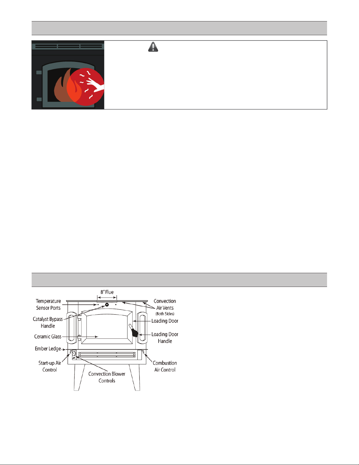
Blower is standard equipment with the Model 2500. The
Convecon Blower increases the delivery of heated air into
the home. The Convecon Blower is equipped with a Ther-
mal Switch (snap disk) which turns the blower on as the
heater warms up and offas it cools, and a 3-speed Switch to
adjust the blower speed in relaon to the current burn rate.
Addional instrucons are on Page 23.
• Set the Toggle Switch to "Therm" to allow the blower to
turn on and offautomacally. Set the Toggle Switch to
"Manual" to bypass the thermal switch.
• Use the 3-speed Switch to turn the blower On/Offand to
increase/reduce the blower speed.
• Match the Convecon Blower speed to the burn rate. Re-
duce the blower speed if cool air is coming from the vent.
C G:The Model 2500 is equipped with a clear
window which allows monitoring the condion of the fire
without the need to open the Loading Door. The transparent
ceramic material has been safety tested for impact and ther-
mal resistance, however it can be damaged if it is abused.
Inspect the ceramic glass frequently for signs of damage.
Never operate the wood heater with damaged, cracked, or
broken ceramic glass. See Page 22.
Creosote deposits will build up on the window, especially
when burning low fires. The deposits may burn offwith a
hot fire. Never use oven cleaners, harsh cleaners contain-
ing ammonia, or abrasive cleaners that may cause scratches
that can develop into cracks. Harsh chemicals can also per-
manently damage the catalyst. A simple and cost effecve
soluon is to use damp (not wet) black & white newspaper
to remove light staining. To remove heavier deposits, dip the
newsprint (or a damp cloth) in a small amount of cold wood
ash. Special glass cleaners for woodstoves, formulated to
dissolve creosote, are also available. Check that they are la-
beled as safe for use with catalyc equipped wood heaters.
A D:Remove ashes once they get 2" to 3"
deep, or deep enough to impede the air inlet located be-
neath the Loading Door opening. Remove ashes when the
fire is exnguished or burned down to embers at the end of
the charcoal stage of combuson. Use a steel rake to gather
unburned charcoal or embers to one side and leave them
in the firebox to be consumed as fuel. Remove spent ash
only, leaving @ ½" to 1" of ash and hot coals in the firebox
to insulate the ember bed and ignite fresh fuel. Again, try
to avoid shoveling up hot coals or embers with the spent
ash. Embers can stay hot for days insulated in ashes. Use a
steel shovel to carefully remove the spent ashes into a steel
container with a ght-fing lid and move the container out-
doors immediately. The closed container of ashes should
be placed on a non-combusble surface or on bare ground,
well away from any building and all combusble materials,
pending final disposal. If the ashes are to be disposed of by
burial in soil or otherwise locally dispersed, they should be
retained in the closed container unl all embers have thor-
oughly cooled. No other waste of any kind shall be placed
in this container.
Some ashes may spill while removing them from the fire-
box. Ashes can be vacuumed up once they are completely
cool but ash may pass through the filter. Special vacuums,
equipped with heat resistant filters and designed for ash
clean-up and removal, are available through your dealer.
S O:The amount and density of smoke com-
ing from the chimney is a visual indicator of how cleanly the
wood heater is burning. Develop a habit of checking the
smoke opacity regularly, and at various stages of combus-
on. With experience a quick glance can confirm proper op-
eraon or signal that something needs aenon. Modern
catalyc equipped wood heaters can burn wood very cleanly
and efficiently but, ulmately, they rely on the operator to
engage the Catalyc Combustor at the proper mes and to
adjust the combuson air properly. Timing and air sengs
are dependent on the draof the chimney, the fuel being
burned, and the stage of combuson. Ideally you will ob-
serve lile or no smoke (0% opacity). Dense smoke indicates
poor combuson. Be aware that in cold weather what looks
like smoke could be moisture vapor condensing in cold air.
C F R:When wood
is burned slowly, it produces tar and other organic vapors
which combine with moisture to form creosote. At one
me it was popular to install a very large "air-ght" wood-
stove, load it full of wood, and reduce the combuson air;
perfect condions for producing creosote. Modern catalyc
equipped wood heaters, properly operated and maintained,
burn offthe smoke and creosote that older stoves produced,
but the same elements are present. Tars and vapors, com-
bined with moisture, can condense in the chimney at tem-
peratures below @ 250°F. The resulng creosote can accu-
mulate, clinging ghtly to the flue liner and, if ignited, can
create a very hot and dangerous chimney fire.
Creosote producing tars and vapors are burned at tempera-
tures over 1100°F in the presence of the Catalyc Combustor.
The Combustor will consume the smoke and creosote pro-
ducing tars if it is properly acvated and supplied with suf-
ficient combuson air. Even sll, in a relavely cool chimney,
especially an exterior masonry chimney, the exhaust gasses
can cool before they exit the flue and some creosote will be
produced. The chimney connector and chimney should be
inspected at least once every two months during the heang
season, or more frequently as needed, to determine if creo-
sote build-up has occurred. Contact your High Valley dealer
or local chimney sweep if you are uncertain how to inspect
the venng system. Always have the chimney cleaned at the
end of the burning season or before resuming operaon.
IC C F:If your wood heater is
operated properly to maintain clean, efficient combuson,
connected to a good chimney, burning good, dry wood, and
inspected regularly, a chimney fire should be an unlikely oc-
currence. If a chimney fire does occur it can be dangerous
and frightening. Chimney fires are oen accompanied by a
loud rushing sound and, at mes, banging noises within the
chimney. Should a chimney fire occur, alert everyone in the
home and leave the building immediately. Contact the fire
department. If it appears safe to reenter the home close
the Air Control and manual damper (if so equipped) wear-
ing a heat resistant glove, to cut offair to the fire. Do not
throw water on the wood heater. Thermal shock could break
the ceramic glass causing smoke and/or ember spillage, or
otherwise damage the wood heater. Have the chimney in-
spected and cleaned or repaired as necessary before resum-
ing operaon of the wood heater.

18
P P C P S
T F S
S S.
The Bypass Damper is closed Open the Bypass Damper fully for starng and loading.
Air Controls aren't full open Open (pull-out) both Air Controls fully for startup.
The chimney is cold Use extra paper or other to warm the chimney before lighng.
The kindling is not dry Use enough fully dry sowood kindling to establish a coal bed.
It is too warm outside Wait for colder weather before lighng the fire.
The hand damper is closed Open the hand damper fully (if so equipped).
The chimney is obstructed Have the chimney, connector pipe, and cap cleaned.
T F L, S
E,
I F, '
H E.
See all of the above Use enough kindling to establish a hot fire before loading logs.
Green or wet wood Use well seasoned wood that is not wet or covered with snow.
Bypass Damper closed early Allow the Catalyst to acvate fully (500°F to 600°F).
The Air Controls are closed Allow the fire to become fully established before adjusng.
Negave house pressure Open a window. Make-up air supply may be needed.
S
L D.
The Bypass Damper is closed Open the Bypass Damper before opening the Loading Door.
The Air Controls are closed Open the Air Controls before unlatching the Loading Door.
Door opened too quickly Unlatch the Loading Door, pause, then open the door slowly.
S L
.
Bypass Damper closed early Allow the Catalyst to acvate fully (500°F to 600°F).
Catalyst obstructed The Catalyc Combustor elements may need cleaning.
T M H;
T F C
C P.
Too much combuson air Close the Start-up Air Control and use the Primary Control.
Loading Door unlatched Close and latch the Loading Door securely.
Worn Loading Door gasket Replace the Loading Door gasket.
T I
Wood heater performance issues are most oen related to poorly seasoned or wet fuel, poor chimney performance, and/or
maintenance. Wood heaters are manually operated and, as such, depend on the operator to follow good burning pracces
and to use properly seasoned cord wood of the best quality available. With experience the operator will learn to quickly
spot changes in performance that may indicate the need for chimney cleaning or other maintenance. Chronic draor smoke
leakage problems should be discussed with your High Valley dealer or a professional chimney sweep and resolved. (Refer to
Chimney Performance on Page 6.) Use well seasoned hardwood and keep it dry and protected from rain and snow with an
appropriate cover. Refer to Appendices A & B on Pages 24 & 25.
S H:Always operate the wood heater according to the guidelines on Page 16 & 17. You must develop
and use good wood burning habits; always open the Bypass Damper and Air Controls before opening the Loading Door, and
always open the Loading Door slowly to avoid pulling smoke from the firebox into the home. A modern wood heater, properly
installed and connected to a good chimney which provides adequate dra, should not leak smoke into the home. Air is drawn
into the wood heater, and into any small gaps in the connector pipe, by negave pressure (dra). If smoke is leaking into the
home from the wood heater or the connector pipe there is inadequate draor the chimney is blocked in some way. A smoke
alarm or CO detector sounding will signal smoke leakage, and they should be installed throughout your home. See Page 2. A
whiffof smoke will also alert you to the fact that there is inadequate dra. By-products of wood combuson contain carbon
dioxide, carbon monoxide, tars, water vapor, etc., but the disncve aroma of wood smoke always accompanies them. If you
are smelling wood smoke on a regular basis, not associated with lighng or loading, or your CO detector is acvated, have the
problem invesƟgated and addressed. Carbon Monoxide (CO) is parcularly dangerous. Atmospheric condions, tall struc-
tures, wind pressures, etc. can negavely affect draon occasion, but a system that consistently leaks smoke into the home
needs to be corrected. Drais measured with a manometer, which accurately measures negave pressure in "inches of water
column," to eliminate guesswork. The difference of a few hundredths of an inch of water column can spell the difference
between poor performance and clean, efficient burning. Your High Valley dealer or a chimney professional, using experience
and all of the tools available to them, should be able to diagnose the problem and recommend soluons.
Negave pressure in the home can overcome natural draand cause smoke leakage. Today's homes are constructed to
be much ghter and beer insulated than older homes. Those older homes tended to "breathe" as fresh air was drawn in
through myriad cracks to replace the air that rose up the chimney. Today well designed homes are equipped with "replace-
ment air" systems to bring fresh air into the home. Without replacement air, ght homes can inhibit chimney draand the
flow of the chimney may be reversed when a vented appliance, such as a kitchen hood or a clothes dryer, is turned on. Tight
homes and house pressures are complicated subjects, but they can be analyzed (also with manometers) and corrected. Fresh
air may need to be brought into the room with the wood heater to help relieve negave house pressure condions.

19
C I T I
C T I:A probe style thermometer is provided with the Model 2500. The thermom-
eter is used to monitor the operang temperatures of the catalyc combustor elements. Two mounting or "sampling" holes
are provided on the front of the Model 2500, located on either side of the Catalyc Bypass Handle. The choice of which sam-
pling hole to use is personal preference. Either locaon works equally well. If you tend to operate the Bypass Damper with
your right hand, the thermometer may be best located in the leside sampling hole and vice versa. To install the Catalyc
Thermometer, pry one of the metal plugs out of the sampling hole of your choice with a flat bladed screwdriver or a similar
tool. Install the bushing that is included with the Catalyc Thermometer into the ¼" sampling hole. The bushing should fit
snugly into the sampling hole. Insert the Catalyc Thermometer probe fully into the bushing unl the thermometer dial rests
against the face of the Model 2500. The probe should fit easily into the bushing and should not need to be forced.
Properly posioned, the p of the thermometer probe is now reading temperatures inside the firebox and within ½" of the
catalyc combustors. In this posion the Catalyc Thermometer can accurately measure the temperatures being generated
by the combustors. Please note that the Catalyc Thermometer is a bimetallic design, not an "instant-read" thermometer.
Allow a few minutes for the reading to stabilize. Likewise, the thermometer records temperatures between 0°F and 2000°F
on a relavely small scale. The readings are intended to show operang ranges, not minor degree variaons.
C T O: The Catalyc Thermometer is your best in-
dicator of catalyc combustor performance and condion. The catalyc combustors
must reach 500°F or more in order for them to acvate or "light-off." Be paent; it may
take 30 minutes or more to reach these temperatures from a cold start.
• Once thermometer reads between 500°F and 600°F, close the Bypass Damper to
engage the catalyc combustors.
• Connue to monitor the thermometer. If the catalyc combustors have acvated,
the temperature should connue to increase to 1000°F to 1400°F. This is the best
and most efficient operang range. Adjust the combuson air accordingly.
• If temperatures are reading 1400°F or more, reduce the combuson air seng to
improve efficiency and prevent damage to the combustors and/or the wood heater. Catalyc Probe Thermometer
D T:The Catalyc Thermometer is a useful diagnosc tool. If you have closed the Catalyc Bypass but the
temperature does not connue to rise on the Catalyc Thermometer, the bypass was closed before the combustors were
acvated. If higher temperatures than normal are needed to acvate the catalyc combustors, the combustors may need
cleaning or may be reaching the end of their service life. If the catalyc combustors will not "light-off" at any temperature the
combustors may be plugged with fly ash or creosote. Follow the instrucons on Page 20 to clean the combustors.
M:The Catalyc Thermometer requires lile or no service. According to the manufacturer, a buildup of mate-
rial on the probe is normal and does not affect the performance of the thermometer. If you do choose to clean the probe,
stove glass cleaner, made for dissolving creosote on ceramic glass, should be used to gently wipe the probe.
C T:The catalyc combustor technology used in the Model 2500 is similar in many ways to the cata-
lyc converters used on automobiles equipped with internal combuson engines. Both use a noble metal catalyst and, in the
presence of the catalyst, the by-products of combuson (in this case wood smoke) ignite at lower temperatures than they
would normally. Catalyc combustors begin with a base (substrate) of ceramic material. The ceramic is extruded into a hon-
eycomb shape, to maximize the surface area within the combustor, and then fired to make it rigid, durable, and resistant to
high temperatures. The hardened substrate is prepared with a porous base coat, to enhance bonding and increase the surface
area, and finally a coang of a noble metal catalyst, such as planum, palladium, or other, is applied. By definion the catalyst
is not consumed, and does not undergo any lasng chemical change, in the chemical reacon it increases. Theorecally the
noble metal catalyst could last indefinitely. In fact, over me some elements in wood smoke tend to bond to the noble metal,
reducing its effecveness, and fricon from smoke and ash gradually wear or "flaen" the catalyst coang.
The useful life of a catalyc combustor is esmated to be @12,000 hours, barring damage from impact or abuse. At that stage
the catalyst is expected to be @75% effecve. The combustor will take longer to acvate or "light off" and there will be a
noceable drop in heat output. The number of years service you can expect from catalyc combustors will depend on where
you live and how you use your wood heater. A serious wood burner, living up north, may expect to get three to four years
service, while a casual burner in a more temperate climate may get ten years or more. In any climate, the key to maximum
combustor life rests with the operator. At the risk of redundancy; burning only well seasoned cord wood is the best advice.
If you are new to catalyc wood heaters, follow the instrucons found in this manual and develop good burning habits. It
should not take long to develop your wood burning skills. Developing a rhythm for loading fresh fuel and learning the best
me to engage the catalyst comes with repeon. In fact, it may be easier for someone who is unfamiliar with wood heat-
ers to develop a roune than an experienced wood burner who has operated other types of wood heaters. The experienced
user may need to unlearn, or change, their burning roune or habits. Regardless of experience, rest assured it is not difficult.
Burning good, well seasoned cord wood is the main ingredient for success. Never burn painted, contaminated, or pressure
treated wood; or any other prohibited materials listed on Page 2. Take full advantage of the long burning capability of your
catalyc equipped wood heater. A cataly
c equipped wood heater works best with a comfortably full load of cord wood in
the firebox. (But don't "jam" the firebox full.) Allow the catalyc combustors to acvate, close the Bypass Damper, set the
Combuson Air for a low to medium fire, enjoy the warmth unl the fire has burned down to a good bed of coals, and reload.

20
C C:The catalyc combustor elements are held firmly in the Combustor Housing with gaskets that expand
when exposed to heat. Unless the combustors are worn out or severely damaged there is no need to remove them. The
gaskets lose flexibility aer they have expanded and are not reusable. It is not normally necessary to clean the boom of the
catalyc combustors. Vacuum or brush out any ash residue in the boom of the Combustor Housing. Resist inserng any-
thing into the individual holes in the honeycomb. Even sotools can damage or remove the catalyst coang. If a few holes
are plugged with spent ash that resists vacuuming, clear the holes very carefully with a pipe cleaner as necessary. Never insert
hard tools, probes, or brushes into the holes in the catalyc combustor. Do not blow out the combustors with compressed
air. A powerful stream of air can remove the catalyst coang. In addion, most air compressors are oil lubricated and create
condensaon in the air tank. Air from a shop air compressor can contaminate the catalyst with oil and/or water. Once the
catalyc combustors are cleaned sasfactorily of excess ash and soot, replace the Combustor Housing in the firebox.
Catalyc Combustor Housing Locaon
The Combustor Housing is held in place with four (4) nuts and studs.
Two of the nuts are visible on the front edge of the housing; the other
two (2) nuts are in the same relave posions on the back of the
housing, but are not readily visible. The Combustor Housing is fairly
large (4” W x 20” L X 2½” H) and quite heavy. Have a helper support
the housing, or cut temporary supports to length from short pieces of
2 x 4, 4 x 4, or similar material. The supports should fit loosely under
the housing. Do not wedge the housing ghtly.
A ratchet, a 9/16" socket, and an extension are recommended for re-
moving the nuts. Loosen the four (4) nuts evenly, but do not remove
them unl the housing is supported. With the Combustor Housing
supported, remove the four (4) nuts. Do not aempt to remove the
studs. Lower the housing and remove it from the Firebox. Be aware
that the Combustor Housing may contain ashes, soot, and creosote.
C C R C
I: Handle the Combustor Housing carefully. Remove the housing to a convenient work surface that has been pro-
tected with plasc sheeng, newspaper, or the like. Connue to wear a good dust mask and gloves. The top surfaces of the
catalyc combustors are now exposed in the housing. Do not p the housing up-side-down. Do not aempt to remove the
combustors from the housing at this stage. Make a careful visual inspecon of the catalyc combustors. Ash and soot residue
on the combustors is normal and it can be gently removed with a sopaint brush and/or a vacuum cleaner with a sobrush
aachment. With the loose ash removed, connue to inspect the catalyc combustor elements. If only normal ash and soot
accumulaon are observed, finish cleaning the combustors following the instrucons below, and replace the Catalyc Hous-
ing in the firebox. If any condion other than a normal accumulaon of ash residue is observed, refer to the chart below, and
addional informaon on Page 21, to help idenfy and correct the cause of the abnormal condion.
C C H R: Two catalyc combustor elements are fied into individual cavies in the top
of the Combustor Housing. The Combustor Housing is located just inside the Loading Door, secured to the top of the Firebox.
The housing assembly is heavy and it is likely to be dusty and/or dirty. Wear a good dust mask and gloves. Handle the Com-
bustor Housing with care. Rough handling or impact can easily damage the catalyc combustor elements.
C P C P S
A S Some ash & soot are normal
by-products of combuson.
Gently remove ash and soot residue with a sobrush or a
vacuum with a brush aachment and reinstall the combustors.
C
S
Engaging the Bypass Damper
before ashes have seled.
Close the Start-up Air Control and wait for disturbed ashes to
sele before closing the By-pass Damper.
C C
C
The Bypass Damper is closed
before the combustors are
acvated fully.
Always monitor the temperature of the combustors to ensure
that the temperature connues to rise aer the bypass is closed.
Do not try to scrape offcreosote. Reinstall the combustors and
build a hoer than normal fire. Try engaging the combustors. If
the temperature rises, operate at @1400° to burn offdeposits.
Wet or unseasoned wood.
C C
-
Thermal shock caused by
moisture in fresh wood.
Allow enough me for moisture to be driven offof wet or un-
seasoned wood before engaging a hot acvated catalyst.
Flame impingement on the
catalyc elements.
Do not overfill the firebox or build a roaring fire up close to the
Catalyc Combustor Housing.
P Aggressive cleaning. Do not use hard tools, sffbrushes, or compressed air to clean
the catalyst and do not insert tools into the honeycomb.
C C M:Catalyc combustors should be inspected and cleaned at least annually, when-
ever the chimney is cleaned, and/or whenever decreased performance is suspected. Whether you perform roune mainte-
nance yourself or rely on a cerfied professional, regular maintenance ensures maximum efficiency from your wood heater.
Other manuals for 2500
1
Table of contents
Other High Valley Wood Stove manuals
Popular Wood Stove manuals by other brands

HASE
HASE MERIDA - manual

Invicta
Invicta REMILLY Specific User and Installation Manual

FRANCO BELGE
FRANCO BELGE Limousin Technical manual

Lennox Hearth Products
Lennox Hearth Products STRIKER S160 Installation and operation manual

United States Stove
United States Stove Defender II owner's manual

RAIS
RAIS 900 user manual

Lopi
Lopi Endeavor ND owner's manual

Quadra-Fire
Quadra-Fire Isle Royale instructions

Heatilator
Heatilator Builder's Choice BCDV36 Installation & operating instructions

HWAM
HWAM Autopilot IHS quick guide

Escea
Escea TFS Series Installation instructions and user guide

KENT
KENT EVOLUTION4 INSERT owner's manual