User Manual of the DS-1004K keyboard 7
Button Description
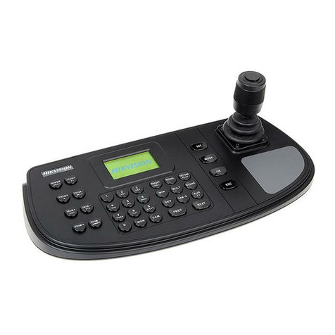
DVR control mode: change the tab menu
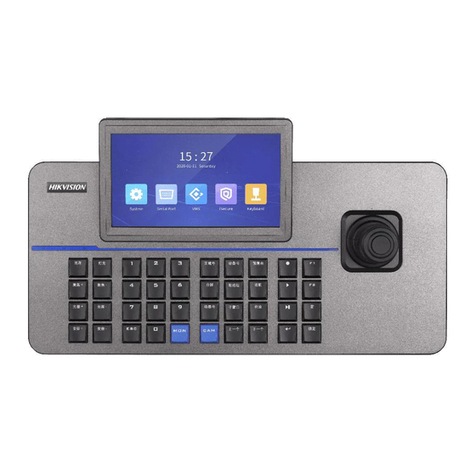
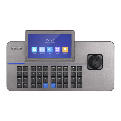
NEXT The next item, can be a channel or menu setting field.
LAST The pre ious item, can be a channel or menu setting field.
MON When controlling the VMS or analog matrix, press this button to choose the monitor.
CAM When controlling the VMS or analog matrix, press this button to choose the camera.
MODE Press to switch the control mode of the keyboard
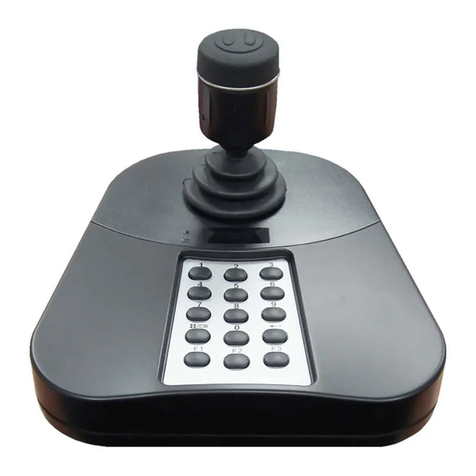
Numeric & characters buttons
(0-9) Input the number or character; choose the li e iew or playback channel.
CLEAR Clear the numbers input and exit.
ENTER Enter
IRIS+/EDIT PTZ control mode: iris+
DVR control mode: enable editing
IRIS-/PTZ PTZ control mode: iris-
DVR control mode: show the PTZ control menu
FOCUS+/A PTZ control mode: focus+
DVR control mode: switch the input methods
FOCUS-/PREV PTZ control mode: focus-
DVR control mode: switch the screen display.
ZOOM+ PTZ control mode: zoom+
ZOOM-/ MAIN/SPOT PTZ control mode: zoom-
DVR control mode: switch between main and auxiliary mode
LIGHT/F1 PTZ control mode: turn on the light
WIPER/MENU PTZ control mode: enable wiper
DVR control mode: open the main men
2.3
Joystick Function
Gra hic O eration Function
Up PTZ control mode: Mo e the PTZ up.
DVR control mode: Fast Play when playback, or na igate to the pre ious item when
operating the menu.
Down PTZ control mode: Mo e the PTZ down.
DVR control mode: Slow play when playback, or na igate to the next item when
operating the menu.
Left PTZ control mode: Mo e the PTZ to the left.
DVR control mode: Skip backward when playback, or na igate to the pre ious menu
when operating the menu.
Right PTZ control mode: Mo e the PTZ right.
DVR control mode: Skip forward when playback, or na igate to the next menu when
operating the menu.
Left Rotate Zoom in
Right Rotate Zoom out
Notes :
The joystick realizes pan and tilt mo ement at 8 directions.
The 4-axis joystick can be used to control the zoom; and the central button used as Enter button and to realize picture capture as well.
