-1-
WARNING: Be sure to remove the battery from the main body before starting repair or
maintenance work. If the switch is activated inadvertently with the battery still
mounted on the main body, the motor may turn unexpectedly and could cause serious
injury.
1. Precautions on disassembly and reassembly
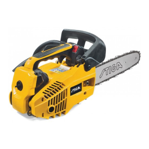
[Bold] numbers in the description below correspond to the item numbers in the parts list and exploded
assembly diagram for the Model CS 3630DA.
NOTE: Remove all residual chain oil from the oil tank before disassembling the chain saw. If the
tank cap is tightened too hard and it is difficult to loosen, insert a flat-blade screwdriver
into the groove and rotate it to facilitate removal. There are also cases in which the chain oil
may soil the work area. Put a waste cloth under the chain saw before disassembling.
1. Removing the carbon brush
(1) Remove the two Brush Caps [85] with a flat-blade screwdriver and remove the Carbon Brush (1 pair)
[84].
(2) Do not apply excessive pressure to the Brush Holders [83] and [89] when removing the Carbon Brush
(1 pair) [84]. Otherwise, the Brush Holders [83] and [89] may be damaged.
2. Removing the saw chain and chain bar
(1) Loosen the Hex. Socket Hd. Bolt M5 x 20 [17] with the Hex. Bar Wrench 4 mm [504]. Then loosen the
Knob [13] and remove the Chain Side Cover [18]. If necessary, rotate the Tension Dial [14]
counterclockwise slightly to reduce tension on the saw chain to facilitate this.
(2) Remove the Saw Chain [27] and the Chain Bar [28] together.
3. Removing the clutch housing
(1) Hold the sprocket of the Clutch Housing [12] in place with pliers. Loosen and remove the Lock Nut
(Left Hand) M8 [9] by rotating it clockwise. Remove the Super Lock Washer M8 [10] and the Side
Plate [11]. Then remove the Clutch Housing [12].
4. Disassembling the housing. handle cover set
(1) Push the Brake Handle [91] forward to OFF position. Then the inner diameter of the Brake Band [5] is
smaller than before and it is easy to disassemble or reassemble.
(2) Remove the eight Tapping Screws D4 x 20 [30], Tapping Screw D3 x 16 [35], and Nozzle [53]. Then
the Housing. Handle Cover Set [37] can be removed with all internal parts in it.
(3) Do not lose the Trigger [72], Spring [63], and Lock Button [64] when disassembling the Housing.
Handle Cover Set [37].
Disassembly
REPAIR GUIDE
