HikRobot SC2000 Series User manual

SC2000 Series Vision Sensor
User Manual

SC2000 Series Vision Sensor User Manual
i
Legal Information
© 2020 Hangzhou Hikrobot Technology Co., Ltd. All rights reserved.
About this Manual
The Manual includes instructions for using and managing the Product. Pictures, charts, images and
all other information hereinafter are for description and explanation only. The information
contained in the Manual is subject to change, without notice, due to firmware updates or other
reasons. Please find the latest version of this Manual at the Hikrobot website
(https://en.hikrobotics.com).
Please use this Manual with the guidance and assistance of professionals trained in supporting the
Product.
Trademarks
and other Hikrobot's trademarks and logos are the properties of Hikrobot in
various jurisdictions.
Other trademarks and logos mentioned are the properties of their respective owners.
Disclaimer
TO THE MAXIMUM EXTENT PERMITTED BY APPLICABLE LAW, THIS MANUAL AND THE PRODUCT
DESCRIBED, WITH ITS HARDWARE, SOFTWARE AND FIRMWARE, ARE PROVIDED "AS IS" AND
"WITH ALL FAULTS AND ERRORS". HIKROBOT MAKES NO WARRANTIES, EXPRESS OR IMPLIED,
INCLUDING WITHOUT LIMITATION, MERCHANTABILITY, SATISFACTORY QUALITY, OR FITNESS FOR
A PARTICULAR PURPOSE. THE USE OF THE PRODUCT BY YOU IS AT YOUR OWN RISK. IN NO EVENT
WILL HIKROBOT BE LIABLE TO YOU FOR ANY SPECIAL, CONSEQUENTIAL, INCIDENTAL, OR INDIRECT
DAMAGES, INCLUDING, AMONG OTHERS, DAMAGES FOR LOSS OF BUSINESS PROFITS, BUSINESS
INTERRUPTION, OR LOSS OF DATA, CORRUPTION OF SYSTEMS, OR LOSS OF DOCUMENTATION,
WHETHER BASED ON BREACH OF CONTRACT, TORT (INCLUDING NEGLIGENCE), PRODUCT
LIABILITY, OR OTHERWISE, IN CONNECTION WITH THE USE OF THE PRODUCT, EVEN IF HIKROBOT
HAS BEEN ADVISED OF THE POSSIBILITY OF SUCH DAMAGES OR LOSS.
YOU ACKNOWLEDGE THAT THE NATURE OF INTERNET PROVIDES FOR INHERENT SECURITY RISKS,
AND HIKROBOT SHALL NOT TAKE ANY RESPONSIBILITIES FOR ABNORMAL OPERATION, PRIVACY
LEAKAGE OR OTHER DAMAGES RESULTING FROM CYBER-ATTACK, HACKER ATTACK, VIRUS
INSPECTION, OR OTHER INTERNET SECURITY RISKS; HOWEVER, HIKROBOT WILL PROVIDE TIMELY
TECHNICAL SUPPORT IF REQUIRED.
YOU AGREE TO USE THIS PRODUCT IN COMPLIANCE WITH ALL APPLICABLE LAWS, AND YOU ARE
SOLELY RESPONSIBLE FOR ENSURING THAT YOUR USE CONFORMS TO THE APPLICABLE LAW.
ESPECIALLY, YOU ARE RESPONSIBLE, FOR USING THIS PRODUCT IN A MANNER THAT DOES NOT
INFRINGE ON THE RIGHTS OF THIRD PARTIES, INCLUDING WITHOUT LIMITATION, RIGHTS OF
PUBLICITY, INTELLECTUAL PROPERTY RIGHTS, OR DATA PROTECTION AND OTHER PRIVACY RIGHTS.
YOU SHALL NOT USE THIS PRODUCT FOR ANY PROHIBITED END-USES, INCLUDING THE
DEVELOPMENT OR PRODUCTION OF WEAPONS OF MASS DESTRUCTION, THE DEVELOPMENT OR
PRODUCTION OF CHEMICAL OR BIOLOGICAL WEAPONS, ANY ACTIVITIES IN THE CONTEXT RELATED

SC2000 Series Vision Sensor User Manual
ii
TO ANY NUCLEAR EXPLOSIVE OR UNSAFE NUCLEAR FUEL-CYCLE, OR IN SUPPORT OF HUMAN
RIGHTS ABUSES.
THE PERFORMANCE DATA IN THIS PUBLICATION IS BASED ON HIKROBOT'S INTERNAL
RESEARCH/EVALUATION. ACTUAL DATA MAY VARY DEPENDING ON SPECIFIC CONFIGURATIONS
AND OPERATING CONDITIONS AND HIKROBOT SHALL NOT BEAR THE CONSEQUENCES ARISING
THEREFROM.
IN THE EVENT OF ANY CONFLICTS BETWEEN THIS MANUAL AND THE APPLICABLE LAW, THE LATER
PREVAILS.
Regulatory Information
FCC Information
Please take attention that changes or modification not expressly approved by the party
responsible for compliance could void the user’s authority to operate the equipment.
FCC compliance: This equipment has been tested and found to comply with the limits for a Class A
digital device, pursuant to part 15 of the FCC Rules. These limits are designed to provide
reasonable protection against harmful interference when the equipment is operated in a
commercial environment. This equipment generates, uses, and can radiate radio frequency energy
and, if not installed and used in accordance with the instruction manual, may cause harmful
interference to radio communications. Operation of this equipment in a residential area is likely to
cause harmful interference in which case the user will be required to correct the interference at
his own expense.
—Reorient or relocate the receiving antenna.
—Increase the separation between the equipment and receiver.
—Connect the equipment into an outlet on a circuit different from that to which the receiver is
connected.
—Consult the dealer or an experienced radio/TV technician for help.
FCC Conditions
This device complies with part 15 of the FCC Rules. Operation is subject to the following two
conditions:
1. This device may not cause harmful interference.
2. This device must accept any interference received, including interference that may cause
undesired operation.
EU Conformity Statement
This product and - if applicable - the supplied accessories too are marked
with "CE" and comply therefore with the applicable harmonized European
standards listed under the EMC Directive 2014/30/EU, the RoHS Directive
2011/65/EU.

SC2000 Series Vision Sensor User Manual
iii
2012/19/EU (WEEE directive): Products marked with this symbol cannot be
disposed of as unsorted municipal waste in the European Union. For proper
recycling, return this product to your local supplier upon the purchase of
equivalent new equipment, or dispose of it at designated collection points.
For more information see: http://www.recyclethis.info
2006/66/EC (battery directive): This product contains a battery that cannot
be disposed of as unsorted municipal waste in the European Union. See the
product documentation for specific battery information. The battery is
marked with this symbol, which may include lettering to indicate cadmium
(Cd), lead (Pb), or mercury (Hg). For proper recycling, return the battery to
your supplier or to a designated collection point. For more information see:
http://www.recyclethis.info
Symbol Conventions
The symbols that may be found in this document are defined as follows.
Symbol
Description
Danger
Indicates a hazardous situation which, if not avoided, will or could
result in death or serious injury.
Caution
Indicates a potentially hazardous situation which, if not avoided,
could result in equipment damage, data loss, performance
degradation, or unexpected results.
Note
Provides additional information to emphasize or supplement
important points of the main text.
Available Model
This manual is applicable to the SC2000 Series Vision Sensor.
Safety Instruction
These instructions are intended to ensure that the user can use the device correctly to avoid
danger or property loss.
Laws and Regulations
The device should be used in compliance with local laws, electrical safety regulations, and fire
prevention regulations.

SC2000 Series Vision Sensor User Manual
iv
Power Supply
●When wiring or dismounting, make sure that the device power is cut off, and do not operate
under electrification.
●Avoid contact with exposed circuit. When the device is powered on, avoid contact with exposed
junctions and parts.
●Use the power adapter provided by the regular manufacturer.
●Do not connect multiple devices to one power adapter, to avoid over-heating or fire hazards
caused by overload.
●Make sure the plug is properly connected to the power socket.
Transportation
●The device contains precision optical components and electronic components. During
transportation, storage and installation, incorrect operations like heavy pressure and violent
vibration should be avoided. Otherwise, the device may be damaged.
●Avoid sudden collision, and pack the device with the accompanied carton and cushioning
material or similar package.
Using Environment
●In order to reduce the risk of fire or electric shock, do not let the device get wet or damp.
●Do not drop objects onto the device and avoid vigorous vibration.
●Keep the device away from magnetic interference.
●Do not use the device in extremely heat, extremely cold, dusty environment, corrosive
environment or high humidity environment.
●Do not aim the device lens at objects of strong light, such as the sun and incandescent lamp.
Otherwise, the lens may be damaged.
●The device should be stored in dry environment without corrosive gas. Avoid placing the device
in direct sunlight and poorly ventilated locations, or near heat sources such as heater or heating
(ignoring this warning may lead to fire hazards).
●Do not operate in explosive environment.
●Keep the surrounding area well ventilated to avoid heat accumulation. Do not contact the
radiator directly to avoid scald.
Electrostatic Protection
●Remove all conductive objects (such as jewelry, watch, etc.) on the device body before touching
the device, and touch the grounding metal bracket by hand to release the static electricity.
●It is suggested to wear anti-static suit to prevent damage to the equipment caused by static
electricity.
●When installing or maintaining the device, please wear anti-static wristband or anti-static
gloves. Make sure that the wristband is tightly attached to the skin and is reliably grounded.
●It is forbidden to touch exposed circuit boards with bare hands. Static electricity generated by
human body may damage electrostatic sensitive components on circuit boards.
●When touching electrostatic sensitive components or devices, proper grounding measures must
be taken.
●Put electrostatic sensitive components into anti-static bags for protection.

SC2000 Series Vision Sensor User Manual
v
●It is suggested to place humidifier in dry environment to maintain suitable humidity and reduce
static electricity generation.
Maintenance
●If the device is not working properly, contact the store or the nearest service center. Do not
disassemble or modify the device in any way. (The company does not bear any liability for any
problem arising from unauthorized modification or maintenance).
●Properly preserve all the original packaging materials of the device so that when problems arise,
the device can be packed with packaging materials and sent to the agent or returned to the
manufacturer for processing. The company does not bear any liability for accidental damage
during transportation caused by non-original packaging.
●This product is a precision electronic device, no components can be maintained by user, please
do not disassemble the device arbitrarily.
Cleaning
Do not touch the image sensor directly. If the sensor needs to be cleaned, use a clean rag and wet
it with alcohol, then gently wipe off the dirt; if the device is not in use, cover the image sensor with
dust cover for protection.
Installation
Please do not install the device on vibrating surface or places that are vulnerable to impact.
Personnel Requirement
Quality requirements for installation and maintenance personnel: qualification certificate or
working experience in weak current system installation and maintenance, and relevant working
experience and qualifications. Besides, the personnel must possess the following knowledge and
operation skills:
●The basic knowledge and operation skills of low voltage wiring and low voltage electronic circuit
connection.
●The ability to comprehend the contents of this manual.
Contact Information
Hangzhou Hikrobot Technology Co., Ltd.
No. 399 Danfeng Road, Binjiang District, Hangzhou, 310051, China
E-mail: tech_support@hikrobotics.com
Website: https://en.hikrobotics.com/

SC2000 Series Vision Sensor User Manual
vi
Contents
Chapter 1 Overview........................................................................................................................ 1
1.1 Introduction ...................................................................................................................... 1
1.2 Key Feature ....................................................................................................................... 1
Chapter 2 Appearance.................................................................................................................... 2
Chapter 3 17-Pin Interface.............................................................................................................. 4
Chapter 4 I/O Wiring ...................................................................................................................... 6
4.1 Input ................................................................................................................................. 6
4.2 Output .............................................................................................................................. 7
4.3 Input Wiring ...................................................................................................................... 9
4.4 Output Wiring ................................................................................................................. 10
4.5 RS-232 Serial Port ........................................................................................................... 11
Chapter 5 Installation ................................................................................................................... 13
5.1 Installation Preparation .................................................................................................. 13
5.2 Install Device................................................................................................................... 13
Chapter 6 Access Device via Web Browser ................................................................................... 14
6.1 Search Device via Camera Search Tool............................................................................ 14
6.2 Access via Web Browser ................................................................................................. 14
Chapter 7 Solution Settings .......................................................................................................... 16
7.1 Camera Settings .............................................................................................................. 16
7.1.1 Set Frame Rate ..................................................................................................... 16
7.1.2 Set Gain ................................................................................................................ 17
7.1.3 Set Exposure Mode .............................................................................................. 17
7.1.4 Set Brightness....................................................................................................... 17
7.1.5 Set Light Source.................................................................................................... 18
7.1.6 Set Image ............................................................................................................. 19
7.2 Image Acquisition Settings.............................................................................................. 21
7.2.1 Set Trigger Mode.................................................................................................. 21
7.2.2 Enable Internal Trigger Mode............................................................................... 21
7.2.3 Enable External Trigger Mode .............................................................................. 22

SC2000 Series Vision Sensor User Manual
vii
7.2.4 Set Related Parameters about External Trigger Mode ......................................... 23
7.2.5 Enable Communication Trigger Mode.................................................................. 24
7.3 Input and Output (IO) Settings........................................................................................ 25
7.4 Tool Settings ................................................................................................................... 25
7.4.1 Feature Matching ................................................................................................. 26
7.4.2 Fixture Settings .................................................................................................... 29
7.4.3 Find Circle............................................................................................................. 30
7.4.4 Find Line ............................................................................................................... 32
7.4.5 Brightness Measure.............................................................................................. 34
7.4.6 Blob ...................................................................................................................... 35
7.4.7 Find Edge Width ................................................................................................... 37
7.4.8 L2L Measure ......................................................................................................... 39
7.4.9 P2L Measure......................................................................................................... 40
7.4.10 Image Savings..................................................................................................... 40
7.4.11 N-Point Calibration............................................................................................. 41
7.4.12 Coordinate Conversion....................................................................................... 43
7.4.13 Color Extraction.................................................................................................. 44
7.4.14 Color Measurement ........................................................................................... 45
7.4.15 Color Conversion ................................................................................................ 45
7.4.16 Color Recognition ............................................................................................... 46
7.4.17 Format Tool........................................................................................................ 48
7.4.18 Logic Tool ........................................................................................................... 49
7.5 Communication Settings................................................................................................. 49
7.5.1 UDP ...................................................................................................................... 49
7.5.2 TCP Client ............................................................................................................. 50
7.5.3 TCP Server ............................................................................................................ 51
7.5.4 Serial .................................................................................................................... 51
7.5.5 IO Communication ............................................................................................... 52
7.5.6 FTP........................................................................................................................ 53
7.5.7 Modbus ................................................................................................................ 54
7.5.8 Profinet ................................................................................................................ 56

SC2000 Series Vision Sensor User Manual
viii
7.5.9 Ethernet/IP........................................................................................................... 57
7.6 Solution Completion ....................................................................................................... 57
Chapter 8 Solution Operation....................................................................................................... 59
8.1 Control Solution .............................................................................................................. 59
8.2 View Solution Status ....................................................................................................... 59
8.3 Manage Solution............................................................................................................. 60
8.4 View Camera Info............................................................................................................ 61
8.5 Operate Image ................................................................................................................ 61
Chapter 9 System and Maintenance............................................................................................. 63
9.1 Permission and Password Management......................................................................... 63
9.1.1 Set Admin Password ............................................................................................ 63
9.1.2 Set Technician Permission and Password............................................................. 63
9.2 Image Saving Management............................................................................................. 64
9.3 Test Library Management............................................................................................... 64
9.4 Synchronize Time............................................................................................................ 65
9.5 System Maintenance ...................................................................................................... 66
9.6 View Log ......................................................................................................................... 67
9.7 View System Version ...................................................................................................... 68
Chapter 10 FAQ (Frequently Asked Question).............................................................................. 69
10.1 Why the client software cannot list cameras? .............................................................. 69
10.2 Why the image is not smooth in live view? .................................................................. 69
10.3 Why the image is very dark?......................................................................................... 69
10.4 Why there is no image in live view?.............................................................................. 69
10.5 What can I do if I forget the login password? ............................................................... 70
Chapter 11 Revision History ......................................................................................................... 71

SC2000 Series Vision Sensor User Manual
1
Chapter 1 Overview
1.1 Introduction
The vision sensor uses the sensor and optical components to acquire object images, and it adopts
built-in location and measurement algorithms to detect object's dimension, location, etc. It has
multiple vision tools, such as, feature matching, blob, calibration transformation, color extraction,
etc., to realize different applications.
The vision sensor is able to acquire, process and output images, and detection results can be
output via the UDP, TCP, FTP, Serial, Modbus, Profinet, and other communication methods. You
can configure and operate solutions of the vision sensor via web based interface. It is applicable to
consumer electronics, food and beverage, pharmaceutical, automobile, and other industries.
1.2 Key Feature
●Adopts embedded hardware platform for high-speed image processing.
●Adopts built-in position and measurement algorithm to detect object's position, etc.
●Multiple IO interfaces for input and output signals.
●Multiple indicators for displaying device status.
●Adopts light cup to ensure uniform brightness in the illuminated area.
●Supports multiple communication protocols, including TCP, UDP, Serial, IO, Modbus, PROFINET,
Ethernet/IP, FTP, etc.
SC2000 Series Vision Sensor User Manual
2
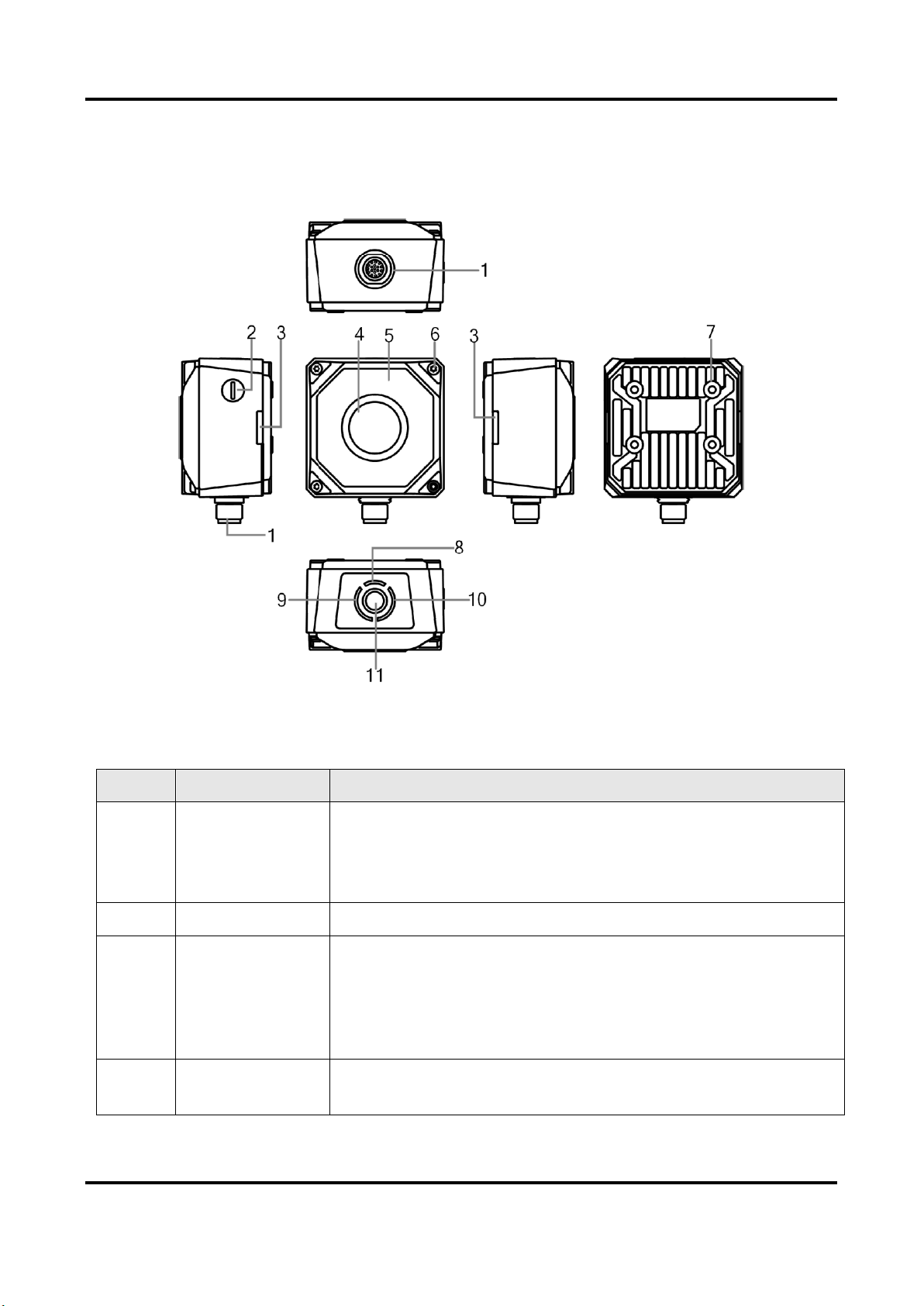
Chapter 2 Appearance
Figure 2-1 Appearance
Table 2-1 Description
No.
Name
Description
1
17-Pin Interface
It provides power, input/output, Ethernet, and serial port signal.
The interface is designed with screw threads to tighten
connection between the device and cable, and thus avoiding
influence caused by vibration.
2
Focus Knob
It is used to adjust focal length manually.
3
OK/NG Indicator
It indicates the result of solution.
●The green indicator lights when the solution result is OK.
●The red indicator lights when the solution result is NG.
●When switching solutions, the indicators both light. After
switching, the indicators both are unlit.
4
Lens Cap
It can be replaced with other lens cap. Polarization lens cap is
optional.

SC2000 Series Vision Sensor User Manual
3
No.
Name
Description
5
Light Source
The device has 8 LED lamps providing light, and the light source is
white spotlight by default. You can select wide-angle or spotlight
lamp, and white, red, blue or near-infrared is optional.
6
Screw
It refers to the screw between device body and lens cap.
7
Screw Hole
It is used to fix the device to installation position. You should use
M4 screw.
8
PWR Indicator
It is the power indicator. The indicator is green when the device
operates normally. Otherwise, it is red.
9
STS Indicator
It is the status indicator. The indicator is green when the solution
operates normally. Otherwise, it is red.
10
LNK Indicator
It is network status indicator. The indicator is flashing green when
the network transmission is normal. Otherwise, it is unlit.
11
Button
It is used to trigger device solution operation.

SC2000 Series Vision Sensor User Manual
4
Chapter 3 17-Pin Interface
Read the following section to get definitions of 17-pin interface.
1
10
9
76
4
3
16
15
14
2
12
17
13
5
8
11
Figure 3-1 17-Pin Interface
Table 3-1 Pin Definitions
No.
Signal
I/O Signal Source
Description
1
POWER_IN
--
Direct current power supply positive
2
I/O_1
Line 3 signal line
Can be configured as input or output
3
DO_2
Line 7 signal line
Opto-isolated output
4
RS-232 TX
--
RS-232 serial port output
5
RS-232 RX
--
RS-232 serial port input
6
MDI0+
--
Fast Ethernet signal MDI0+
7
MDI1-
--
Fast Ethernet signal MDI1-
8
DO_0
Line 5 signal line
Opto-isolated output
9
I/O_0
Line 2 signal line
Can be configured as input or output
10
DO_1
Line 6 signal line
Opto-isolated output
11
GND
Signal ground
Direct current power supply negative
12
Reserved
13
I/O_2
Line 4 signal line
Can be configured as input or output
14
MDI0-
--
Fast Ethernet signal MDI0-
15
MDI1+
--
Fast Ethernet signal MDI1+

SC2000 Series Vision Sensor User Manual
5
No.
Signal
I/O Signal Source
Description
16
DI_0
Line 0 signal line
Opto-isolated input
17
DI_1
Line 1 signal line
Opto-isolated input
Note
●You should refer to the table above and the label attached to the power and I/O cable to wire
the device.
●It is recommended to use the supplied 17-pin cable. The 6th, 7th, 14th, and 15th pin have been
made as RJ45 connector. The lines of other pins should be wired according to the actual
demands.
SC2000 Series Vision Sensor User Manual
6
Chapter 4 I/O Wiring
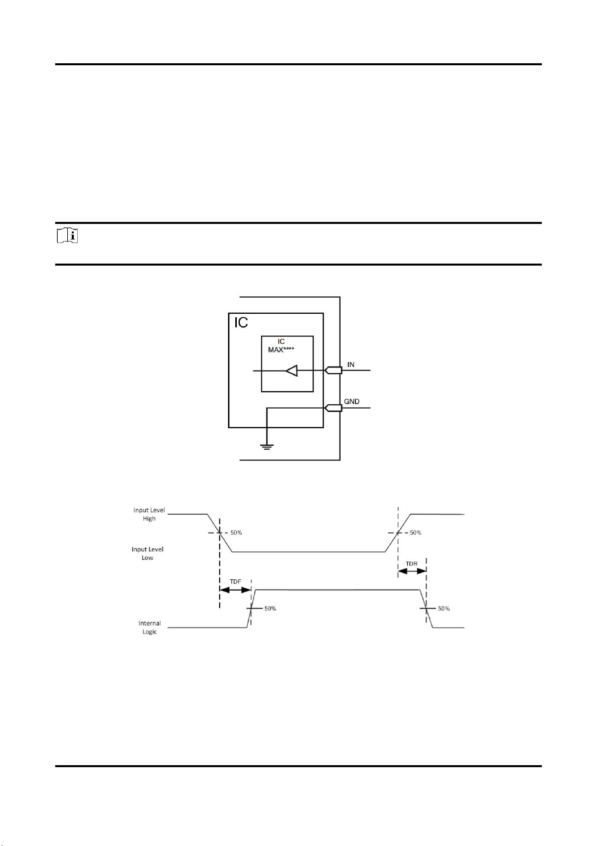
4.1 Input
The device's Line 0/1 is input, and Line 2/3/4 are bi-directional I/O(s) that can be set as input. The
internal circuit of input signal is as follows.
Note
The maximum input current of input signal is 25 mA.
Figure 4-1 Internal Circuit of Input Signal
Figure 4-2 Input Logic Level

SC2000 Series Vision Sensor User Manual
7
Table 4-1 Input Electrical Feature
Parameter Name
Parameter Symbol
Value
Input Logic Level Low
VL
0 VDC to 9 VDC (VCC=24 VDC)
0 VDC to 5.4 VDC (VCC=12
VDC)
Input Logic Level High
VH
11 VDC to 24 VDC (VCC=24
VDC)
7.56 VDC to 12 VDC (VCC=12
VDC)
Input Falling Delay
TDF
1.3 μs to 3.5 μs
Input Rising Delay
TDR
1.3 μs to 3.5 μs
Note
●VCC stands for Volt Current Condenser, and it is the device's input voltage.
●The breakdown voltage is 36 VDC, and keep voltage stable.
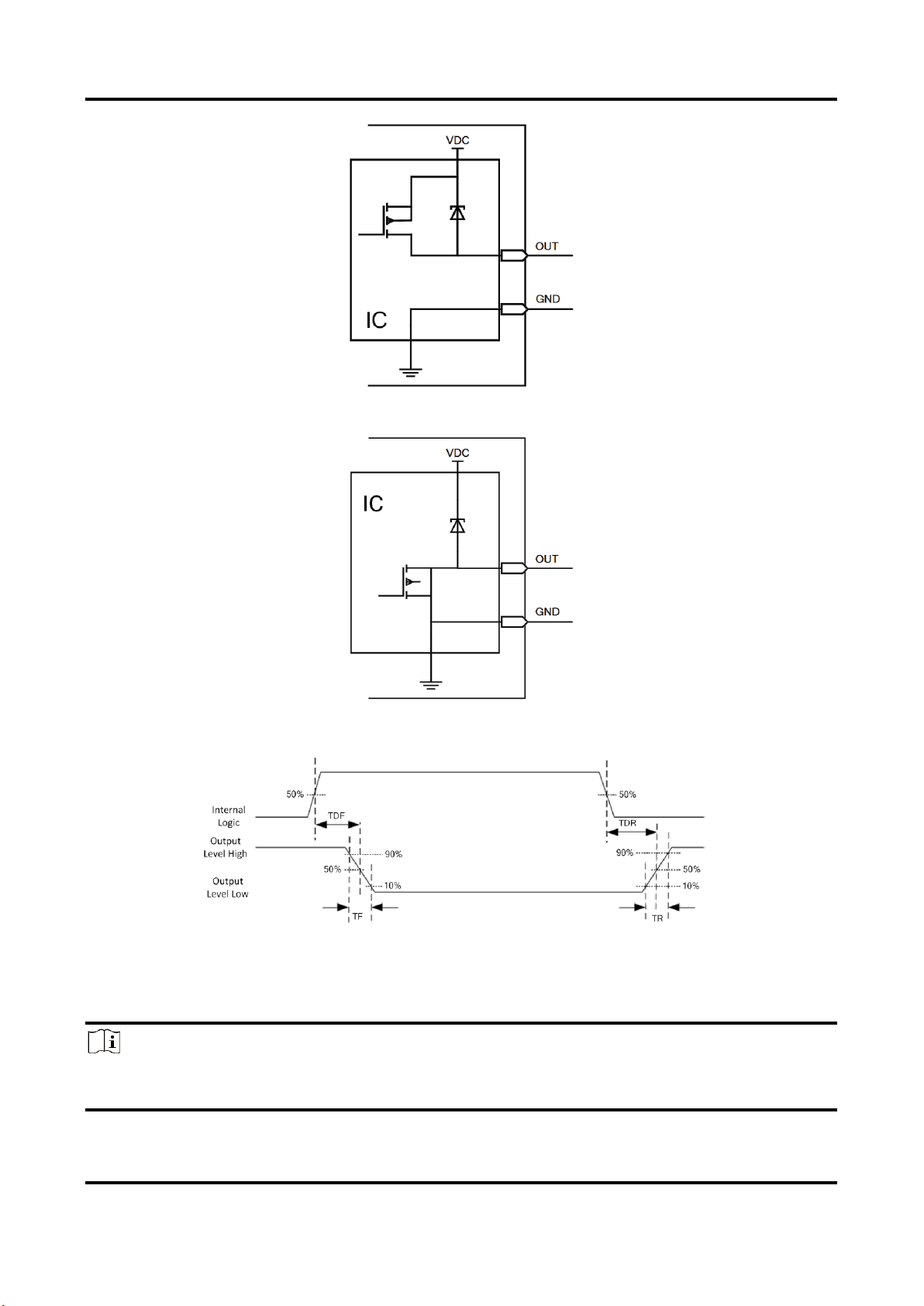
4.2 Output
The device's Line 5/6/7 are outputs, and Line 2/3/4 are bi-directional I/O that can be set as
outputs. The type of output signal can be set as PNP or NPN via web parameter. When the output
signal is PNP or NPN, the respective internal circuit is as follows.
Note
The maximum output current of output signal is 200 mA.
SC2000 Series Vision Sensor User Manual
8
Figure 4-3 Internal Circuit of PNP Output Signal
Figure 4-4 Internal Circuit of NPN Output Signal
Figure 4-5 Output Logic Level
When the external voltage and resistance is 12 VDC and 1 KΩ respectively, opto-isolated output
electrical feature is as follows.
Note
With different external voltage and resistance, the corresponding current and output logic level
low may have small change.
SC2000 Series Vision Sensor User Manual
9
Table 4-2 Output Electrical Feature
Parameter Name
Parameter Symbol
Value
Output Logic Level Low
VL
212 mV
Output Logic Level High
VH
11.8 VDC
Output Falling Delay
TDF
0.4 μs
Output Rising Delay
TDR
0.4 μs
Output Falling Time
TF
0.4 μs
Output Rising Time
TR
0.4 μs
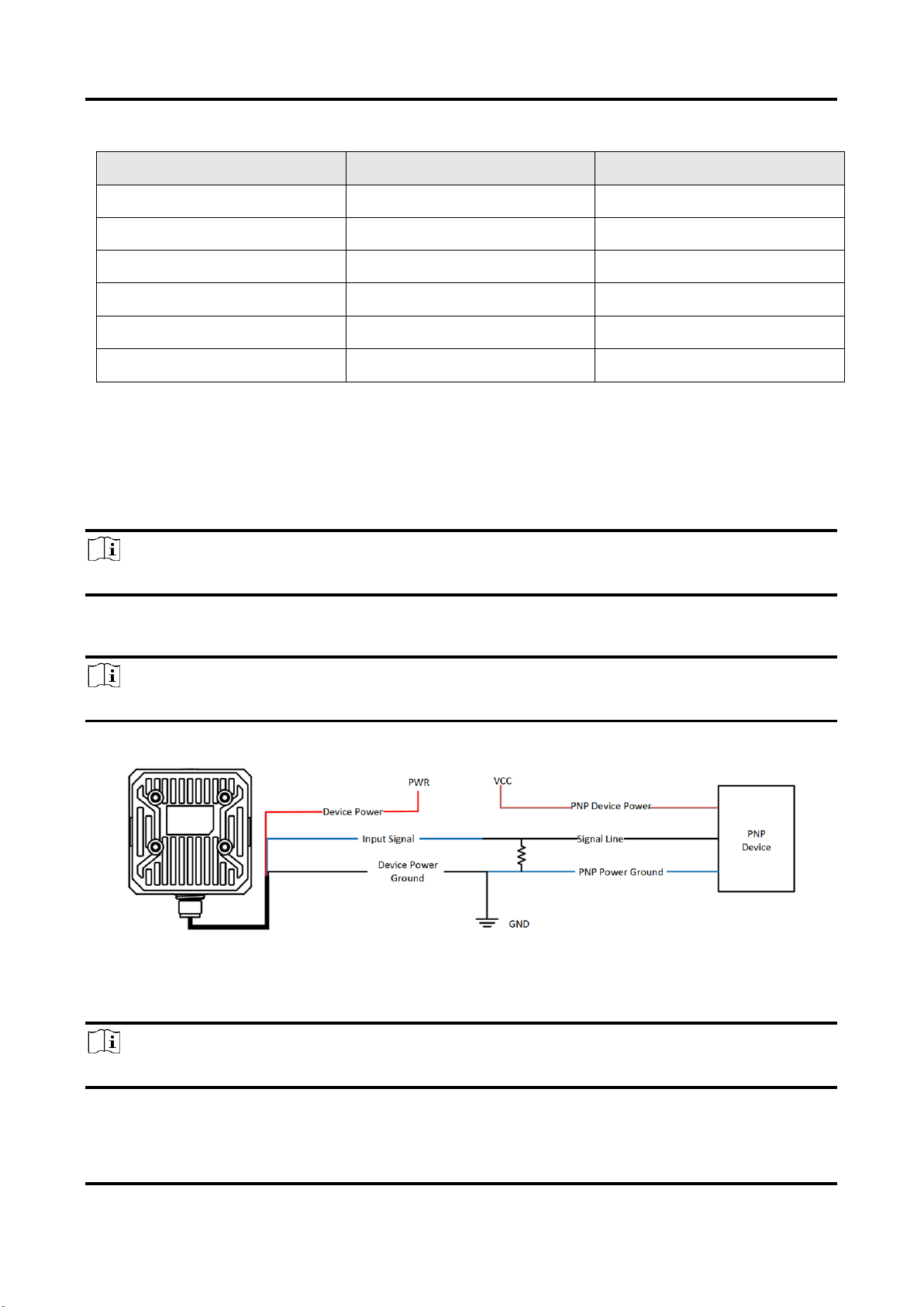
4.3 Input Wiring
The device can receive external input signal via I/O interface, and here we take one line as an
example to introduce input signal wiring.
Note
Input signal wiring may differ with different types of external devices.
PNP Device
Note
It is recommended to use 1 KΩ pull-down resistor.
Figure 4-6 Input Signal Connecting to PNP Device
NPN Device
Note
If the VCC of NPN device is 12 VDC or 24 VDC, and it is recommended to use 1 KΩ pull-up resistor.
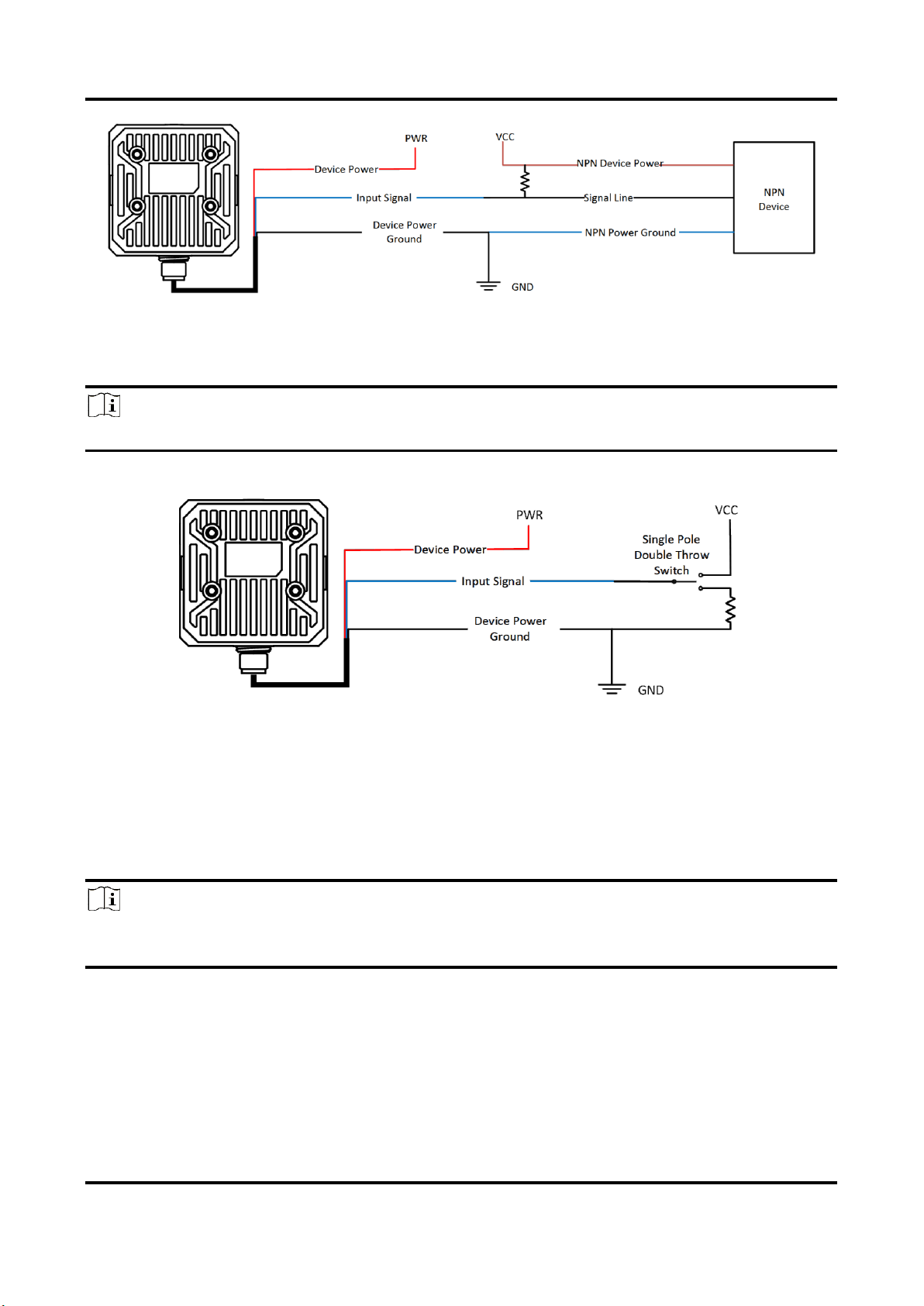
SC2000 Series Vision Sensor User Manual
10
Figure 4-7 Input Signal Connecting to NPN Device
Switch
Note
It is recommended to use 1 KΩ pull-down resistor.
Figure 4-8 Input Signal Connecting to a Switch
4.4 Output Wiring
The device can output signal to external device via I/O interface, and here we take one line as an
example to introduce output signal wiring.
Note
●Output signal wiring may differ with different types of external devices.
●You can set device output signal as NPN or PNP via web.
When the device output signal is PNP, it is recommended to use 1 KΩ pull-down resistor if NPN
device is connected.
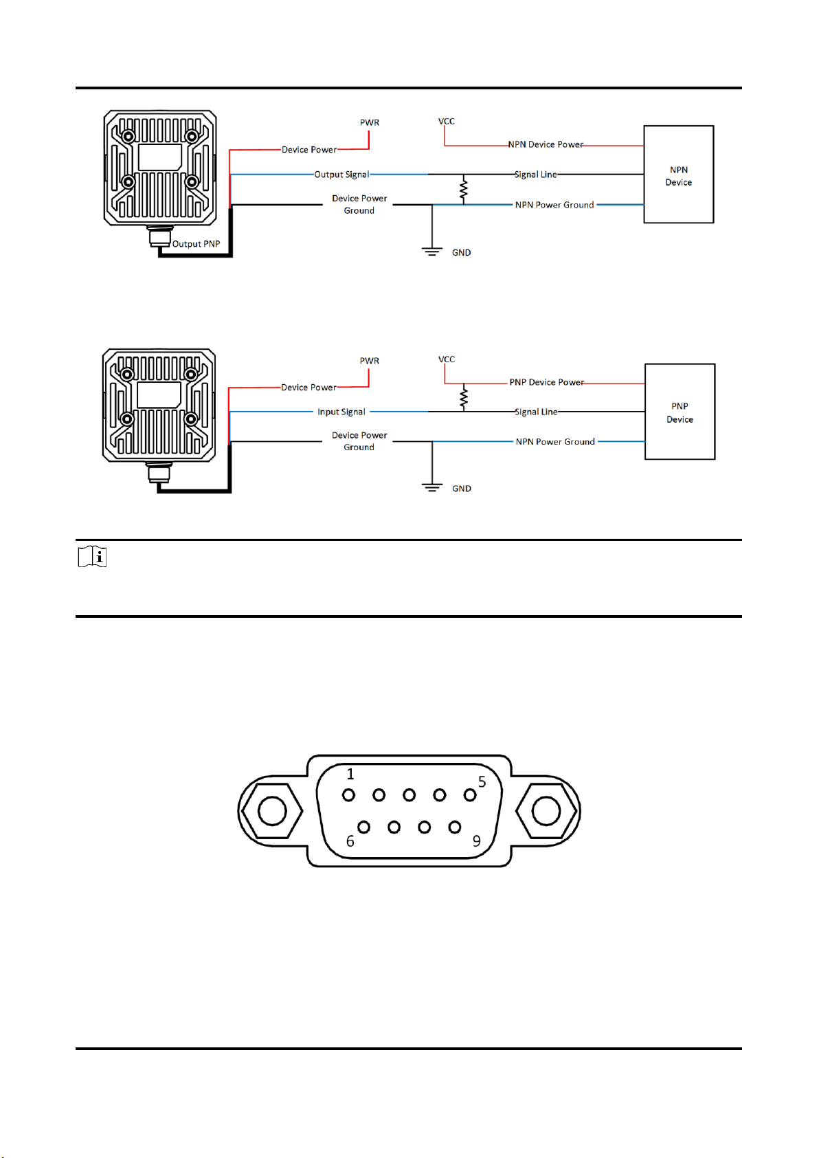
SC2000 Series Vision Sensor User Manual
11
Figure 4-9 Device Outputs PNP Signal
When the device output signal is NPN, it is recommended to use 1 KΩ pull-up resistor if PNP device
is connected.
Figure 4-10 Device Outputs NPN Signal
Note
When the device's output signal is set as NPN, the voltage of VCC should not higher than that of
PWR. Otherwise, the device's output signal may have exception.
4.5 RS-232 Serial Port
The 9-pin male connector and 25-pin male connector are commonly used serial ports, as shown
below. You can refer to the table below for the specific pin name and function.
Figure 4-11 9-Pin Male Connector
Other manuals for SC2000 Series
1
Table of contents
Other HikRobot Accessories manuals


Popular Accessories manuals by other brands

Dorner
Dorner AquaPruf 7400 Ultimate CE Series Installation, Maintenance, and Parts Manual

Hytronik
Hytronik HC005S/IR Installation and instruction manual

Star
Star ECONO EC-CCY Operation manual

Pil Sensoren
Pil Sensoren P41-80-I-CM12 manual

Baumer
Baumer UNAM 18P6903/S14 manual

Dynafit
Dynafit Speed Superlite User instructions

TRENDnet
TRENDnet TE100-SFXM Specifications

Geoquip
Geoquip GeoZone A installation manual

brel-motors
brel-motors DC-1187 manual

Votronic
Votronic Tank Sensor FL Installation and operating manual

PCB Piezotronics
PCB Piezotronics 426A11 Installation and operating manual

Iget
Iget SECURITY M3P10 installation manual


