Star ECONO EC-CCY User manual

ECONO CONVEYER
EC-CCY
OPERATION MANUAL

INTRODUCTION
INTRODUCTION
Thank you for purchasing the Star conveyer “ECONO CONVEYER”.
This operation manual describes the conveyer’s functions, hot to operate it, and the precautions
necessary when using it. Please read this manual thoroughly in order to understand the features
of this conveyer better and use it more efficiently.
Features
● Compact structure because of aluminum frame and resin belt used.
● Can be interlocked with external signals such as your unloader, making it possible to have
intermittent operations and change the tact time for moldings with ease.
● Can be used as a service platform for finishing work because of flat belt surface used.

CONTENTS
CONTENTS
1. SAFETY-RELATED INFORMATION
1-1. Safety-Precaution Indications ··········································· 1
1-2. Safety Precautions ····················································· 2
1-3. Caution plates ························································· 7
1-4. Mechanical Specifications ················································ 8
2. FEATURES AND THEIR LOCATIONS
2-1. General Structure ···················································· 9
2-2. Control Box (Operation Panel) ··········································· 11
3. MECHANICALADJUSTMENTS
・Height adjustment ······················································ 12
・Belt tension adjustment ·················································· 12
・What to do after adjustment ·············································· 13
・Maintenance and inspection ·············································· 13
4. PARTS LIST ························································ 15
5. WARRANTYAND AFTER-SALE SERVICE ······················· 16
6. ELECTRIC CIRCUIT DIAGRAM ···································· 17
7. OVERALL DIAGRAM ················································ 18
-1-
1. SAFET
Y
-RELATED INFORMATION
1. SAFETY-RELATED INFORMATION
1-1. Safety-Precaution Indications
■Danger Level Symbols
The safety precautions in this manual are classified into the following three levels.
DANGER Failure to follow this safety precaution may result in great
physical danger to the operator, or even death.
WARNING Failure to follow this safety precaution may result in great
physical danger to the operator, or severe damage to the
equipment.
CAUTION Failure to follow this safety precaution may result in injury
to the operator, or damage to the equipment.
■About Important Points
Important points on handling are indicated with in the manual.

-2-
1. SAFET
Y
-RELATED INFORMATION
1-2. Safety Precautions
DANGER
PROHIBITING WORKER TO RIDE ON CONVEYER
Never attempt to ride on the conveyer. If the worker rides on the conveyer, it may cause
the risk of making the conveyer unstable and so fall down, getting the worker injured.
DO NOT PERFORM MAINTENANCE WHILE CONVEYER
IS RUNNING!
Never attempt to service or perform maintenance on the conveyer while it is running.
Before carrying out maintenance, be sure to shut down the machinery as follows: (1) Shut
down the air supply. (2) Switch off the POWER switch in the control box. (3) Cut the
power breaker.
WARNING
Wear appropriate work clothes.
Do not wear bulky clothing and accessories when working at the conveyer, as these may
be caught in the machinery, getting the worker seriously injured.
Do not attempt to modify the conveyer.
Do not redesign, rebuild, or otherwise modify the conveyer. The manufacturer cannot be
responsible for accidents or damage caused by modified equipment.
Be sure to ground the conveyer.
Use a No.3 ground setup to help reduce the risk of electric shock at installation. Also,
after moving the conveyer to another place or performing periodic inspection, make sure
that the specified ground setup has been done.
-3-
1. SAFET
Y
-RELATED INFORMATION
Use a non-fuse circuit breaker.
To avoid the risk of fire due to overcurrent, include a non-fuse circuit breaker in the
wiring leading to the power source.
Do not open the cover on the power box.
High voltages are present within the power box. Opening the cover may lead to serious
electric shock.
Do not remove the chain cover for operation.
Operating the conveyer with the chain cover removed may cause the risk of getting the
worker caught or pinched in the machinery.
Do not touch the conveyer belt while it is running.
Never put your hands inside the conveyer belt while it is moving. Doing so may cause the
risk of getting your hands caught or pinched in the conveyer driving rollers.
Shut down operation during periods of frequent power outage.
The machinery should be shut down during times when power supply is frequently going
off due to thunderstorm or other such external event. Operating with an irregular power
supply may lead to equipment damage. If you cannot locate the cause of failure, please
contact the engineering service personnel of our sales office.
CAUTION
Confirm mutual safety in the case of cooperated work.
When two or more persons jointly work together, be sure to clarify who is responsible and
confirm safety by pointing the finger to all safety confirmation places and saying “O.K” if
safe before getting operation started, in order to avoid accidents due to miss-operation or
safety confirmation failure at manual adjustment.
-4-
1. SAFET
Y
-RELATED INFORMATION
Secure adequate maintenance space.
For safe operation, please leave at least 1 meter of maintenance space (with empty floor)
around the circumference of the conveyer.
Work under bright illumination.
To ensure that work is done safety in setting the conveyer and performing service or
maintenance, be sure to work under bright illumination.
Carry out daily maintenance inspections.
Check machinery daily to make sure it is in safe operating condition. Contact STAR
SEIKI in the event of problem.
Stop working in the event of breakdown or other problems.
If you think that the conveyer is abnormal or malfunctioned, do not keep working based
on your own thought. Simply stop operating it. Be sure to get operation started on the
basis of appropriated instructions from our engineering service personnel.
Never touch the switches with wet or dirty hands.
Doing so may cause the risk of not only getting the conveyer malfunctioned but also
accidents due to electric shock.
Stop all devices linked to the conveyer during operation.
Before carrying out inspection, repair, adjustment, cleaning or lubrication work in the
conveyer’s moving range, be sure to shut down not only the conveyer itself but also all
devices linked to is, such as your molding machine, etc. A failure to do this may cause the
risk of getting the worker seriously injured due to unexpected drive.

-5-
1. SAFET
Y
-RELATED INFORMATION
■Kinds of Caution Plates
* Note that some of the caution plates given below are not used on the conveyer.
Caution for high voltage electrical shock
Make sure to cut off the breaker of
controller while maintenance work is
being done. Especially during such work
for inside the box, disconnect connecting
cable with molding machine and cut off
primary power supply of the factory.
This label can be found at the locations
(terminal block, etc.) where special
attention is required in the range of high
voltage warning.
Caution for danger of enfolding
To work in moving zone for maintenance
or other purposes, do not touch carelessly
with such parts as motor, rotary axis, gear,
pulley, belt which have danger of
enfolding you. Cut off power supply and
air pressure to work.

-6-
1. SAFET
Y
-RELATED INFORMATION
● Caution for static electricity
The conveyor belt or the product on the
conveyor may be charged by static
electricity. You may be shocked by electric
when approaching.
.
The conveyor belt
may be charged by
static electricity.
CAUTION
-7-
1. SAFET
Y
-RELATED INFORMATION
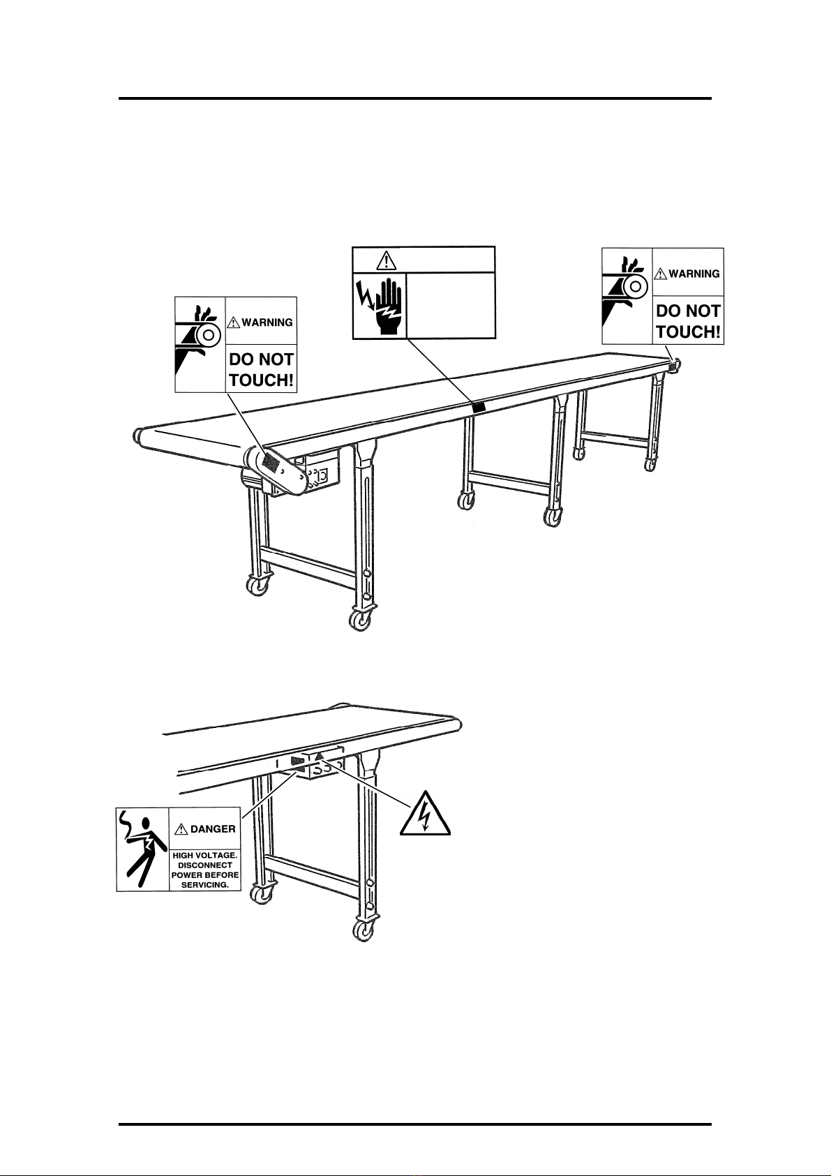
1-3. Caution plates
The following diagram shows the location and content of caution plates affixed to the conveyer.
■Example of caution plates disposition
CAUTION
The conveyor belt
may be charged by
static electricity.

-8-
1. SAFET
Y
-RELATED INFORMATION
1-4. Specifications
Model
EC****-* CCY
Control box CC-4BⅢtype
Belt width 3…300 mm
4…400 mm
5…500 mm
Overall length 4000…4000 mm
5000…5000 mm
Height m/m 900~1300 Free adjustment
Working electric power AC200V 40W
Speed 1~3 m/min (60HZ)
Maximum transport weight
(horizontal position)[kg] 25(15 When option is mounted)
Total weight [kg] See accompanying table.
Optional specifications 1002-02 feet + variable speed specifications
(1~7.5 m/min 60HZ)
●Overall weight (Kg)
Belt width
Overall length 3CCY 4CCY 5CCY 6CCY
EC2000- 41 44 47 50
EC3000- 47 51 55 58
EC4000- 64 69 74 78
EC5000- 69 75 80 86
-9-
2. FEATURESAND THEIR LOCATIONS
2. FEATURES AND THEIR LOCATIONS
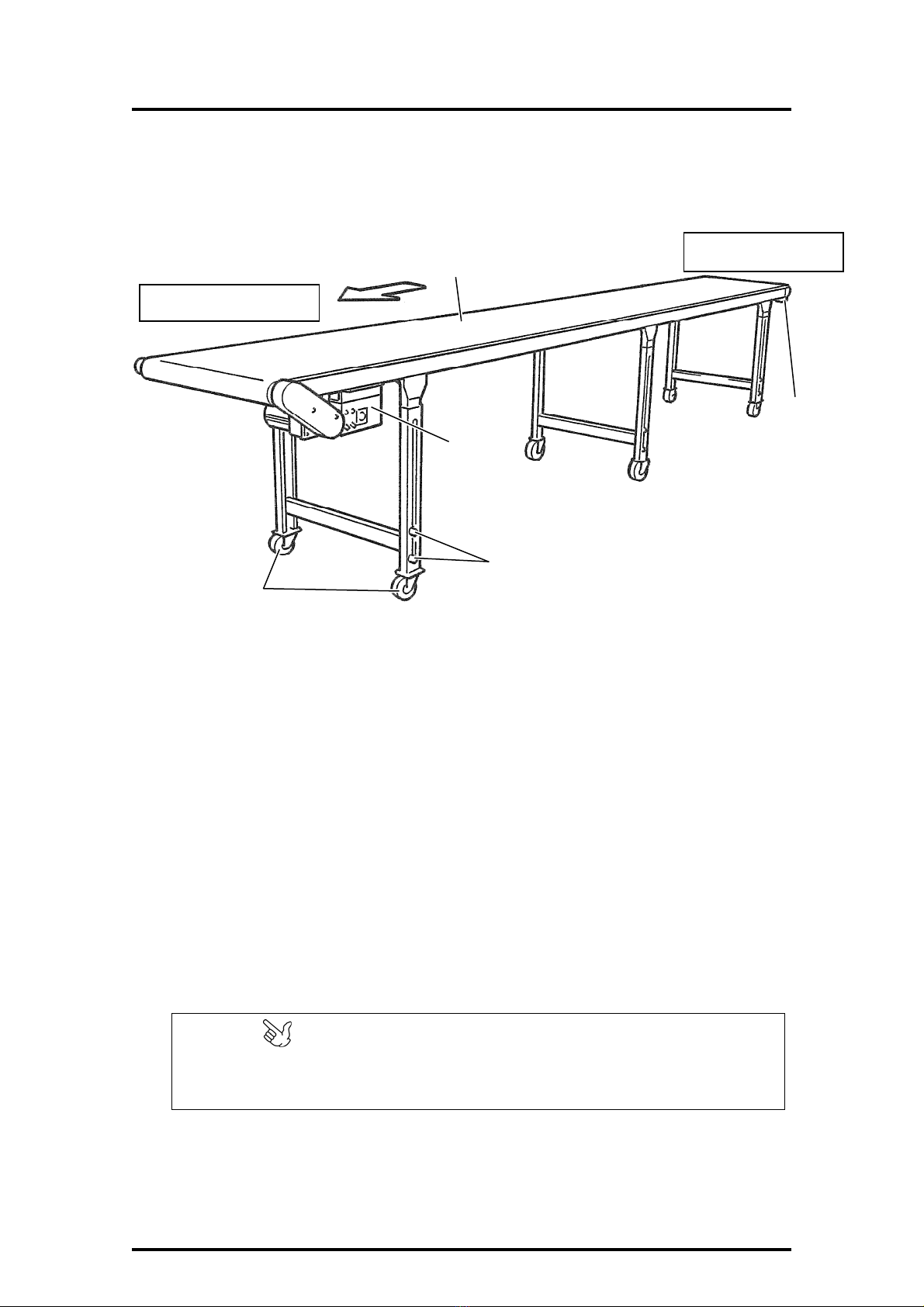
2-1. General Structure
①Conveyer belt
This is a special belt made from synthetic resin.
②Control box
This box is used to set and operate the conveyer drive.
③Caster
These casters are used to move the conveyer. Lock them with the stopper after installing
the conveyer in place.
④Tension adjusting bolt
This bolt is used to adjust the conveyer belt if it is loosened. After adjustment, tighten the
bolt.
⑤Height adjusting/securing bolt
To adjust the height of legs, loosen these securing bolts and adjust the height.
After adjustment, tighten the bolts.
Conveying-out Side
Conveying-in Side
④
②
③
⑤
①
POINT
Do not tense the belt too taut.
Adjust the bolts on both sides uniformly.
-10-
2. FEATURESAND THEIR LOCATIONS
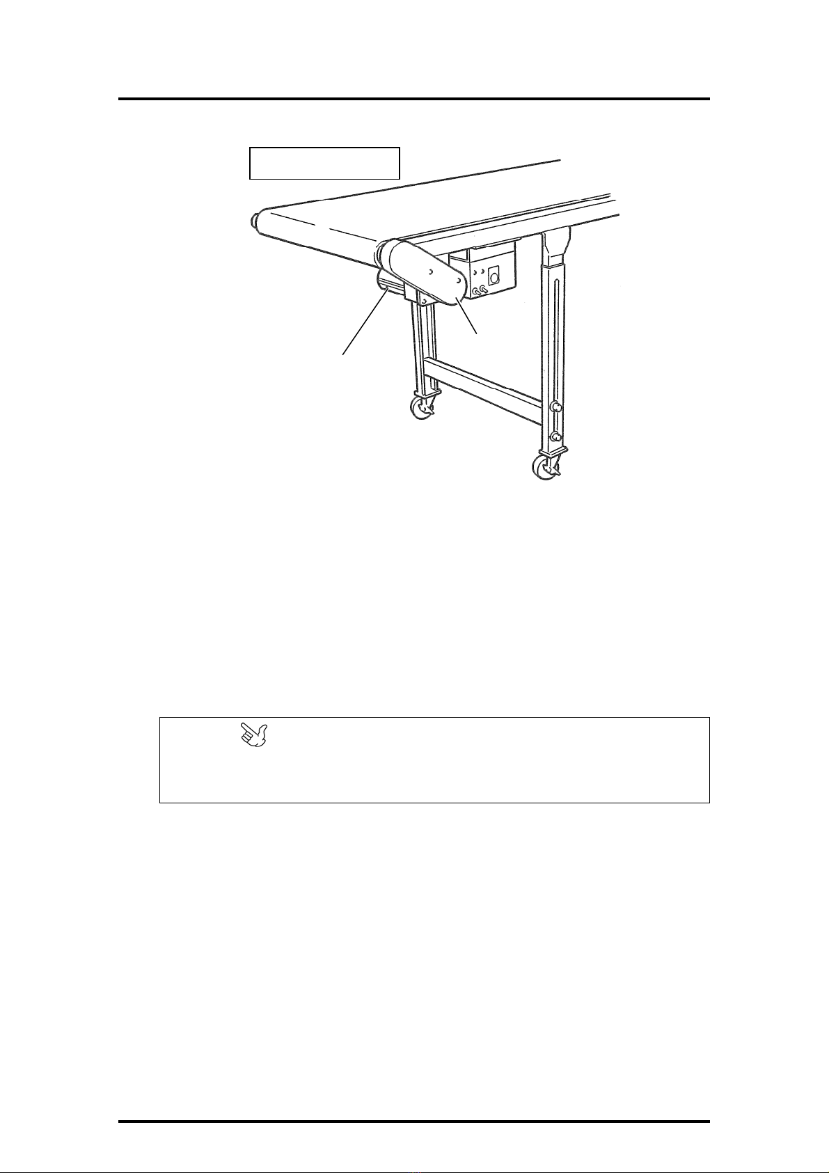
⑥Motor reducer
This is the source of powering up the conveyer. The speed is 1 to 3m per minute (60HZ)
(standard type).
⑦Chain cover
To adjust, maintain or inspect the chain sprocket, remove this cover.
Conve
y
in
g
-out Side
⑦
⑥
POINT
If the conveyer needs to be reversed in rotation, please contact the engineering
service personnel of our sales office.
-11-
2. FEATURESAND THEIR LOCATIONS
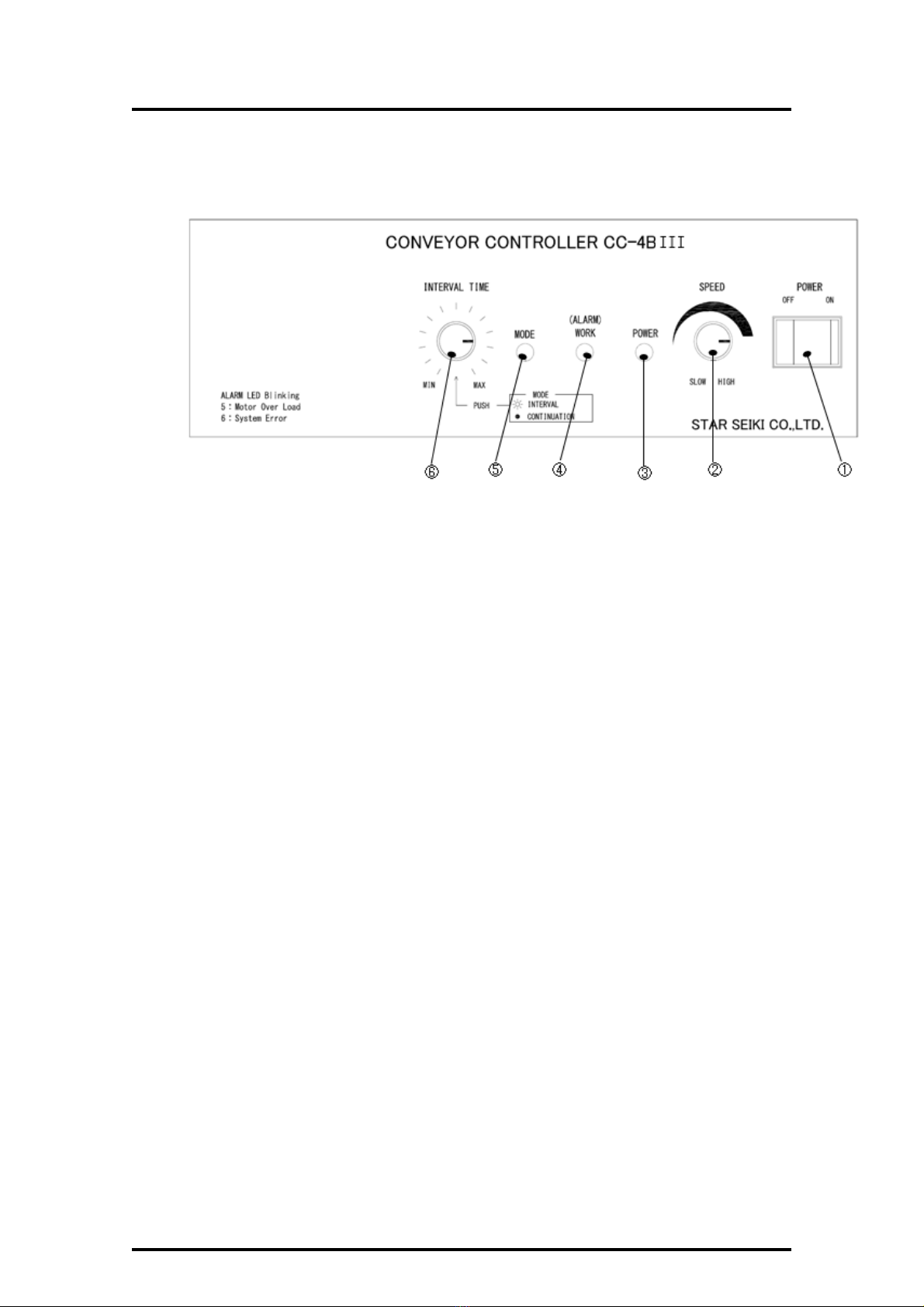
2-2. Control Box (Operation Panel)
●Standard type (CC-4BⅢ)
①Power Switch
Turn on/off the power of conveyor
②Speed Setting Switch
This switch is used to set the speed of product delivery.
Setting range: 1~3m/min
Note: this speed is measured at a frequency of 60Hz.
③Power LED
This LED is on when turning on the power.
④Working LED
The green LED is on when conveyor works normally. The green LED flashes when alarming.
⑤Mode LED
This LED is on when conveyor works in interval mode.
⑥Mode Selecting Switch
This switch is used to shift modes (Press)
・INTERVAL……………Conveyor start signal is input from an Unloader. Conveyor works in
the setting time of timer.
・CONTINUATION………The conveyor works continuously.
Product Delivery Timer (Rotate)
After pressing switch No.6 and select interval mode, please rotate the switch No.6 to set
the time interval for the conveyor to deliver products.
Use this knob to set the product feed speed.
Conveyor speed specified range: 0.25 to 3 m/min (1 to 3 Recommended)
Note : The speed is for 60 Hz.

-12-
3. MECHANICALADJUSTMENTS
3. MECHANICAL ADJUSTMENTS
To determine conveyer arrangement, stop the casters and make the following adjustments.
●Height adjustment
Loosen the height adjusting bolts (2 bolts × 4 to 6
places) located on each leg as shown in the illustration
using a hexagon wrench and adjust the conveyer height.
* Note that after adjustment, tighten the bolts.
●Belt tension adjustment
CAUTION
Adjustment should be made only if the conveyer zigzags sideward or only if the conveyer
driving rollers run idle during operation. Otherwise, there is no need to make adjustment.
Adjust the belt tension using the tension adjusting
bolts at both ends of conveying “IN” side if
necessary.
POINT
Do not tense the belt too taut.
Tighten the bolts on both side uniformly for
adjustment.
After adjustment, tighten the securing nut.
Tightening
Loosening
Tension
adjusting bolt
Securing nut
Securing
Releasing

-13-
3. MECHANICALADJUSTMENTS
●What to do after adjustment …
① Wire the power supply and conveyer start signals.
DANGER
・ Before wiring, shut down the supply-or primary-side power supply.
・ For how to wire conveyer start signals (SG1 and SG2), see the instruction manual for
the control box of your unloader. Also, to input conveyer start signals from other than
the unloaders by STAR SEIKI, please contact the engineering service personnel of
our sales office before using, because incorrect connection procedure may cause the
risk of damaging the electric of the conveyer.
Before plugging in or out the metal connectors, shut down the supply. A failure to do this
may cause the risk of accidents due to electric shock.
●Standard type
WARNING

-14-
3. MECHANICALADJUSTMENTS
●Maintenance and inspection
Remove the chain cover once every 6 months and
apply grease to the chain using brush.
After maintenance or inspection,
return the chain cover in place. A
failure to do this may cause the risk of
getting you caught or pinched in the
chain.
CAUTION

-15-
4. PARTS LIST
4. PARTS LIST
Part Name Type Manufacture Qty Code No.
Motor M91X40GV4Y Panasonic 1 122616
Gear head MX9G90B Panasonic 1 122615
Gear head
(0P 1~7.5m/min)MX9G36B Panasonic 1 122614
Conveyer belt SL-F1502 ****-*** Bando 1

-16-
5. WARRANTYANDAFTER-SALE SERVICE
5. WARRANTY AND AFTER-SALE SERVICE
For information about repairs and other service, refer to the nearest STAR SEIKI business
office.
■Warranty
1. The term of the warranty specified by the contact shall begin upon purchaser’s approval of
the delivered machine. In principle, the term of warranty shall be six (6) months.
2. Breakdowns that occur within the term of warranty period shall be repaired free of charge,
with the exceptions noted immediately below.
3. The following are not covered by the warranty.
・Breakdown caused by inadequate maintenance or inspection.
・Damage caused by improper handling of the machine.
・Damage caused by fire or natural disaster (act of God).
・Damage related to expendable components (chucking parts, etc.)
・Damage caused by modification or attempted repair carried out by user. (Refer to Section
1-5 for machine specifications.)
-17-
6. ELECTRIC CIRCUIT DIAGRAM
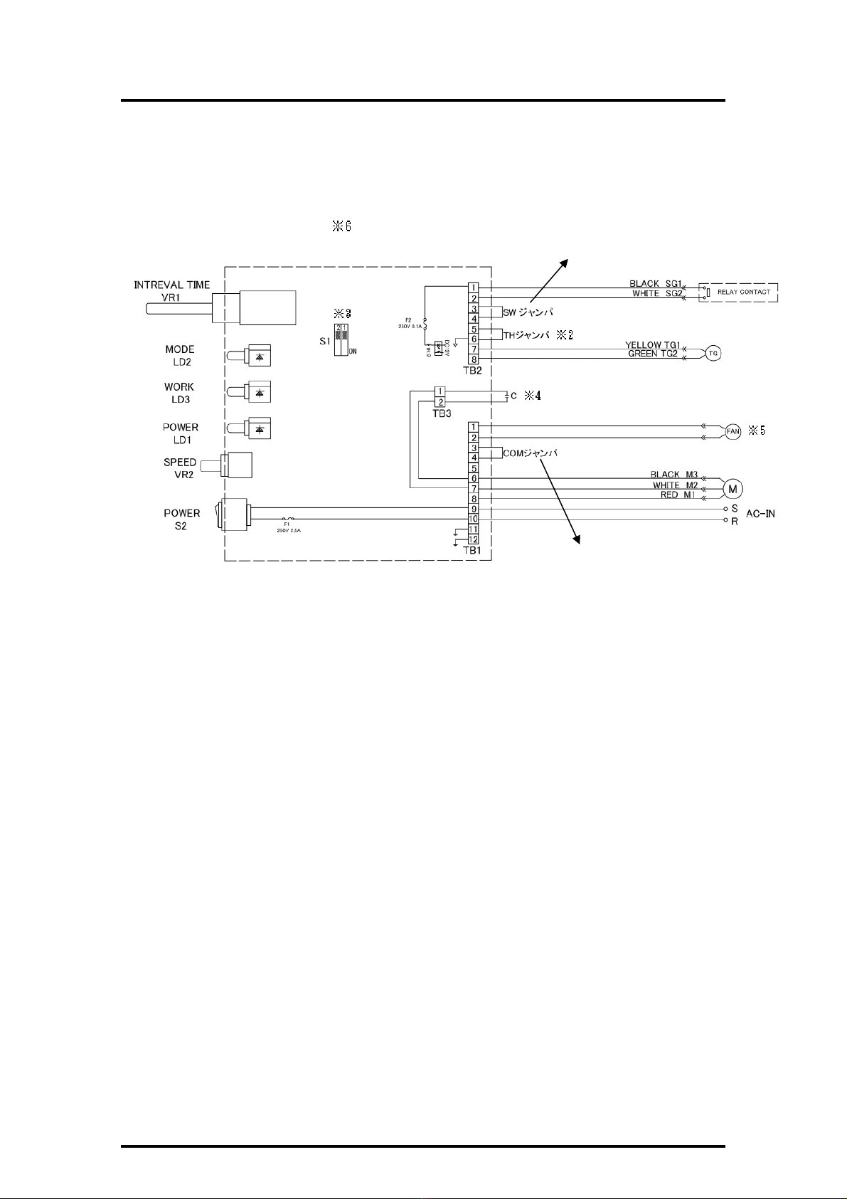
6. ELECTRIC CIRCUIT DIAGRAM
●Econo Conveyer Electric Circuit Diagram (Standard Specifications)
AC200V specifications
※1. Usage method of SW terminal
Under Intermittent action mode, if want to control the conveyor manually, please use SW terminal.
Please use B connection switch.
※
2 Temperature fuse input terminal
SEC conveyor can not use.
※
3 Time selection
S1-2:OFF According to the setting time of Interval Time(VR1)to perform the action.(Standard
Mode)
S1-2:ON Interval Time(VR1)is invalid, SG1 2 is ON, execute the action.
Unloader need to control the time of the action, please use S1-2 ON
※
4 The capacity of TB3 capacitor(The accessory of the Motor)
100V : 12uF/250V
115V : 10uF/250V
200V : 3uF/450V
220/230V : 2.5uF/450V
※
5 If use 90W (Or above 90W) type of motor, need to connect the fan.
The supply voltage of the fan is the same as the output voltage of the conveyer。
※
6 The input voltage of the Board is AC100V or AC200V. Do not need power supply shift switch。
Due to the different voltage, the connection of the motor, TB3 capacitor etc. are also different.
Please pay attention to it.
※1 External switch OPEN: Permanent action
External switch Close: Intermittent action
Rotation direction shift terminal
(COM,CW,CCW)
SEC conveyor can not use
Please do not alter the COM Jumper
Table of contents
Other Star Accessories manuals


Popular Accessories manuals by other brands


Wavion
Wavion WBSn-2400 quick start guide

Endress+Hauser
Endress+Hauser Deltabar S PMD70 Exchange instruction

Bühler technologies
Bühler technologies easyMont IO-Link Pressotronik PT77 Brief instructions

Betta
Betta 6000 installation guide

LEGRAND
LEGRAND Wattstopper FSP-211B installation instructions

Paramount Fitness
Paramount Fitness Ultra UV2 Replacement manual

Interlogix
Interlogix HDX-135 installation instructions

Continental Refrigerator
Continental Refrigerator CBC37 Specifications

Pentair
Pentair PENTEK VFD-WS owner's manual

PCB Piezotronics
PCB Piezotronics IMI SENSORS 080A130 Installation and operating manual

JoeCo
JoeCo Cello user manual

Leviton
Leviton OSSMD-FT install guide