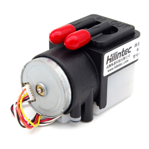
Hilintec D08 Series User manual

D08 Flo w Con t ro l Vacu u m Pum p and
Com p r ess o r Ser ies
Use r Gui de
Issue
1.0
Date
2021-10

D08 Flow Cont rol Va c u u m Pump an d Comp r essor Ser ies User Guide
Copyright © Chengdu Hilin Technology Co. Ltd.
Copyright © Chengdu Hilin Technology Co., Ltd. 2020. All rights reserved.
No part of this d o cu m ent m a y be repr o d u c e d or tran s m itte d in any fo r m or by an y m eans
wit hout prior writ ten consen t of Chen g du Hil i n Tech n o l o g y Co . , Ltd .
Trademarks and Permissions
is a tra d e mark of Che n g d u Hili n T echno l o g y Co., L t d .
All ot her tr a d e m a r ks an d tr ade na m e s m enti o n e d in this docu m e n t a r e the pr o p e r t y of
the i r r e s p e c t i v e holde r s .
Notice
The pur ch a s e d pro d u ct s, serv i ce s and featu r es are stipul a t e d by the cont r a c t made
bet w een Che n gdu H i l i n Tec h n o l o g y C o . , Lt d . an d t he cu s t ome r . Al l o r pa r t o f the pr o d u c t s ,
ser v i c e s and fea t ures des cr ibed in th i s docu m ent ma y not b e wit h in t h e pu r c h a s e scop e
or the us a g e sco p e . U n le s s oth e r w ise sp e ci f i e d in th e c on t r a c t , al l s t a t e m e nt s ,
inf o r m atio n , and r e co m men d a t i o n s i n th i s do c u m e nt a r e prov i d e d " A S I S " w i thou t
war rant i e s , gu a r ante e s or rep r esen t a t ions o f a n y k ind, e it her e x pre s s or im p lied .
The infor m atio n in this docum ent is subj e c t to cha n g e wit hout n otice . Eve r y eff o r t has
been m a d e i n t h e p r e p a r atio n o f t h i s docume n t t o e n s u r e accur acy of th e c o n t e n t s, but
all s t a t e m e n t s , i n f o r m a t i o n , a n d reco m m e n d a t i o n s in thi s d o cu m e n t do no t c o n s t it ute a
war rant y of any k ind, ex pre s s o r i m p l i e d .
Chengdu Hilin Technology Co., Ltd.
Address:
No.3663 Section 2 Muhua Road
Shuangliu District
Chengdu Sichuan China 610000
Website:
http://www.mini-pump.com
Tel:
+86-28-62567958

D08 Flow Cont rol Va c u u m P u mp and Co m pres s or Se r ies User Gui d e
Copyright © Chengdu Hilin Technology Co., Ltd.
1
About This Document
Purpose
This document is a description of the D08 flow control vacuum
pump and compressor products in testing period, which is used to
guide relevant technical personnel to initially understand the
characteristics of the product.
Intended Audience
This document is intended for technical personnel. You should have
a good understanding of your product and have a clear concept of
the relevant parameters, specifications, and other information of the
applications of the micro pump.
Keyword
Compact size,wide voltage power supply, stable flow rate,related
parameters, wiring instructions

D08 Flow Cont rol Va c u u m P u mp and Co m pres s or Se r ies User Gui d e
Copyright © Chengdu Hilin Technology Co., Ltd.
2
Change History
The change history accumulates each update of this document. The
latest version of the document contains all the previous updates.
Issue
Date
Product
Version
Issuer
Modification
01
2021-8
1.0
GZM
First official release.
01
2021-10
1.0
GZM
Added BDC parameters

D08 Flow Cont rol Va c u u m P u mp and Co m pres s or Se r ies User Gui d e
Copyright © Chengdu Hilin Technology Co., Ltd.
3
Contents
Ab ou t T hi s Do c u m e n t
..............................................................................................1
Ch an ge H is to r y
......................................................................................................... 2
Co n t e n t s
......................................................................................................................3
1Ch a r ac t e r i s t i c s
....................................................................................................... 1
1.1 Compact Size..................................................................................................................................... 1
1.2 Multiple motor options.......................................................................................................................1
1.3 High vacuum, Big pressure................................................................................................................1
1.4 Industrial-grade reliability..................................................................................................................2
2Fu n c t i o n s
.................................................................................................................2
2.1 Speed Control Function..................................................................................................................... 2
2.2 Modular hose connector options........................................................................................................ 2
3Te ch n ic a l Sp ec i f i ca t i o ns
.................................................................................... 3
3.1 Performance Specifications................................................................................................................3
3.2 Configuration Options........................................................................................................................4
3.3 Reliability Parameters........................................................................................................................ 5
3.4 Versions Description..........................................................................................................................6
3.5 List of Models Combination for Sale.................................................................................................7
3.6 Pump material..................................................................................................................................... 7
3.7 Flow Rate Curve................................................................................................................................ 7
3.8 Starting Current..................................................................................................................................8
4Pr o d u ct Mo d el D e s c r i p t i o n
................................................................................9
4.1 Brief Description of Model Naming.................................................................................................. 9
5El ec t r ic a l Co n ne ct i o n
.........................................................................................10
5.1 Definition of Signals(Equipped with BDC motor).......................................................................... 10

D08 Flow Cont rol Va c u u m P u mp and Co m pres s or Se r ies User Gui d e
Copyright © Chengdu Hilin Technology Co., Ltd.
4
5.2 Logic Wiring Diagram(Equipped with BDC motor)......................................................................... 9
5.3 Definition of Signals(Equipped with BLDC motor)..........................................................................9
5.4 Logic Wiring Diagram(Equipped with BLDC motor).......................................................................9
6Ca ut i on s
.................................................................................................................13
7Di m e n s i o n s
............................................................................................................15
8Ap p e ar a n c e
...........................................................................................................16

D08 Flow Cont rol Va c u u m P u mp and Co m pres s or Se r ies User Gui d e
Copyright © Chengdu Hilin Technology Co., Ltd.
1
1Characteristics
1.1 Compact Size
The overall size of the product(equipped with a brushless motor) is
about 34.5×21×32.5mm; the overall size of the product(equipped
with a brushed motor) is 40 ×17 ×23.5mm; it is suitable for
applications that require a very small space of air pumps.
1.2 Multiple Motor Options
Two choices of brushed and brushless motors are provided to meet
the different needs of costs and service lifetime;
The brushless motor uses 12V DC power supply; the brushed motor
uses 3-5V DC power supply.
1.3 High Vacuum, Big Pressure
Under the premise of extremely compact size, it can achieve
vacuum degree -49kPa and maximum positive pressure 88kPa;

D08 Flow Cont rol Va c u u m P u mp and Co m pres s or Se r ies User Gui d e
Copyright © Chengdu Hilin Technology Co., Ltd.
2
1.4 Industrial-grade Reliability
Whether pumps equipped with brushed motors or brushless
motors,which have passed rigorous life tests and promise to meet
industrial-grade reliability requirements under test conditions.

D08 Flow Cont rol Va c u u m P u mp and Co m pres s or Se r ies User Gui d e
Copyright © Chengdu Hilin Technology Co., Ltd.
3
2Functions
2.1 Speed Control Function
For brushed motor version, The flow rate of the pump can be
changed by adjusting the motor speed and changing the input
voltage , For brushless motor version,The flow rate of the pump can
be changed by adjusting the motor speed through PWM signal.
2.2 Modular Hose Connector Options
Under the premise of a small volume, a replaceable connector is
available, which can be equipped with copper or stainless steel hose
connector and M3 internal thread connectors.

D08 Flow Cont rol Va c u u m P u mp and Co m pres s or Se r ies User Gui d e
Copyright © Chengdu Hilin Technology Co., Ltd.
1
3Technical Specifications
3.1 Performance Specifications
(Standard atmospheric pressure 101kpa)
M o de l
V ol t a g e
(V D C )
M a x .
L oa d
Cu r r e nt
(m A )
M a x F l o w r a t e
(L /m i n)
M a x .
V a c u u m
( - k P a )
M a x . P r e s s u r e
( k P a )
P e ak
F l ow
A v e r a g e
F l ow
Material Option A
Pump Head:Aluminum Alloy,Diaphragm/Valves:EPDM, Motor: BDC
D08L-53-0610
5
≤210
≥110
≥95
≥49
≥88
Material Option B
Pump Head:Aluminum Alloy,Diaphragm/Valves:EPDM, Motor: BLDC
D08L-23-0600
12
≤65
≥210
≥175
≥46
≥75
N ot e :
1.O p e r a t i n g volt a g e 、 i n put vo l t a g e ch a n g e s w ill af f ect th e l o a d cu r r ent
2.U n l e s s oth e r wis e s p e c i f i e d , t he tec h n i c a l pa r amet e r s are me a s u r ed und e r
the con d it i o n s o f te m p e r a t u r e 20℃ a n d st a n d a r d a t m o s ph e r i c p r es s u r e o f
101 k P a .
3. The p a r a m eter s i n t h e t a b l e are me a s u r ed at th e ma x imu m s p e e d of the
mot o r . Wh en the mot or s p e e d ch a n g e s , the pr essu r e /v acuu m l e v el is
basi c a l l y un chan g e d .
4. The p e ak f l ow rat e in the t ab l e re f e r s t o t h e f l o w v al u e m easu r e d w i t h a
rot a m e t er, an d t h e a v e r age flo w rat e i s m e a s u r e d w ith a so a p f i l m
flow -me t e r .

D08 Flow Cont rol Va c u u m P u mp and Co m pres s or Se r ies User Gui d e
Copyright © Chengdu Hilin Technology Co., Ltd.
2
3.2 Configuration Options
Material
option
pump head
Reinforced nylon
diaphragm
EPDM
one-way valve
EPDM
motor
BLDC
BDC
Connector
Option
Connector type
default copper hose
connector
304 stainless steel hose
connector

D08 Flow Cont rol Va c u u m P u mp and Co m pres s or Se r ies User Gui d e
Copyright © Chengdu Hilin Technology Co., Ltd.
3
3.3 Reliability Parameters
M o de l s
D 0 8 L e q u i p p e d w i t h B L D C m o t o r
V e r s i on s
S i m p l i f i e d
S t a n d a r d
P r e m i u m
Fully Loaded Lifetime
(hrs)
12000
(Estimated lifetime)
Unloaded Lifetime
(hrs)
18000
Motor Lifetime(hrs)
20000
Lifetime test
instructions:
Full-load life test conditions: block the exhaust port of the pump, and the
suction port is directly connected to the atmosphere, so that the pump
can operate continuously without stopping for 24 hours under the
maximum vacuum condition;
No-load life test conditions :The pump suction port and exhaust hole
are directly open to the atmosphere, so that the pump works under
normal pressure for 24 hours without stopping and continuous operation;
Motor life test conditions: under good ventilation and heat dissipation
conditions, the motor does not carry a load for 24 hours without stopping
Continuous operation;
Environmental conditions for life test: In a clean, non-corrosive
laboratory, the ambient temperature is 5~33℃fluctuates with the
climate, and the relative humidity of the environment is 50%~85%,
fluctuates with the climate;
The source of the experimental data is from Hailin Technology Aging
and life laboratory and supplier laboratory

D08 Flow Cont rol Va c u u m P u mp and Co m pres s or Se r ies User Gui d e
Copyright © Chengdu Hilin Technology Co., Ltd.
4
Working
Conditions
Environment
Permissible ambient temperature range of the simplified version products is 0℃~
40℃, and the permissible ambient temperature of the standard and premium
versions is 0℃~50℃. The permissible relative humidity of all pumps in this series
is ≤90%, no condensation.The pump should not be exposed to the sun, and should
work in a clean and ventilated environment.
Medium
Permissible gaseous media temperature range is 0℃~50℃. The medium is allowed
to contain water vapor, but cannot contain particles or oil mist.
Load
The inlet/outlet can be operated at full load (i.e. completely block the inlet/outlet),
but the applied load cannot exceed the maximum vacuum of the pump; the outlet
must keep unobstructed.
Corrosion
The materials of the wetted parts:nozzle, pump head,diaphragm,one-way valve(See
Configuration Options for component materials),The above materials have a certain
degree of corrosion resistance. Please further judge the resistance to the medium
according to the wetted materials

D08 Flow Cont rol Va c u u m P u mp and Co m pres s or Se r ies User Gui d e
Copyright © Chengdu Hilin Technology Co., Ltd.
5
3.4 Versions Description
Per f or m a n ce
Ver sion
Sim p l i f i e d
Ver sion
Sta n d a r d V e r s i o n
Pre m i u m Ver s i o n
Lif e t i m e
★★
★★★
★★★★
Nois e
★
★★
★★★
Rel i a b i l i t y
★
★★
★★★
Par a m e t er
Cons i s t ency
★
★★
★★★
N ot e : 1 . T h e m o r e ★, t h e b e t t er p er f o r m an ce o f t h i s i t e m .
2 . T h e q u a n t i t y ★ i s f o r r e f e r e n c e o n l y , s o t h a t r ea d e r s c a n u n d e r s t a n d
t h e d i f f e r e n ce s b e t w e e n v e r s i on s .
3.5 List of Models Combination for Sale
Version
Type
Sim p l i f i e d Ver s i o n
Sta n d a r d
Ver sion
Pre mium
Ver sion
D08L
equipped with
BLDC motor
/
/
√
D08L
equipped with
BDC motor
/
/
√
3.6 Pump Materials
The materials of the wetted parts: LY12 aluminum alloy,EPDM
rubber and copper. Please check the tolerance of the medium
according to the wetted material.(For special needs, you can
customize stainless steel head and stainless steel pneumatic
connectors.

D08 Flow Cont rol Va c u u m P u mp and Co m pres s or Se r ies User Gui d e
Copyright © Chengdu Hilin Technology Co., Ltd.
6
3.7 Flow Rate Curve

D08 Flow Cont rol Va c u u m P u mp and Co m pres s or Se r ies User Gui d e
Copyright © Chengdu Hilin Technology Co., Ltd.
7
3.8 Starting Current

D08 Flow Cont rol Va c u u m P u mp and Co m pres s or Se r ies User Gui d e
Copyright © Chengdu Hilin Technology Co., Ltd.
8
4Product Model Description
4.1 Brief Description of Model Naming
This series of products are premium version.
Exa m p l e 1 : D 0 8 L -5 1 J - 0 6 1 0 (D08L pump , 5V vol t a g e , basic si m p l i f i ed ver s i o n ,
rub b e r m ater i a l : EP DM , pum p head mat e r ial: LY1 2 a l u m i n um al l o y , bru s h e d
mot o r , conn e c t o r t ype: h o s e connec t o r )

D08 Flow Cont rol Va c u u m P u mp and Co m pres s or Se r ies User Gui d e
Copyright © Chengdu Hilin Technology Co., Ltd.
9
5Electrical Connection
The Electrical Connection section introduces how to connect this
product to an external power supply and the wiring instruction of
signal wires. This product is equipped with standard connection
wires at the factory, and the wire definitions are distinguished by
colors.
5.1 Definition of Signals(D08 Equipped with BDC Motor)
There are 5 motor wires for this product. The wiring and usage instructions are as
follows.
5.2 Logic Wiring Diagram(D08 Equipped with BDC
Motor)
S . N .
C o l o r
F u n c t i o n
E x p l a n a t i o n
R e m ar k s
1
Black
Negative pole of the
power supply
GND
2
Red
Positive pole of the
power supply
DC5V

D08 Flow Cont rol Va c u u m P u mp and Co m pres s or Se r ies User Gui d e
Copyright © Chengdu Hilin Technology Co., Ltd.
10
5.3 Definition of Signals(D08 Equipped with BLDC Motor)
There are 5 motor wires for this product. The wiring and usage instructions are as
follows.
N o t e : If s p e e d cont r ol a n d s p e e d feed b a c k ar e n o t need e d , t h e r e d w ire sha l l b e
conn e ct e d to t h e posi t i v e pole of th e pow e r supp l y , and the black, whi t e and
ora n g e w ires co n n e c t e d to the nega t ive pole of t he power supp l y ; the yel l o w
wir e shal l b e in s u l a t e d a n d wr a p p e d .
S . N .
C o l o r
F u n c t i o n
E x p l a n a t i o n
R e m ar k s
1
Black
Negative pole of the
power supply
GND
2
Red
Positive pole of the
power supply
DC12V (±10%)
3
Yellow
FG feedback signal
(motor speed feedback
signal, pulse signal), the
motor outputs 6 pulses
per rotation
Output:
4V≤High Level
Low Level≤0.6V
The maximum rated
current of the FG
feedback signal is
3mA.
The internal of the motor is
open-drain, which requires a
pull-up externally. Voltage
DC 5V, resistance 4.7kΩ.
4
White
Pulse Width
Modulation(PWM)
Input:
0V≤VIL≤0.8V
2V≤VIH≤..5V
(15kHz~25kHz)
Use PWM to change the
motor speed and adjust the
flow. PWM input signal
frequency range: 15kHz ~
25kHz. This port cannot be
used to control the start and
stop of the pump.
5
Orange(
or
Gray)
Control the start and
stop of the motor.
Input:
Level Signal:
2V≤Stop≤5V
0V≤Start≤0.8V
This signal line can be used
to control the start and stop
of the pump, especially for
frequent start and stop. If the
pump does not work for a
long time, disconnect the red
power cord.

D08 Flow Cont rol Va c u u m P u mp and Co m pres s or Se r ies User Gui d e
Copyright © Chengdu Hilin Technology Co., Ltd.
11
5.4 Logic Wiring Diagram(D08 Equipped with BLDC
Motor)
If speed control and speed feedback are not needed, the red wire
shall be connected to the positive pole of the power supply, and the
black, white and orange wires connected to the negative pole of the
power supply; the yellow wire shall be insulated and wrapped and
the pump will work at the rated speed.
When you need to use the PWM speed control function, you need to
use a signal source that supports PWM signal output (function
signal generator, MCU, PLC, etc.), connect the signal source output
to the white PWM input cable, and connect the PWM signal source
ground to the ground of the DC power supply and wrap the yellow
wire with insulation.
This manual suits for next models
2
Table of contents
Other Hilintec Water Pump manuals
Popular Water Pump manuals by other brands
Danfoss
Danfoss PAH 25 instructions
ULTIMATE SPEED
ULTIMATE SPEED 12 V UOP 12 C1 Operation and safety notes

Gotec
Gotec eckerle SP32/02-80-M technical information
Atlas Copco
Atlas Copco LWP 2 Safety and operating instructions
PG Drives Technology
PG Drives Technology SK79647-02 Technical manual

JEC Pumps
JEC Pumps JRZL Series operating & maintenance manual
