Hilintec C15 User manual

Copyright © Chengdu Hilin Technology Co., Ltd.
C15 Flow Control Vacuum Pump series
User Guide
Issue
11
Date
2020-06

C15 Flow Control Vacuum Pump series User Guide
Copyright © Chengdu Hilin Technology Co., Ltd.
Copyright © Chengdu Hilin Technology Co., Ltd. 2020. All rights reserved.
No part of this document may be reproduced or transmitted in any form or by any means
without prior written consent of Chengdu Hilin Technology Co., Ltd.
Trademarks and Permissions
is a trademark of Chengdu Hilin Technology Co., Ltd. All other trademarks and
trade names mentioned in this document are the property of their respective holders.
Notice
The purchased products, services and features are stipulated by the contract made
between Chengdu Hilin Technology Co., Ltd. and the customer. All or part of the products,
services and features described in this document may not be within the purchase scope or
the usage scope. Unless otherwise specified in the contract, all statements, information,
and recommendations in this document are provided "AS IS" without warranties,
guarantees or representations of any kind, either express or implied.
The information in this document is subject to change without notice. Every effort has
been made in the preparation of this document to ensure accuracy of the contents, but all
statements, information, and recommendations in this document do not constitute a
warranty of any kind, express or implied.
Chengdu Hilin Technology Co., Ltd.
Address:
No.3663 Section 2 Muhua Road
Shuangliu District
Chengdu Sichuan China 610000
Website:
http://www.hilintec.com
Tel:
+86-28-62567958

C15 Flow Control Vacuum Pump Series User Guide
Copyright © Chengdu Hilin Technology Co., Ltd.
I
About This Document
Purpose
This document is a description of the C15 flow control vacuum
pump series in the test period, which is used to guide the relevant
technical personnel to understand the product characteristics.
Intended Audience
This document is intended for technical personnel. You should have
a good understanding of your product and have a clear concept of
the relevant parameters, specifications, and other information of the
applications of the micro pump.
Keyword
PWM speed control, working status indicator, related parameters,
wiring instructions

C15 Flow Control Vacuum Pump Series User Guide
Copyright © Chengdu Hilin Technology Co., Ltd.
II
Change History
The change history accumulates each update of this document. The
latest version of the document contains all the previous updates.
Issue
Date
Product
Version
Issuer
Modification
01
2018-3
1.0
LT
First official release
02
2018-4
1.0
LT
Determine preliminary
product model and
parameters
03
2018-5
1.0
LT
Define product model, add
circuit signals and
connection instructions
04
2018-10
1.0
LT
Add product images and
model of matching speed
controllers
05
2018-11
1.0
LT
Add description of product
version and speed feedback
06
2019-09
1.0
LYZ
Modify the document
format
07
2019-12
1.0
FB
Update notes in section 3.1
08
2020-02
1.0
FB
Add model description;
update outline drawing
09
2020-03
1.0
FB
Update definition of FG
feedback signal
10
2020-04
1.0
FB
Update some descriptive
terms
11
2020-06
1.0
FB
Update medium description

C15 Flow Control Vacuum Pump Series User Guide
Copyright © Chengdu Hilin Technology Co., Ltd.
III
Contents
About This Document............................................................................................... I
Change History..........................................................................................................II
Contents.................................................................................................................... III
1Product Characteristics........................................................................................1
1.1 Compact Size..................................................................................................................................... 1
1.2 Working Status Indicator....................................................................................................................1
1.3 Brushless Motor................................................................................................................................. 1
1.4 Protections..........................................................................................................................................1
2Special Features.....................................................................................................2
2.1 Speed Control Feature........................................................................................................................2
2.2 Warning Feature................................................................................................................................. 2
3Technical Parameters........................................................................................... 3
3.1 Key Parameters.................................................................................................................................. 3
3.2 Description of Versions......................................................................................................................4
3.3 Life-time Test Conditions.................................................................................................................. 4
3.4 Working Conditions........................................................................................................................... 4
3.5 Materials.............................................................................................................................................5
3.6 Parameter Curve.................................................................................................................................5
4Product Model Description................................................................................. 6
4.1 Brief Description of Model Naming.................................................................................................. 6
This series of pumps are mainly: basic type.............................................................................................. 6
5Electrical Connection............................................................................................7
5.1 Definition of Signals.......................................................................................................................... 7

C15 Flow Control Vacuum Pump Series User Guide
Copyright © Chengdu Hilin Technology Co., Ltd.
IV
5.2 Logical Wiring Diagram.................................................................................................................... 8
6Cautions................................................................................................................. 10
7Dimensions............................................................................................................ 11
8Appearance............................................................................................................12
C15 Flow Control Vacuum Pump Series User Guide
Copyright © Chengdu Hilin Technology Co., Ltd.
1
1Product Characteristics
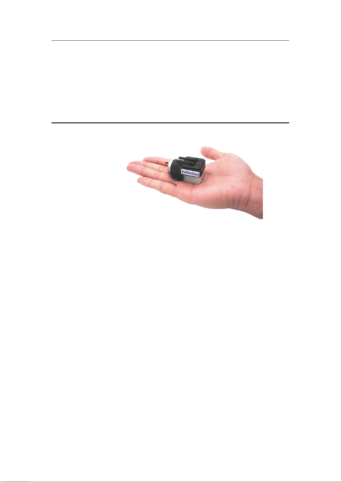
1.1 Compact Size
The product weighs about 50g and the overall size is about
50x29x36mm.
1.2 Working Status Indicator
The bottom case of the pump is made of the light-transmitting
material ABS, which can directly reflect the working status of the
pump through the indicator light.
1.3 Brushless Motor
This model is driven by brushless motors which have the advantages
of long service life, low interference and high reliability.
1.4 Protections
Equipped with overheating protection, overload protection and
reverse connection protection function to prevent accidental damage
to the pump.

C15 Flow Control Vacuum Pump Series User Guide
Copyright © Chengdu Hilin Technology Co., Ltd.
2
2Special Features
2.1 Speed Control Feature
The flow can be changed by adjusting the motor speed of the pump
(by adjusting the PWM duty cycle).
Or you can order from our company a special speed controller for
micro pump (model: TS-G12) to regulate the speed.
2.2 Warning Feature
The color of the indicator light displayed on the transparent bottom
case (as shown in Figure 2-1 and Figure 2-2) can feedback the
working status of the pump:
1. It is normal when the blue light flashes regularly;
2. When the light remains red, it is abnormal, i.e. the motor runs too
low;
3. When the red and blue lights flash alternately, it is abnormal, and
at this time,the motor speed is low and unstable;
4. The indicator light is off when the positive and negative
connections are reversed;
5. When the voltage is out of the working voltage range (3.2V~6V),
the indicator light is off.
Figure 2-1 Normal working status Figure 2-2 Abnormal working status

C15 Flow Control Vacuum Pump Series User Guide
Copyright © Chengdu Hilin Technology Co., Ltd.
3
3Technical Parameters
3.1 Key Parameters
Model
Rated
Voltage
(V DC)
Load
Current
(mA)
Flow(L/min)
Relative
Vacuum
(kpa)
Weight
(g)
Peak
Flow
(L/min)
Average
Flow
(L/min)
C15L
5
≤240
≥1
≥0.56
≥36
≈50
Note: 1.Working voltage is 3.2V~6V, input voltage change will affect the load
current;
2. Unless otherwise specified, the technical parameters are measured under
the conditions of temperature 25℃ and standard atmospheric pressure of
101kPa. You can contact Hilintec to customize products with other
specifications.
3.The parameters in the table are measured at the maximum speed of the
motor under rated voltage. When the motor speed changes, the vacuum level is
basically unchanged.
4. The peak flow rate in the table refers to the flow value measured with a
rotameter, and the average flow rate is measured with a soap film flow-meter.

C15 Flow Control Vacuum Pump Series User Guide
Copyright © Chengdu Hilin Technology Co., Ltd.
4
3.2 Description of Versions
Performance
Version
Simplified
Version
Standard Version
Premium Version
Life time
≥2500h
≥6000h
≥10000h
Noise
★
★★
★★★
Reliability
★
★★
★★★
Parameter
Consistency
★
★★
★★★
Speed Feedback
None
FG signal feedback available
Speed Controller
None
Compatible with TS-G12 type speed controller
Note: 1. The more ★, the better performance of this item.
2.The noise data of the simplified version and the standard version are
not specified. For the noise data of the premium version, please refer to
the latest information.
3.3 Life-time Test Conditions
In a clean, non-corrosive laboratory, the pump carries a full load(the
inlet is blocked and the outlet directly connected to the atmosphere),
and operates continuously around the clock. The ambient
temperature is 5℃ ~33℃, which fluctuates with the climate; the
relative humidity is 30%~90%, which fluctuates with the climate.
3.4 Working Conditions
1. Environment: Permissible ambient temperature range of the pump
is 0 ℃ ~ 50 ℃, permissible relative humidity is ≤90%, no

C15 Flow Control Vacuum Pump Series User Guide
Copyright © Chengdu Hilin Technology Co., Ltd.
5
condensation. The pump should not be exposed to the sun, and
should work in a clean and ventilated environment.
2.Medium: Permissible gaseous media temperature range is 0 ℃ ~
50℃. The medium is allowed to be rich in water vapor, but cannot
contain particles or oil mist.
3.Load: The inlet can be operated at full load (i.e. the inlet is
completely blocked ), but the applied load cannot exceed the
maximum vacuum of the pump; the outlet must be unobstructed.
3.5 Materials
1. The materials of the wetted parts: reinforced nylon and EPDM
rubber and both have certain corrosion resistance. Please check the
chemical resistance and compatibility of the medium according to
the wetted materials.
2. The pump body is made of reinforced nylon for plastic parts,
EPDM for elastomer parts and light-transmitting ABS for bottom
case.
3.6 Parameter Curve
Vacuum degree-flow curve, there are individual differences between
different micro pumps. This curve is a statistical value, only used as
a technical reference for users to confirm the working point. The
"flow" mentioned in this section refers to the "average flow".
(to be updated……)
Note: 1. The maximum average flow rate in the curve will be slightly lower than the
nominal value, which is due to the resistance of the test pipeline components,
which leads to the attenuation of the flow;
2. The value of this curve is for reference only, not as a basis for product
acceptance.

C15 Flow Control Vacuum Pump Series User Guide
Copyright © Chengdu Hilin Technology Co., Ltd.
6
4Product Model Description
4.1 Brief Description of Model Naming
This series of pumps are mainly: basic type.
Note: If the remarks starts with a letter, it means a special custom function. For
example, letter"GJ" means customized high-temperature medium function, and
"GH", means customized high-temperature environment function. If it starts
with a number, it means other information.
Example 1: C15L-51J (C15L pump, simplified version, 5V voltage, basic type)

C15 Flow Control Vacuum Pump Series User Guide
Copyright © Chengdu Hilin Technology Co., Ltd.
7
5Electrical Connection
The Electrical Connection is used for connecting the external power
supply and signal wires of this product. The definition of the wires
is distinguished by color.
5.1 Definition of Signals
This is a product with basic functions. There are 3 wires. The wiring and usage
instructions are as follows.
S.N
Wire
Signal
Function
Definition of Signal
Remarks
1
Red
Vm
Positive pole of
the power
supply
+3.2V~+6V
The voltage is not
allowed to exceed
6V, otherwise it will
burn the motor.
2
Black
GND
Negative pole
of the power
supply,ground
3
White
PWM
Pulse Width
Modulation
(PWM)
Pulse width
modulation signal,
active at low level
0V≤low level≤0.8V
Start
2V≤high level≤5V
Stop
carrier-frequency
range:
15kHz~25kHz
Select a fixed a
value of frequency
within the range of
15kHz~25kHz, and
adjust the speed by
changing the duty
cycle
4
Yellow
FG
FG feedback
signal
The motor speed
feedback signal is a
3.3V pulse signal, and
Speed feedback
function unavailable
with the
C15 Flow Control Vacuum Pump Series User Guide
Copyright © Chengdu Hilin Technology Co., Ltd.
8
S.N
Wire
Signal
Function
Definition of Signal
Remarks
the motor outputs 6
pulses per rotation.
simplified version
and there is no such
a wire.
Note: More wiring will be added with more functions to be added into the
product,and this table will also be updated.
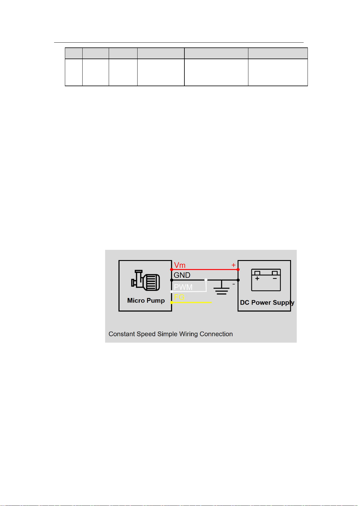
5.2 Logical Wiring Diagram
When the speed control function is not needed, the white connection
wire PWM input signal and the black connection wire can be
grounded together, the yellow wire must be insulated and wrapped,
and the micro pump will work at the rated speed.
Note: The speed feedback function is unavailable with the simplified version so there
is no yellow FG signal line.
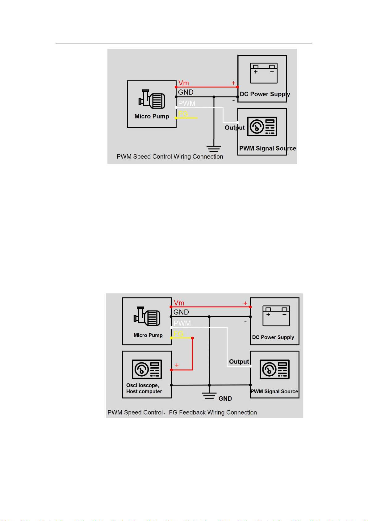
When you need to use the PWM speed control function, you need to
use a signal source that supports PWM signal output (unction signal
generator, MCU, PLC and other controllers), connect the signal
source output to the white PWM input wire, and connect the PWM
signal source ground to the DC power ground. If you do not need to
monitor the speed feedback signal, the FG signal line must be
insulated and wrapped. The speed feedback function is unavailable
with the simplified version so there is no yellow FG signal line.
C15 Flow Control Vacuum Pump Series User Guide
Copyright © Chengdu Hilin Technology Co., Ltd.
9
When you need to use the PWM speed control function and obtain
the FG feedback, you need to use a signal source that supports PWM
signal output (function signal generator, MCU, PLC and other
controllers) and an oscilloscope or host computer, and connect the
signal source output to the white PWM input. Connect the PWM
signal source ground to the DC power ground, connect the yellow
FG feedback signal line to the oscilloscope probe or the host
computer input, and connect the oscilloscope or host computer
ground wire to the black ground wire. If the FG signal wire is not
used, it must be insulated and wrapped. The speed feedback function
is unavailable with the simplified version so there is no yellow FG
signal line.

C15 Flow Control Vacuum Pump Series User Guide
Copyright © Chengdu Hilin Technology Co., Ltd.
10
6Cautions
Please read the instructions in this chapter carefully and follow
the instructions strictly before use.
1. This product has no waterproof, dust-proof, and explosion-proof
functions and cannot be used in flammable and explosive environments!
2. Foreign matter must not fall into the pneumatic connectors, and
there should be no solid particles in the medium, otherwise the micro
pump will be damaged!
3. The outlet must be kept unobstructed, otherwise the micro pump will
be damaged!
4. When this product is used to transfer harmful medium, it must be
double-sealed to ensure personal safety!
5. The matching piping components and containers must have
sufficient strength to ensure personal safety!
6. Please operate strictly in accordance with the instructions!!
C15 Flow Control Vacuum Pump Series User Guide
Copyright © Chengdu Hilin Technology Co., Ltd.
11
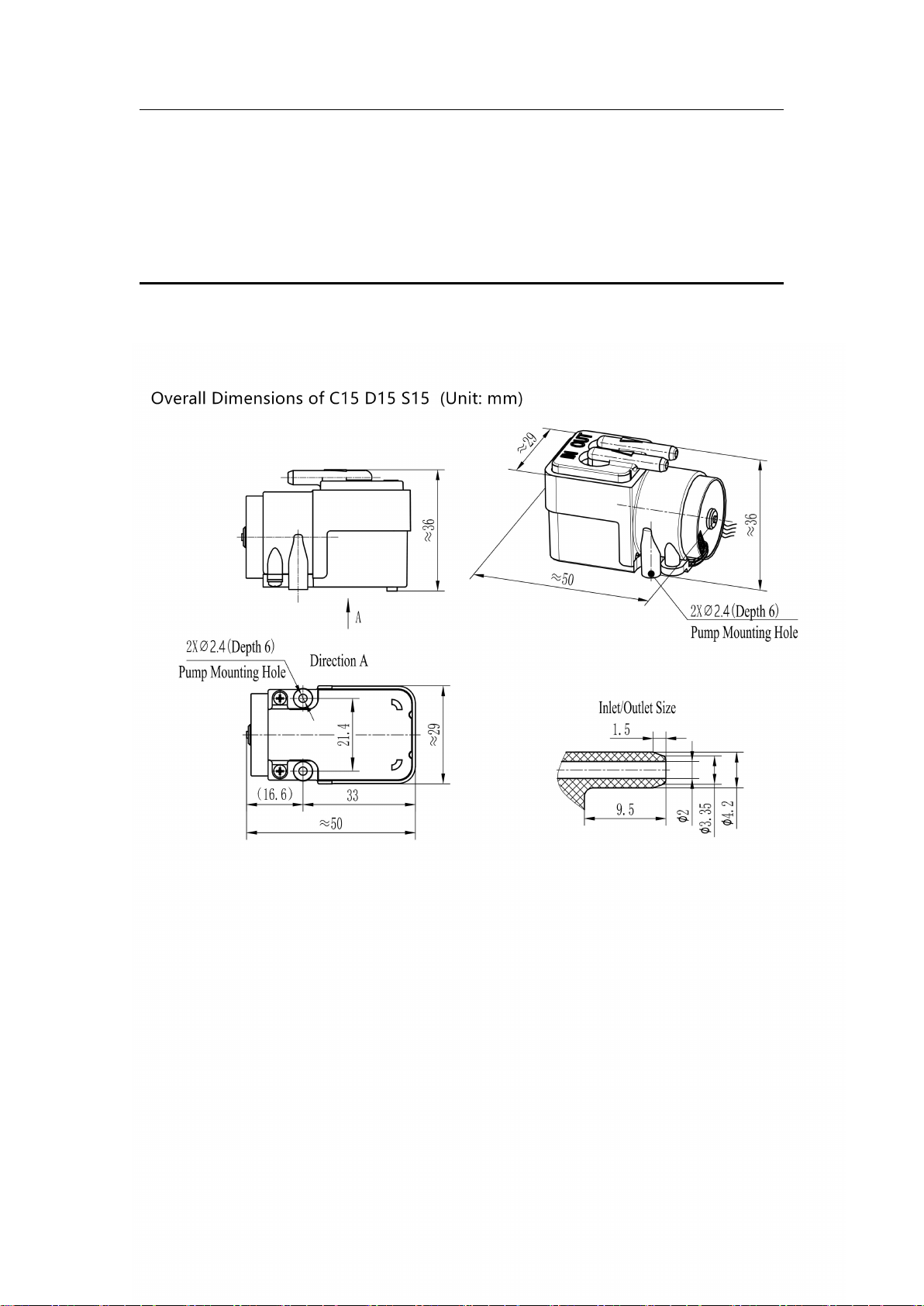
7Dimensions
Installation instructions:
1. The screws on the pump cannot be removed, otherwise it will damage the
pump;
2. The mounting hole is a self-tapping screw hole. Repeated disassembly is
prohibited, otherwise the installation will be loose and unreliable.

C15 Flow Control Vacuum Pump Series User Guide
Copyright © Chengdu Hilin Technology Co., Ltd.
12
8Appearance
Other manuals for C15
1
This manual suits for next models
1
Table of contents
Other Hilintec Water Pump manuals


Popular Water Pump manuals by other brands

GORMAN-RUPP PUMPS
GORMAN-RUPP PUMPS T10A60S-BF6L Installation, operation, and maintenance manual with parts list

Calpeda
Calpeda MXV Original operating instructions

salmson
salmson SXS Installation and starting instructions

U.S. Products
U.S. Products FLOOD KING 240V Information & operating instructions

GORMAN-RUPP PUMPS
GORMAN-RUPP PUMPS PA6H60-4045H FT4-ESP Installation, operation and maintenance manual

Anest Iwata
Anest Iwata DPS 90 F Series Instruction, use and maintenance manual


