Hillrom Primo P02033 User manual


PROPRIETARY AND CONFIDENTIAL DRAFT September 24, 2012
2
3
Primo™Service Manual - 171636(1)
Hill-Rom Industries S.A.
188, Rue du Caducée
Parc Euromédecine
34195 MONTPELLIER Cedex 5 - FRANCE
Tel: +33 (0)4 67 04 64 04
Fax: + 33 (0)4 67 04 64 00
www.hill-rom.com
First edition
First printing, 2012
Printed in Europe
171636, Rev.001 / September 2012
The information contained in this manual is confidential and may not
be reproduced or divulged in any form or by any means without the
prior written permission of Hill-Rom.
Hill-Rom®
is a registered trademark
of Hill-Rom Services, Inc.
I-mmersion™is a trademark of
Hill-RomServices, Inc.
Primo™
is a trademark of Hill-Rom Services, Inc.
Torx® is a registered trademark of Textron, Inc.
Hill-Rom reserves the right to make changes to the design,
characteristics and models without prior notice. The only warranty
Hill-Rom makes is the express written warranty extended on the sale or
rental of its products.
To order copies of this manual, refer to the last page, identify your
national Hill-Rom representative and order the article with the part
number 171636.
© 2012 by Hill-Rom Services, Inc. ALL RIGHTS RESERVED
Revision N° Affected pages Date
001 Original September 2012

PROPRIETARY AND CONFIDENTIAL DRAFT September 24, 2012
2
3
Primo™Service Manual - 171636(1) Page i
Table of Contents
Chapter 1:
Introduction
Introduction . . . . . . . . . . . . . . . . . . . . . . . . . . . . . . . . . . . . . . . . . . . . . . . . . . . . . . . . 1 - 1
Typographical conventions used in this manual . . . . . . . . . . . . . . . . . . . . . . . . . . . . 1 - 1
Precautions for use . . . . . . . . . . . . . . . . . . . . . . . . . . . . . . . . . . . . . . . . . . . . . . . . . . .1 - 1
Glossary of abbreviations . . . . . . . . . . . . . . . . . . . . . . . . . . . . . . . . . . . . . . . . . . . . . . 1 - 1
Warning labels:. . . . . . . . . . . . . . . . . . . . . . . . . . . . . . . . . . . . . . . . . . . . . . . . . . . . . . 1 - 2
Model identification . . . . . . . . . . . . . . . . . . . . . . . . . . . . . . . . . . . . . . . . . . . . . . . . 1 - 3
Identification label . . . . . . . . . . . . . . . . . . . . . . . . . . . . . . . . . . . . . . . . . . . . . . . . . 1 - 3
General description. . . . . . . . . . . . . . . . . . . . . . . . . . . . . . . . . . . . . . . . . . . . . . . . . . . 1 - 3
Technical specifications . . . . . . . . . . . . . . . . . . . . . . . . . . . . . . . . . . . . . . . . . . . . . . . 1 - 4
Operating principle. . . . . . . . . . . . . . . . . . . . . . . . . . . . . . . . . . . . . . . . . . . . . . . . . . . 1 - 5
Mechanical subsystem . . . . . . . . . . . . . . . . . . . . . . . . . . . . . . . . . . . . . . . . . . . . . . 1 - 7
Electric subsystem. . . . . . . . . . . . . . . . . . . . . . . . . . . . . . . . . . . . . . . . . . . . . . . . . . 1 - 8
Pneumatic subsystem . . . . . . . . . . . . . . . . . . . . . . . . . . . . . . . . . . . . . . . . . . . . . . . 1 - 9
Regulatory requirements . . . . . . . . . . . . . . . . . . . . . . . . . . . . . . . . . . . . . . . . . . . . . 1 - 10
End-of-life equipment . . . . . . . . . . . . . . . . . . . . . . . . . . . . . . . . . . . . . . . . . . . . . . . 1 - 10
Chapter 2:
Troubleshooting Procedures
Safety recommendations . . . . . . . . . . . . . . . . . . . . . . . . . . . . . . . . . . . . . . . . . . . . . . 2 - 1
Required tools. . . . . . . . . . . . . . . . . . . . . . . . . . . . . . . . . . . . . . . . . . . . . . . . . . . . . . . 2 - 1
Diagnostic tester . . . . . . . . . . . . . . . . . . . . . . . . . . . . . . . . . . . . . . . . . . . . . . . . . . . . . 2 - 1
Getting Started . . . . . . . . . . . . . . . . . . . . . . . . . . . . . . . . . . . . . . . . . . . . . . . . . . . . . . 2 - 2
Initial Actions . . . . . . . . . . . . . . . . . . . . . . . . . . . . . . . . . . . . . . . . . . . . . . . . . . . . . . . 2 - 3
Problem/Solution Table . . . . . . . . . . . . . . . . . . . . . . . . . . . . . . . . . . . . . . . . . . . . . 2 - 3
Final actions . . . . . . . . . . . . . . . . . . . . . . . . . . . . . . . . . . . . . . . . . . . . . . . . . . . . . . . . 2 - 3
Preventive maintenance instructions . . . . . . . . . . . . . . . . . . . . . . . . . . . . . . . . . . . . . 2 - 4
Operational checks . . . . . . . . . . . . . . . . . . . . . . . . . . . . . . . . . . . . . . . . . . . . . . . . . . 2 - 5
RAP 2.1 Electric power supply fault . . . . . . . . . . . . . . . . . . . . . . . . . . . . . . . . . . . 2 - 6
RAP 2.2 Mains power supply alarm fault . . . . . . . . . . . . . . . . . . . . . . . . . . . . . . . 2 - 7
RAP 2.3 Compressor fault . . . . . . . . . . . . . . . . . . . . . . . . . . . . . . . . . . . . . . . . . . . 2 - 8
RAP 2.4 Leak. . . . . . . . . . . . . . . . . . . . . . . . . . . . . . . . . . . . . . . . . . . . . . . . . . . . . 2 - 9
RAP 2.5 Malfunction alarm fault. . . . . . . . . . . . . . . . . . . . . . . . . . . . . . . . . . . . . 2 - 10
Chapter 3:
Procedures for
the removal, replacement and adjustment of parts
Preamble . . . . . . . . . . . . . . . . . . . . . . . . . . . . . . . . . . . . . . . . . . . . . . . . . . . . . . . . . . 3 - 1
Required tools . . . . . . . . . . . . . . . . . . . . . . . . . . . . . . . . . . . . . . . . . . . . . . . . . . . . . . 3 - 1
Prerequisites for all operations . . . . . . . . . . . . . . . . . . . . . . . . . . . . . . . . . . . . . . . . . 3 - 1
Symbols . . . . . . . . . . . . . . . . . . . . . . . . . . . . . . . . . . . . . . . . . . . . . . . . . . . . . . . . . . . 3 - 2
Replacing the mains socket fuse . . . . . . . . . . . . . . . . . . . . . . . . . . . . . . . . . . . . . . 3 - 2
Opening the control box . . . . . . . . . . . . . . . . . . . . . . . . . . . . . . . . . . . . . . . . . . . . 3 - 3
Replacing the front unit . . . . . . . . . . . . . . . . . . . . . . . . . . . . . . . . . . . . . . . . . . . . 3 - 4
Replacing the control PCB . . . . . . . . . . . . . . . . . . . . . . . . . . . . . . . . . . . . . . . . . . 3 - 4
Replacing the power PCB fuses . . . . . . . . . . . . . . . . . . . . . . . . . . . . . . . . . . . . . . 3 - 5
Replacing the power supply PCB . . . . . . . . . . . . . . . . . . . . . . . . . . . . . . . . . . . . . 3 - 5
Replacing the hoses . . . . . . . . . . . . . . . . . . . . . . . . . . . . . . . . . . . . . . . . . . . . . . . 3 - 6
Replacing the compressor . . . . . . . . . . . . . . . . . . . . . . . . . . . . . . . . . . . . . . . . . . . 3 - 7
Replacing the mains socket . . . . . . . . . . . . . . . . . . . . . . . . . . . . . . . . . . . . . . . . . 3 - 7
Replacing the unit at the back of the control unit . . . . . . . . . . . . . . . . . . . . . . . . . 3 - 8
Replacing the CPR valve . . . . . . . . . . . . . . . . . . . . . . . . . . . . . . . . . . . . . . . . . . . 3 - 9
Replacing the CPR valve on the pressure relief valve . . . . . . . . . . . . . . . . . . . . 3 - 10
Replacing the sensor . . . . . . . . . . . . . . . . . . . . . . . . . . . . . . . . . . . . . . . . . . . . . 3 - 11
Replacing the mattress . . . . . . . . . . . . . . . . . . . . . . . . . . . . . . . . . . . . . . . . . . . . 3 - 12

PROPRIETARY AND CONFIDENTIAL DRAFT September 24, 2012
2
3
Page ii Primo™Service Manual - 171636(1)

Introduction
Chapter 1: Introduction
PROPRIETARY AND CONFIDENTIAL DRAFT September 24, 2012
Primo™Service Manual - 171636(1) Page 1 - 1
3
4
2
1
Chapter 1
Introduction
Introduction
This manual contains the information required for the normal operation and
maintenance of the Hill-Rom Primo™. The part numbers of the spares can be
found in the catalog P/N 171353.
This manual is intended for use by facility-authorized personnel. Use by
unauthorized personnel may result in damage to the equipment and/or serious
injury to staff or users.
Typographical conventions used in this manual
This manual contains different typefaces and icons designed to improve
readability and increase understanding of its content. Note the following
examples:
• Standard text: used for regular information.
•Bold text: emphasizes a word or phrase.
•NOTE: sets apart special information or important instruction
clarification.
The symbols below represent different risks or hazards:
Precautions for use
Before using, it is essential to read the User Manual of the Primo™and this
Service Manual and to strictly follow all the safety instructions in these
manuals.
Caregivers must be informed of the risks that may be encountered in the use
of electric devices.
Glossary of abbreviations
Table 1-1. Glossary of abbreviations
Symbol Description
WARNING
• This symbol indicates that the failure to follow the associated
recommendation can put the patient or the user in danger, or
damage the equipment.
CAUTION
• This symbol indicates that the failure to follow the associated
recommendation can result in damage to the equipment.
Electric Shock Hazard
Abbreviations Definition
CPR Return the head section to the flat position for cardio-
pulmonary
reanimation
I-mmersion™Trade mark: pressure control system
EV Electro valve
RAP Repair Analysis Procedure
P/N Part number

Warning labels:
Chapter 1: Introduction
PROPRIETARY AND CONFIDENTIAL DRAFT September 24, 2012
2
3
Page 1 - 2 Primo™Service Manual - 171636(1)
Warning labels:
Figure 1-1. Control unit
Figure 1-2. Power PCB
A Identification labels
B Seat cushion inflation port
C
Fuses for 220-240 VAC
Fuses for 120 VAC
AB
C
D
Refer to the user manual.
(if the battery fails, replace the power supply
PCB - follow procedure 3.6 page 3-5).
EWarning:
High voltage!
D
E

General description
Chapter 1: Introduction
PROPRIETARY AND CONFIDENTIAL DRAFT September 24, 2012
Primo™Service Manual - 171636(1) Page 1 - 3
3
4
2
1
Model identification
Refer to the table below to identify the models of the Primo™Therapeutic
Mattress.
Table 1-2. Model Identification
Identification label
Figure 1-3. Identification label
NOTE:
This procedure applies to class II*models which are identified by a P,
followed by five numbers, from version A onwards (see figure 1-3 page 1-3).
For all earlier versions, refer to the Service Manual P/N W10006.
Class II devices are identified by the symbol on the label.
General description
The Primo™
helps to prevent and treat pressure ulcers in all adult patients,
exposed to low to moderate risks
.
The pressure in the air bladders is automatically regulated by the innovative
I-mmersion™pressure control system.
This patented technology permanently detects the weight and position of the
patient's body and dynamically adjusts the pressure in the mattress.
Figure 1-4. Exploded view of the Primo™
Name Part
number Technical characteristics
Primo 85x200 P02033 220 - 240V ~, 50/60Hz
Primo 85x200 P02034 120V ~, 60Hz
Primo 77x200 P02044 220 - 240V ~, 50/60Hz
Primo 85x200 FIRE P02047 220 - 240V ~, 50/60Hz
P02033 A
P+5 figures = model B = product version letter
1
2
3
5
4
6
7
8
8
9

Technical specifications
Chapter 1: Introduction
PROPRIETARY AND CONFIDENTIAL DRAFT September 24, 2012
2
3
Page 1 - 4 Primo™Service Manual - 171636(1)
Table 1-3. Description Technical specifications
Table 1-4. Control unit
Item Name
1 Upper cover
2 Air mattress
3 Control unit
4Sensor
5 Foam sub-mattress
6 Bottom cover
7CPRvalve
8Straps
9Sensorunit
Characteristics Description
Model P02033 P02047 P02034 P02044
Dimensions 15x29x12 cm / 6x11.5x5"
Weight 3,5 kg / 8 lb
Power supply 220-240V
50/60 Hz
220-240V
50/60 Hz 120V 60Hz 220-240V
50/60 Hz
Apparent power 20 VA 20 VA 32 VA 20 VA
Maximum energy
consumption 16.4 Wh 16.4 Wh 16.4 Wh 16.4 Wh
Operation of the device Continuous
Sleeve material ABS PC V0
Device: Acoustic
pressure / power
(ISO 3744)
41 dB(A) / 52 dB(A)
Alarm: Acoustic
pressure / power
(IEC60601-1-8)
56 dB(A) / 67 dB(A)
Fuse T160 mA T160 mA T200 mA T160 mA
Compression 0-180 mBar 0-180 mBar 0-215 mBar 0-180 mBar
Maximum compressor
flow rate 10 l/min 10 l/min 12 l/min 10 l/min
IEC 60601-1
classification Class II
Degree of protection
provided by the unit
(IEC 60529)
IP21: protected against access to dangerous parts with
fingers and vertically dripping water
Protection against
inflammable anesthetic
mixtures
Not for use with flammable anesthetics
Battery life 1 hour

Operating principle
Chapter 1: Introduction
PROPRIETARY AND CONFIDENTIAL DRAFT September 24, 2012
Primo™Service Manual - 171636(1) Page 1 - 5
3
4
2
1
Table 1-5. Therapeutic Mattress Table 1-6. Conditions for transport, storage and use
Operating principle
The operation of the Primo™can be split into three categories or subsystems:
• Mechanical subsystem
• Electric subsystem
• Pneumatic subsystem
The device operates thanks to the combined functions of these three
subassemblies.
These three subassemblies must operate correctly with one another for the
device to function correctly.
Each of these subassemblies is described separately in the following sections.
Characteristics Val ues
Model P02033/P02047/P02034 P02044
Length (inflated) 200 cm / 79"
Width (inflated) 85 cm / 33.5" 77 cm / 30.5"
Height (inflated) 16 cm / 6"
Weight 8,4 kg / 18.5 lb
Operation in transport mode 2 hours
Upper cover
Polyurethane coating on polyester material
Low-friction, stretchable in both directions, breathing,
bacteriostatic, fungistatic and antimicrobial. Can be
wiped and washed.
Bladders Polyurethane
Safe working load,
including the total weight of the patient, accessories (if
they are supported by the support system of the medical
bed) and the load supported by these accessories
(excluding the weight of the patient).
Maximum pressure of the
safety valve 1 psi / 69 mBar
Degree of protection against
electric shock
Type BF applied parts protected against defibrillation
shocks (items 1 and 6 page 1-3)
Degree of protection
provided by the cover
(IEC 60529)
IP24: protected against access to dangerous parts with
fingers and splashes of water
250 250
Symbol
Features
Use Transport/storage15a
a. Applicable only if the device is stored in its original packaging.
Temperature
+5°C - +40°C -25°C - +70°C
Humidity
15%-93% 0%-93%
Atmospheric
pressure
700 mbar - 1,060 mbar 700 mbar - 1,060 mbar
Operating principle
Chapter 1: Introduction
PROPRIETARY AND CONFIDENTIAL DRAFT September 24, 2012
2
3
Page 1 - 6 Primo™Service Manual - 171636(1)
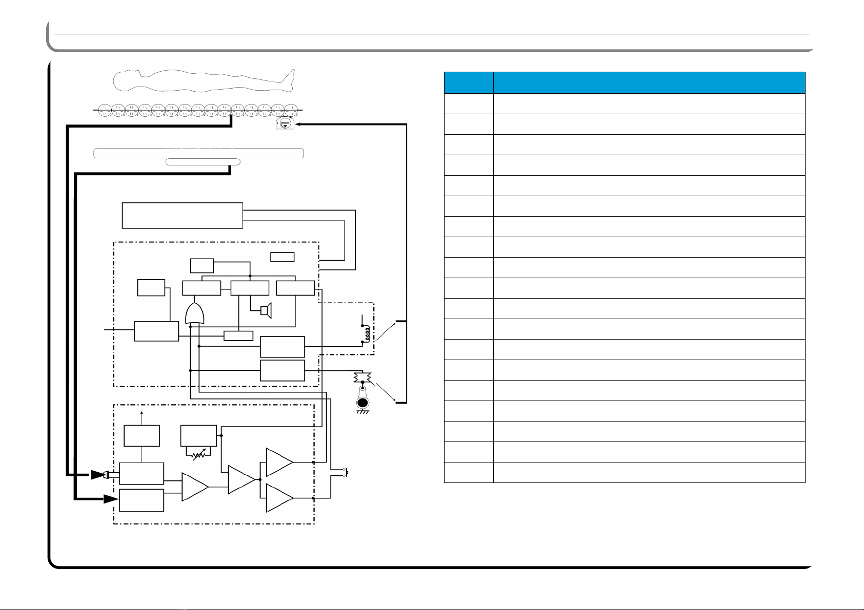
Figure 1-5. Overview Table 1-7. General description
PATIENT
Sensor
Valve control board
Power supply PCB
Regulation PCB
AIR
1
8
6
7
10
11
Mains supply
9Solenoid
Compressor
12
13
15
17
14
AIR
3
2
45
16
18
19
Item Name
1Clock
2Battery
3 Malfunction alarm time delay
4 Alarm silence time delay
5 Compressor override time delay
6Alarm
7 Mains power alarm
8 On/Off switch
9 +12V power
10 Leak control
11 Compressor control
12 Power supply
13 Air pressure transducer
14 Sensor signal conditioning
15 Set point adjustment
16 Amplifier
17 Integrator
18 High comparator
19 Low comparator

Operating principle
Chapter 1: Introduction
PROPRIETARY AND CONFIDENTIAL DRAFT September 24, 2012
Primo™Service Manual - 171636(1) Page 1 - 7
3
4
2
1
Mechanical subsystem
CPR valve
The CPR valve is at the foot of the mattress. Turn the yellow valve clockwise
(A) to activate the CPR. Activating the CPR deflates the mattress in less than
20 seconds.
Turn the yellow valve (B) anti-clockwise to its original position to deactivate
the CPR.
Seat cushion connector
The seat cushion connector used to inflate the cushion is on the left-hand side
of the control unit. It is available as an option.
Figure 1-6. Wiring and electrical distribution
AB
Sensor
Control PCB
Power supply PCB
1 Phase - 230VAC
2 Spare
3 Spare
4 Spare
5 Neutral - 230VAC
J1 - Mains power
Compressor
1 Neutral - Compressor
2 Spare
3 Spare
4 Spare
5 Phase - Compressor
J2 - Compressor
1 On/Off switch LED
2 On/Off switch
3 Inflate cushion
4 Inflate cushion LED
5 Silence alarms
6
7 Mains fault alarm LED
8 Malfunction alarm LED
9 +5VDC
10 +12VDC
J3 - Control panel
Operating principle
Chapter 1: Introduction
PROPRIETARY AND CONFIDENTIAL DRAFT September 24, 2012
2
3
Page 1 - 8 Primo™Service Manual - 171636(1)
Electric subsystem
All the major systems are protected by fuses.
The fuses are located:
• on the mains power socket (See “Replacing the mains socket fuse” page
3-2);
• at input of mains transformer, marked F1 on the power PCB (See
“Replacing the power PCB fuses” page 3 - 5);
• at output of solid-state relay of the compressor, marked F2 on the power
PCB (See “Replacing the power PCB fuses” page 3 - 5).
The I-mmersion™control circuit constitutes the heart of the system:
• It automatically compensates for patient/bed position changes and
supports the patient at the optimal pressure.
• It automatically corrects the pressure in the bladders.
• It automatically compensates most variations due to external parameters.
Control unit
The control unit contains a rechargeable battery on the power PCB. It powers
the mains supply alarm in the event of a power cut.
The control unit panel is the main means of controlling the Primo™. It
contains the minimal functions and provides the user with feedback on the
status of the device and any malfunctions that may occur.
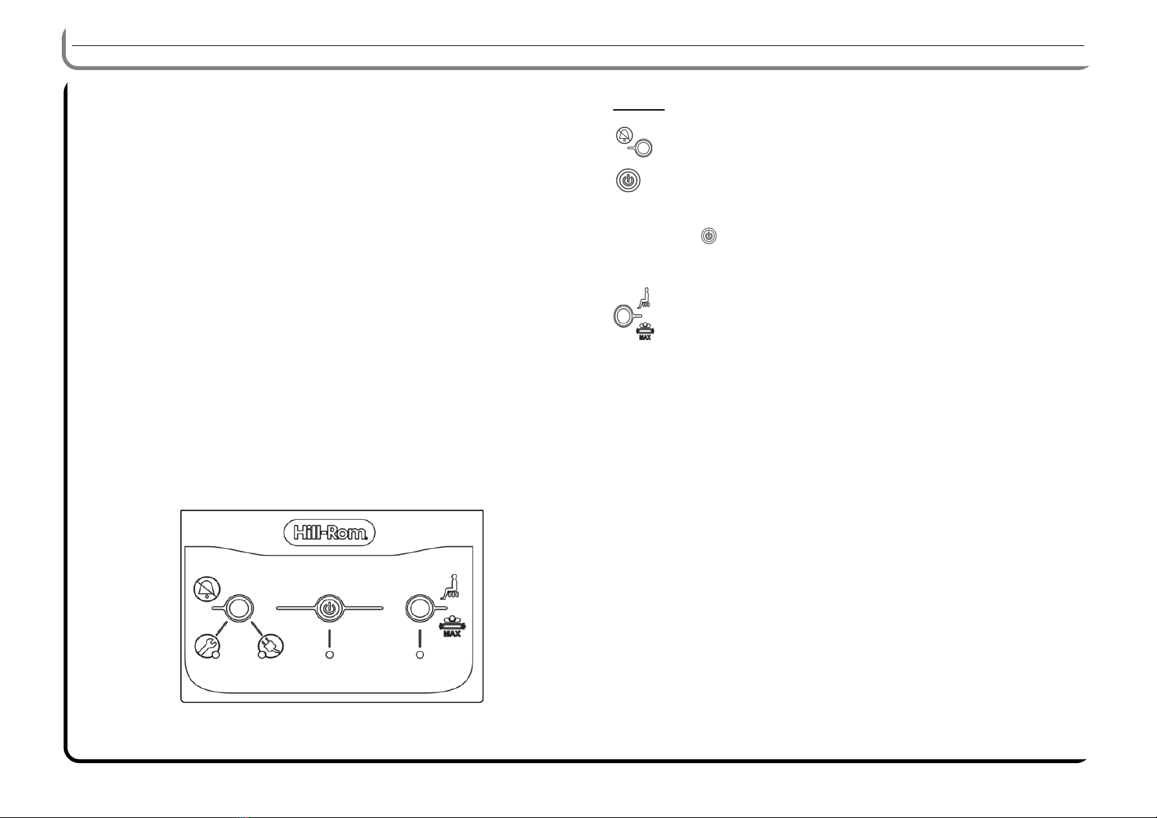
Figure 1-7. Control unit panel
Buttons and indicator lights
Buttons
1 - Audio alarm silence:
deactivates the Mains fault and Malfunction audio alarms.
2 - On/Off.
NOTE:
To switch off the mains power supply:
press to cut out the battery. In this case, no mains power supply
fault alarms will be raised;
Unplug the device from the wall socket.
3 - Maximum inflate:
increases the pressure in the mattress to the maximum value for
5 minutes and automatically returns to therapeutic mode.
Is also used to inflate the seat cushion.
ABCD
123

Operating principle
Chapter 1: Introduction
PROPRIETARY AND CONFIDENTIAL DRAFT September 24, 2012
Primo™Service Manual - 171636(1) Page 1 - 9
3
4
2
1
Indicators / alarms
(see figure 1-7 page 1-8)
A - Malfunction alarm:
the audio alarm sounds and the yellow visual alarm lights up after
about 10 minutes, when:
• the sensor is faulty;
• the sensor is disconnected;
• CPR mode is active;
• the mattress is damaged (tears, leaks, damaged couplings, etc).
The audio alarm sounds and the yellow visual alarm lights up after
about 20 minutes, when:
• the pressure in the mattress drops below 4″H2O +/- 0.8"H2O
(10 mbar +/- 2 mbar);
B - Mains power fault alarm:
The audio alarm sounds and the yellow visual alarm lights up
immediately, in the event of:
• electric power cut;
• damaged power supply cable;
• accidental disconnection of the power supply cable;
• fuse on the mains power supply socket, or fuse F1 on the power
supply PCB damaged;
• transport.
C - On/Off indicator light:
the green light comes on when the control unit is on.
D - Inflation indicator:
the green light flashes for 5 minutes as the mattress is inflated.
I-mmersion™sensor
The I-mmersion™sensor, which has its own PCB, uses resistive variation due
to the applied force. When the patient's sacrum presses against the mattress,
this pressure is transmitted to the sensor as a force. The variation in the
resistivity of the sensor is measured. A signal is then sent to the control unit to
deflate or inflate the mattress, until the pressure in the mattress is equal to the
pressure of the sensor.
By calibrating the balance of the I-mmersion™sensor, the servo-control
always optimizes the support of the patient, irrespective of their weight or
position (within the limits specified in page 1-5).
CPR valve
In CPR mode, the regulation functions normally, the compressor remains
under control, but not the leak solenoid.
The yellow visual alarm lights up
to indicate that that the pressure is low
.
A low-priority alarm sounds
immediately, intermittently and at a moderate volume.
Pneumatic subsystem
The air is drawn into the control unit through the air filter. The air filter limits
the ingress of dust, which could clog the pneumatic circuit. The air then flows
into the compressor inlet.
When the air leaves the compressor, it is distributed between the bladders in
the mattress, the mattress/seat cushion coupling and the pressure relief valve
on the electric power supply PCB.
Two-tier mattress
The mattress is made up of two levels:
• a therapeutic mattress;
• a foam sub-mattress, which includes the sensor unit, and a lower cover
that includes the sensor.
The therapeutic mattress is a single piece made up of a series of 15 airtight
bladders. The air pressure in these bladders is the same as the pressure in the
sensor in the lower cover.
The I-mmersion™detector is located beneath the sacrum zone of the
therapeutic mattress.
Regulatory requirements
Chapter 1: Introduction
PROPRIETARY AND CONFIDENTIAL DRAFT September 24, 2012
2
3
Page 1 - 10 Primo™Service Manual - 171636(1)
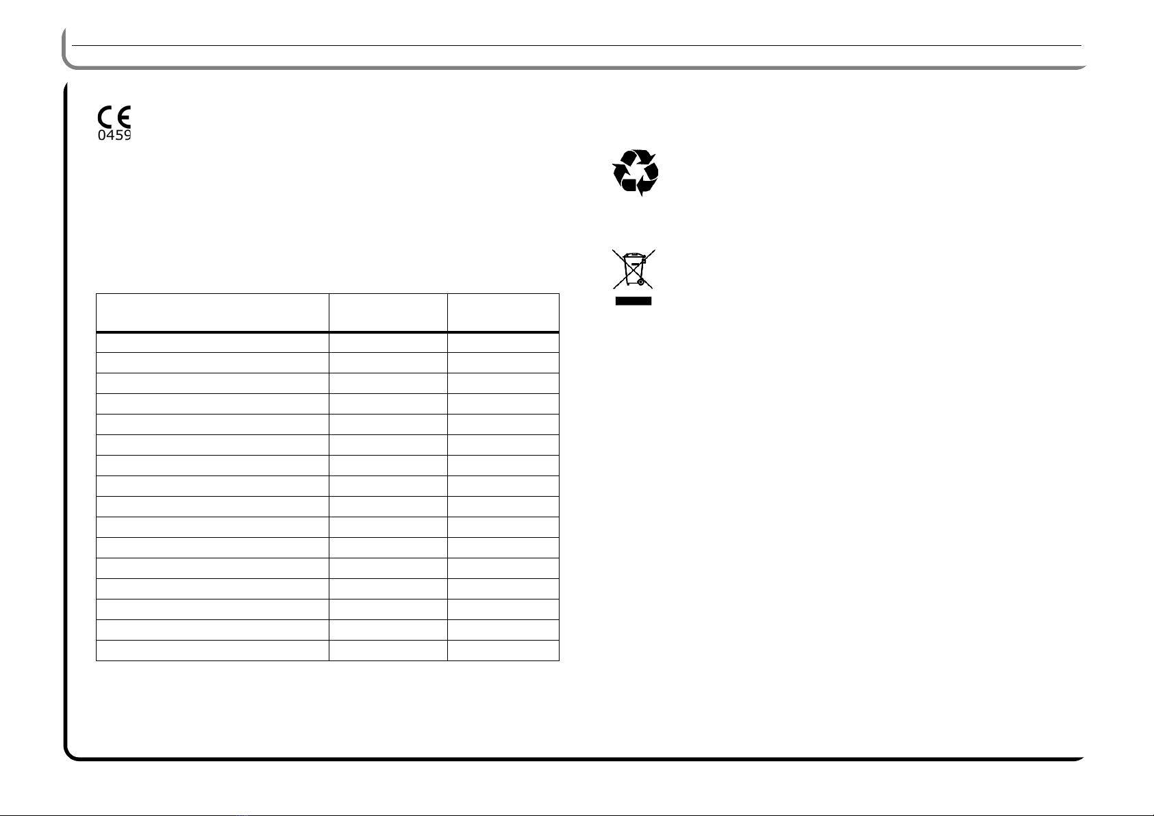
Regulatory requirements
The Primo™is a class IIa medical device that complies with the
requirements of Directive 93/42/EC and its amendments.
The CE mark was applied in 1998.
The Primo™is designed and manufactured in accordance with the following
standards and classifications:
Quality standards:
Technical standards:
End-of-life equipment
The Primo™and its accessories should be cleaned and disinfected before
de-commissioning.
Decommissioned equipment materials (plastics, electrical
components, etc.) must be recycled in accordance with local
recycling regulations. Always meet the applicable demands and local
rules relating to environmental protection, in particular for waste
from medical devices.
Do not dispose of electric and electronic equipment in the waste bin
(as per directive 2012/19/EC).
Never discard the batteries or accumulators of your device. They
may contain substances and metals that are hazardous for the
environment and health (as per Directive 2006/96/EC).
- ISO 9001: 2008 - ISO 13485: 2012 - ISO 14001: 2004
Name P02033/P02034/
P02044
P02047
EN IEC 60601-1: 2006 YES YES
EN IEC 60601-1-2: 2007 YES YES
EN IEC 60601-1-6: 2010 YES YES
EN IEC 60601-1-8: 2007 YES YES
EN IEC 60601-1-11: 2010 YES YES
EN ISO 14971: 2012 YES YES
EN ISO 10993-1: 2009 YES YES
EN ISO 10993-5: 2010 YES YES
EN ISO 10993-10: 2009 YES YES
EN ISO 980: 2009 YES YES
EN 597-1: 1995 YES YES
EN 597-2: 1995 YES YES
SS 876 00 01 (NT FIRE 037) YES YES
UNI 9175: 2008 (Class 1 IM) NO YES
BS 6807: 2006, Clause 9, Ignition/5 NO YES
BS 7177: 1996 (Medium hazard) NO YES

PROPRIETARY AND CONFIDENTIAL DRAFT September 24, 2012
Primo™Service Manual - 171636(1) Page 2 - 1
3
4
2
1
Chapter 2
Troubleshooting Procedures
Safety recommendations
Never modify this device without Hill-Rom's prior written consent.
Only facility-authorized personnel should perform maintenance.
Changes made by unauthorized personnel may result in damage to the
equipment and/or serious injury to staff or users.
Before maintenance or servicing works:
• Check that the brakes are applied on the bed on which the mattress is
installed.
• Lock out all electrical functions.
• Unplug the device.
• Secure the mattress support platform and take whatever steps are
necessary to prevent any movement.
Required tools
The following tools are required to troubleshoot the Primo™therapeutic
mattress:
• clamping pliers (P/N: G01008);
• digital pressure gauge kit (P/N G05003);
• diagnostic tester (P/N G05002);
• 25kg test load (P/N G02004).
For details of the list of tools, refer to the spare parts catalog (P/N: 169854).
NOTE:
Refer to the following at the start of each RAP if necessary:
• "Glossary of abbreviations" page 1-1 for the meaning of the
abbreviations used in this manual.
Diagnostic tester
The diagnostic tester is used to detect fault signals between the control unit
and the sensor. Connector on the normal connection of the CPR valve
(see figure below).
Figure 2-1. Connection of the diagnostic tester to the CPR valve

Getting Started
Chapter 2: Troubleshooting Procedures
PROPRIETARY AND CONFIDENTIAL DRAFT September 24, 2012
2
3
Page 2 - 2 Primo™Service Manual - 171636(1)
The diagnosis tester is used to:
• measure the 12 V DC supply voltage of the I-mmersion sensor;
• check the inflation signal sent by the I-mmersion sensor;
• check the deflation signal sent by the I-mmersion sensor;
• check the temporary inflation signal sent by the power PCB when the
seat cushion inflate function is activated.
Figure 2-2. Indicator lights (LED) on the diagnostic tester
Getting Started
Start all of the procedures in this Chapter at step 1. Follow the indicated order.
Each step assumes that the preceding steps have been correctly completed.
Each step corresponds to the normal operation of the product. Please answer
"Yes" or "No" to the question. If more than one component is listed, replace
them in the given order, and re-install the original component that was found
to be OK.
1. To begin gathering information about the problem, start with the initial
actions.
2. Perform functional checks to locate/identify a problem and check the
repair after every corrective action (e.g., replacing or adjusting a part,
installing a cable).
3. To verify the repair, perform the final actions after the function
checks.
If the troubleshooting procedures do not isolate the problem, call your
national Hill-Rom Technical Support (see back cover) for assistance.
NOTE:
The purpose of the proposed troubleshooting method is to limit as much as
possible the number of spare parts required and costs when analyzing the
failure.

Initial Actions
Chapter 2: Troubleshooting Procedures
PROPRIETARY AND CONFIDENTIAL DRAFT September 24, 2012
Primo™Service Manual - 171636(1) Page 2 - 3
3
4
2
1
Initial Actions
Use the initial actions to gather information from operators concerning
problems with the Primo™. Note the symptoms and all other information
concerning the problem that the operator describes. This information helps
identify the probable cause.
Problem/Solution Table
If the problem can be easily identified, use the following tables to determine
the appropriate troubleshooting procedure.
Table 2-1. Problem/Solution Table
Final actions
1. Perform the required preventive maintenance procedures. Refer to the
"Preventive maintenance form" in the PM-PDI manual (P/N: 172559).
2. Complete all required administrative tasks.
Someone who can explain the problem is
available.
Is the problem a result of improper
operator action?
Ask this person to demonstrate or explain
the problem.
The problem can be
duplicated.
Instruct the operators to refer to the
procedures in the User Manual of the
Primo™.
See ”Operational checks”
page 2-5
See "Problem/Solution Table"
page 2-3
Has the faulty function been identified?
Problem Solution
The system does not start “RAP 2.1 Electric power supply fault”,
page 6
The audible mains fault alarm does not
sound
“RAP 2.2 Mains power supply alarm
fault”, page 7
The compressor does not start “RAP 2.3 Compressor fault”, page 8
The compressor does not stop “RAP 2.4 Leak”, page 9
The audible malfunction alarm does
not sound
“RAP 2.5 Malfunction alarm fault”,
page 10

Preventive maintenance instructions
Chapter 2: Troubleshooting Procedures
PROPRIETARY AND CONFIDENTIAL DRAFT September 24, 2012
2
3
Page 2 - 4 Primo™Service Manual - 171636(1)
Preventive maintenance instructions
Refer to the “Preventive maintenance and Pre-Delivery Inspection Instructions” (P/N: 172559).
The frequency of inspections must be adapted to the general condition of the product and its use, for example, if the overlay is used by heavy patients. It is the
responsibility of the facility to implement a preventive maintenance program for the mattress functions under its conditions of use.
The mattress and accessories should be inspected at least once a year to keep them in good condition and working properly.
Every three years, it is preferable to ask Hill-Rom After-Sales Service or a Hill-Rom approved supplier to inspect the device in order to keep it in safe and good
working order over time. Depending on the maintenance operations and observations, the date of the next inspection must be recommended every time the bed is
serviced.
In order to benefit from optimal and rapid service when calling Hill-Rom about your Primo™, provide the serial number of the system about which you are calling.

Operational checks
Chapter 2: Troubleshooting Procedures
PROPRIETARY AND CONFIDENTIAL DRAFT September 24, 2012
Primo™Service Manual - 171636(1) Page 2 - 5
3
4
2
1
Operational checks
Operational checks
Connect the system.
Does the compressor
stop after about 20
minutes?
Does the On/Off
indicator light come
on? "RAP 2.1 Electric power
supply fault" page 2-6
"RAP 2.2 Mains power
supply alarm fault" page
2-7
The compressor starts.
Activate the CPR valve.
Press .
Unplug the device.
The visual and
audible mains
fault alarms are
activated.
The visual and audible
mains fault alarms are
activated after 10 minutes.
Perform the Final actions on
page 2-3.
"RAP 2.3 Compressor
fault" page 2-8
Is the pressure
stable between
7
and 9" H
2
0
?
"RAP 2.4 Leak" page 2-9
"RAP 2.5 Malfunction alarm
fault" page 2-10
Connect the pressure gauge to
the seat cushion connector.
Activate the CPR valve for 10
seconds then deactivate it.
Replace the (see procedure
3.13 page 3-11) sensor.
The audible alarm
sounds.
Replace the power supply PCB
(see procedure 3.6 page 3-5).
Connect the system.
The problem is solved.
The problem is solved.
Contact your
Hill-Rom
representative (see last
page of the manual).

Operational checks
Chapter 2: Troubleshooting Procedures
PROPRIETARY AND CONFIDENTIAL DRAFT September 24, 2012
2
3
Page 2 - 6 Primo™Service Manual - 171636(1)
RAP 2.1 Electric power supply fault
RAP 2.1
Electric power supply fault
Disconnect the device
from the mains.
Connect the device again
The fuse is faulty.
Inform the customer that
the connector is faulty.
Check the fuse in the
control unit (see procedure
3.1 page 3-2).
Connect the device to
another functional power
source.
Perform the Operational
checks on page 2-5.
Replace the fuse (see
procedure 3.5 page 3-5).
The wall socket is live.
The On/Off indicator
light comes on.
The On/Off indicator
light comes on.
Disconnect the device from
the mains.
Open the control unit (see
procedure 3.5 page 3-5).
The mains socket is
disconnected (J1) or
damaged?
Replace the fuse.
Connect the device
Close the control unit.
Replace the power supply
PCB(see procedure 3.6
page 3-5).
Connect the mains socket to
J1 (see figure 1-6 page 1-7)
or replace it, where
appropriate (see procedure
3.9 page 3-7).
Fuse F1 is faulty.
Replace the power
cable.
The On/Off indicator
light comes on.
Replace the control PCB
(see procedure 3.4 page
3-4).
Other manuals for Primo P02033
1
This manual suits for next models
3
Table of contents
Other Hillrom Indoor Furnishing manuals


Popular Indoor Furnishing manuals by other brands


BIG FURNITURE WAREHOUSE
BIG FURNITURE WAREHOUSE NORDICA 2 DRAWER LOW COFFEE TABLE Assembly instructions

Vivo
Vivo MOUNT-KB05GP instruction manual

Teknik
Teknik Boulevard Cafe Series Assembly instructions

Home Decorators Collection
Home Decorators Collection Manhattan WSHCSSU Assembly instructions

Novogratz
Novogratz Bushwick 4044449N manual

Great Little Trading
Great Little Trading Star Bright L4944 quick start guide


