Hillyard TRIDENT XM13SC User manual
SERVICE MANUAL
TRIDENT XM13SC
Version: AB
Date: October 4, 2017
Document Number:10055555

Contents
I Product Introduction 4
1 Serial Number and Technical Support 5
1.1 The Serial Tag ................................. 5
1.2 Serial Tag location ............................... 5
2 Main Technical Features 6
II Anomalies Resolution Guide 7
3 Troubleshooting Guide 8
3.1 Basic Guide ................................... 8
3.2 Advanced Guide ................................ 13
4 Disassembling Procedures 19
4.1 Electrical Installation ............................. 20
4.2 Mechanical Friction System ......................... 22
4.3 Drying System ................................. 23
4.4 Frame and Traction System ......................... 24
4.5 Solution Delivery System ........................... 25
III Machine Description 26
5 Electrical System 27
5.1 Structure .................................... 27
5.2 Description ................................... 27
5.3 Location of Electrical components ...................... 28
5.4 Maintenance and Checks ........................... 32
5.5 Programming .................................. 33
5.6 Alarm Table ................................... 36
5.7 Menu tables ................................... 37
6 Mechanical Rubbing System 40
6.1 Structure .................................... 40
6.2 Description: ................................... 40
6.3 Maintenance and checks ........................... 41
2

7 Drying System 43
7.1 Structure .................................... 43
7.2 Description ................................... 43
7.3 Adjustments .................................. 44
7.4 Maintenance and Checks ........................... 44
8 Machine Frame and Traction System 47
8.1 Structure .................................... 47
8.2 Description ................................... 47
8.3 Maintenance and Checks ........................... 47
9 Cleaning Solution Supply System 48
9.1 Structure .................................... 48
9.2 Description: ................................... 48
9.3 Maintenance and Checks ........................... 49
10 Consumable & Recommended Spare Parts 50
10.1Consumable Spare Parts ........................... 50
10.2Recommended Spare Parts .......................... 51
3

Part I
Product Introduction
4

Chapter 1
Serial Number and Technical Support
1.1 The Serial Tag
1.2 Serial Tag location
To have access to the Serial Tag it is sufficient to remove both tanks.
The Serial Number is an extremely important information which has to be provided
each time a Technical Support is required or is necessary to buy spare parts or
accessories. The serial number is the only way to identify the machine by model,
production date type equipments in general.
5

Chapter 2
Main Technical Features
Technical Data
TECHNICAL DESCRIPTION U/M XM13SC
Working Width in 11
Working Capacity, up to ft2
h9687
Brush Diameter/Revolutions φin-rpm 11-150
Brush Motor Voltage/Power V-W 36-90
Max Weight on brush lb 22
Total Power W 255
Squeegee Width in 12,8
Solution Tank gal 0,8
Recovery Tank gal 1
Vacuum Motor Voltage/Power V-W 36-150
Machine Length (Handlebar Up - Down) in 21,8-35,2
Machine Height (Handlebar Up - Down) in 41,3-13,8
Machine Width in 14,8
Sound pressure level (ISO 11201) LpA dB (A) ≤76
Hand vibration level (ISO 5349) m
s2≤2.5
Weights and Pressures1
TECHNICAL DESCRIPTION U/M XM13SC
Machine Weight (Machine + Brush + Squeegee) lb 40
Gross Weight of the machine in work conditions
(Machine + Battery+ Water + Brush + Squeegee)
lb 50
1Weight and Pressures depends on how much water there is in the tanks.
6

Part II
Anomalies Resolution Guide
7

Chapter 3
Troubleshooting Guide
3.1 Basic Guide
3.1.1 Electrical system: what to do if. . .
The machine doesn’t switch on
1. The main switch is not pushed ⇒Push the main switch.
2. The battery doesn’t work properly ⇒Refer to the proper section (see section
3.1.1 at page 8).
3. The problem is not solved ⇒Refer to the Advanced Guide (see section
3.2.2 at page 14).
The battery don’t work properly
1. The battery is not properly con-
nected
⇒Insert the battery until the end posi-
tion clicks.
2. The battery is discharged ⇒Perform a complete charge cycle.
3. The battery is faulty ⇒Refer to the Advanced Guide (see section
3.2.3 at page 15).
4. The battery charger doesn’t work ⇒Check the proper section (see section 3.1.1
at page 8).
8

The battery charger doesn’t work
1. The battery charger is not con-
nected to the power supply
⇒Connect the charger to a supplied
electric socket.
2. The charger has the power switch
in position 0
⇒Move the power switch in position 1.
3. The battery charger has the Red
LED blinking
⇒The battery charger is in error con-
ditions, verify the alarm tables and
solve the issue by following the re-
lated instructions (see section 5.3.5 at page
32).
4. The battery charger plugged in and
turned on does not activate the
Green LED (electrical continuity)
⇒Replace the battery charger.
5. The battery charger plugged in and
turned on with battery inserted
does not activate the Red LED
(charging)
⇒Make sure the battery is properly
positioned inside the slot and the
terminals have a good contact.
The battery may be already
charged.
The display shows an alarm message
1. The display shows an alarm mes-
sage
⇒Check what alarm message is
shown and solve the related issue
by following the proper instructions
(see section 5.6.1 at page 36).
The machine has a very limited working autonomy
1. The battery is discharged ⇒Perform a complete charge cycle.
2. The battery have been working for
several cycles
⇒Replace the battery.
9

3.1.2 Mechanical scrubbing system: what to do if. . .
The machine doesn’t clean well
1. The machine is switched off ⇒Switch on the machine.
2. The machine doesn’t switch on ⇒Refer to the proper section (see section
3.1.1 at page 8).
3. The display shows an alarm mes-
sage
⇒Check what alarm message is
shown and solve the related issue
by following the proper instructions
(see section 5.6.1 at page 36).
4. The switch ”Auto” is not pressed ⇒Press the ”Auto” switch.
5. The brush motor is not working ⇒Refer to the Advanced Guide (see section
3.2.5 at page 16).
6. The brush is not properly engaged ⇒Release and engage properly the
brush.
7. The solution flow rate is not correct
or not enough
⇒Refer to the proper section (see section
3.1.4 at page 12).
8. The detergent doesn’t fit the type of
dirt
⇒Replace the detergent with a proper
one.
10

3.1.3 Drying system: what to do if. . .
The machine doesn’t dry well
1. The machine is switched off ⇒Switch on the machine.
2. The machine doesn’t switch on ⇒Refer to the proper section (see section
3.1.1 at page 8).
3. The vacuum motor doesn’t work ⇒Refer to the Advanced Guide (see section
3.2.6 at page 18).
4. The machine is in ”ECO” mode ⇒Set up the machine as per standard
configuration.
5. The display shows an alarm mes-
sage
⇒Check what alarm message is
shown and solve the related issue
by following the proper instructions
(see section 5.6.1 at page 36).
6. The recovery tank is full ⇒Empty the recovery tank following
the proper procedure.
7. The squeegee is lifted up from the
floor
⇒Lower down the squeegee.
8. The squeegee rubber blades are
worn out or broken
⇒Rotate or replace the squeegee rub-
ber blades (see section 7.4.1 at page 44).
9. The squeegee is not properly ad-
justed
⇒Adjust the squeegee properly follow-
ing the proper procedure (see section 7.3.1
at page 44).
10. The squeegee vacuum chamber or
the adapter is stuck or dirty
⇒Clean the squeegee.
11. The vacuum hose is stuck or bro-
ken
⇒Clean or replace the vacuum hose.
12. The vacuum hose is not properly
fitted in
⇒Connect the vacuum hose properly.
13. The intake manifold is stuck or bro-
ken
⇒Clean or replace the intake manifold.
14. The vacuum cover is not well posi-
tioned or is missing
⇒Position properly the vacuum cover.
15. The vacuum cover gasket doesn’t
adhere properly
⇒Replace the vacuum cover.
11

3.1.4 Solution delivery system: what to do if. . .
The delivered solution is not correct or not enough
1. The machine is switched off ⇒Switch on the machine.
2. The machine doesn’t switch on ⇒Refer to the proper section (see section
3.1.1 at page 8).
3. The solution tank is empty ⇒Fill up the solution tank.
4. The solution filter is missing ⇒Restore the solution filter in the cor-
rect position (see section 4.5 at page 25).
5. The solution filter is stuck ⇒Clean the solution filter (see section 4.5 at
page 25).
6. The water flow is adjusted at mini-
mum
⇒Increase the water flow adjustment.
7. The water pump doesn’t work ⇒Refer to the Advanced Guide (see section
3.2.7 at page 18).
8. The display shows an alarm mes-
sage
⇒Check what alarm message is
shown and solve the related issue
by following the proper instructions
(see section 5.6.1 at page 36).
12

3.2 Advanced Guide
3.2.1 Electric Cards Overview
Main Card
Handle Control Card
Motor Control Card
13

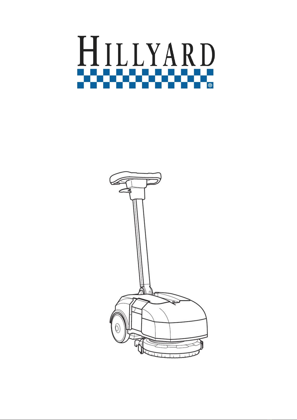
3.2.2 The Display doesn’t switch ON
1. Check the battery
voltage V≥33
YES ⇒Point 2
NO ⇒Replace the
battery
2. Check the voltage on
the connector J2 V≥33
YES ⇒Point 3
NO ⇒Replace the
cables
3. Check the voltage
J6-Pink / J2-Black V≥33
YES ⇒Point 4
NO ⇒Replace the
main card
4. Check the voltage
J6-Pink / J2-Black V≥33
YES ⇒Point 5
NO ⇒Replace the
cables
5.
Push the main switch
and check the voltage
J6-White / J2-Black
V≥33
YES ⇒Point 6
NO ⇒Replace the
switch
6. Check the voltage
J6-White / J2-Black V≥33
YES ⇒Point 7
NO ⇒Replace the
cables
7.
On the Handle card,
check the voltage on
the connector J4
Yellow & Green
V≥33 YES ⇒Point 8
NO ⇒Point 10
14

8.
On the Handle card,
check the voltage on
the connector J4
Yellow & Brown
V≥1YES ⇒Point 9
NO ⇒Point 11
9.
On the Handle card,
check the voltage on
the connector J4
Yellow & White
V≥1
YES ⇒Replace the
handle card
NO ⇒Point 12
10.
On the Main card,
check the voltage on
the connector J4
Yellow & Green
V≥33
YES ⇒Replace the
cables
NO ⇒Replace the
main card
11.
On the Main card,
check the voltage on
the connector J4
Yellow & Brown
V≥1
YES ⇒Replace the
cables
NO ⇒Replace the
main card
12.
On the Main card,
check the voltage on
the connector J4
Yellow & White
V≥1
YES ⇒Replace the
cables
NO ⇒Replace the
main card
3.2.3 The battery doesn’t work
1. Check the battery
voltage V≥33
YES ⇒Perform a
complete
charge cy-
cle.
NO ⇒Replace the
battery
15
3.2.4 The Display doesn’t show the battery level
All the other devices of the machine are functioning properly
1. Check the voltage
J5-Gray / J2-Black V≥1YES ⇒Point 2
NO ⇒Point 3
2. Check the voltage
J5-Violet / J2-Black V≥1
YES ⇒Replace the
main card
NO ⇒Point 4
3. Check the battery
voltage V≥1
YES ⇒Replace the
cables
NO ⇒Replace the
battery
4. Check the battery
voltage V≥1
YES ⇒Replace the
cables
NO ⇒Replace the
battery
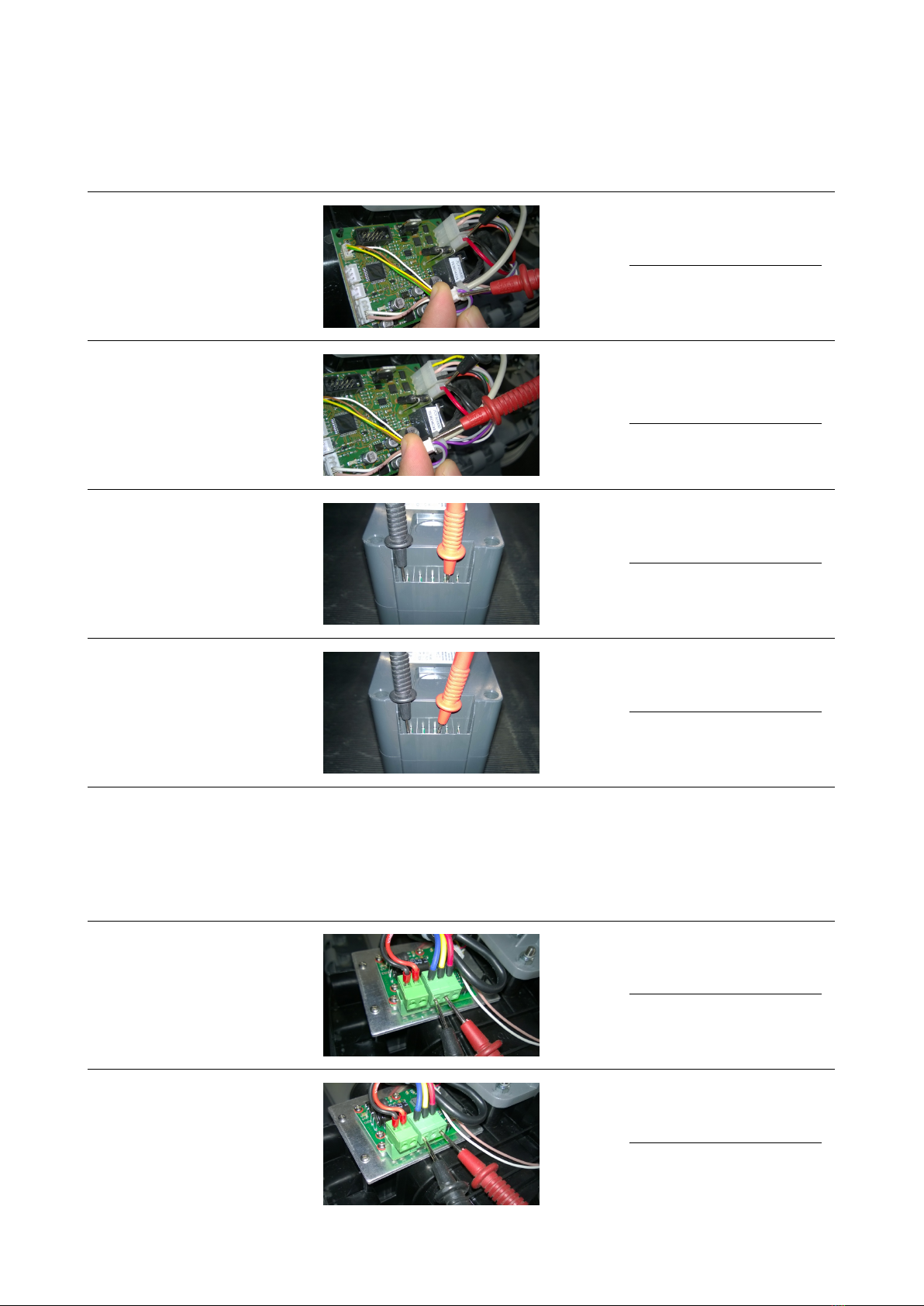
3.2.5 The brush Motor doesn’t work
All the other devices of the machine are functioning properly
1.
Check the voltage in
AC on the connector Y
Blue & Yellow (with
running machine)
V≥25 YES ⇒Point 2
NO ⇒Point 4
2.
Check the voltage in
AC on the connector Y
Blue & Red (with
running machine)
V≥25 YES ⇒Point 3
NO ⇒Point 4
16
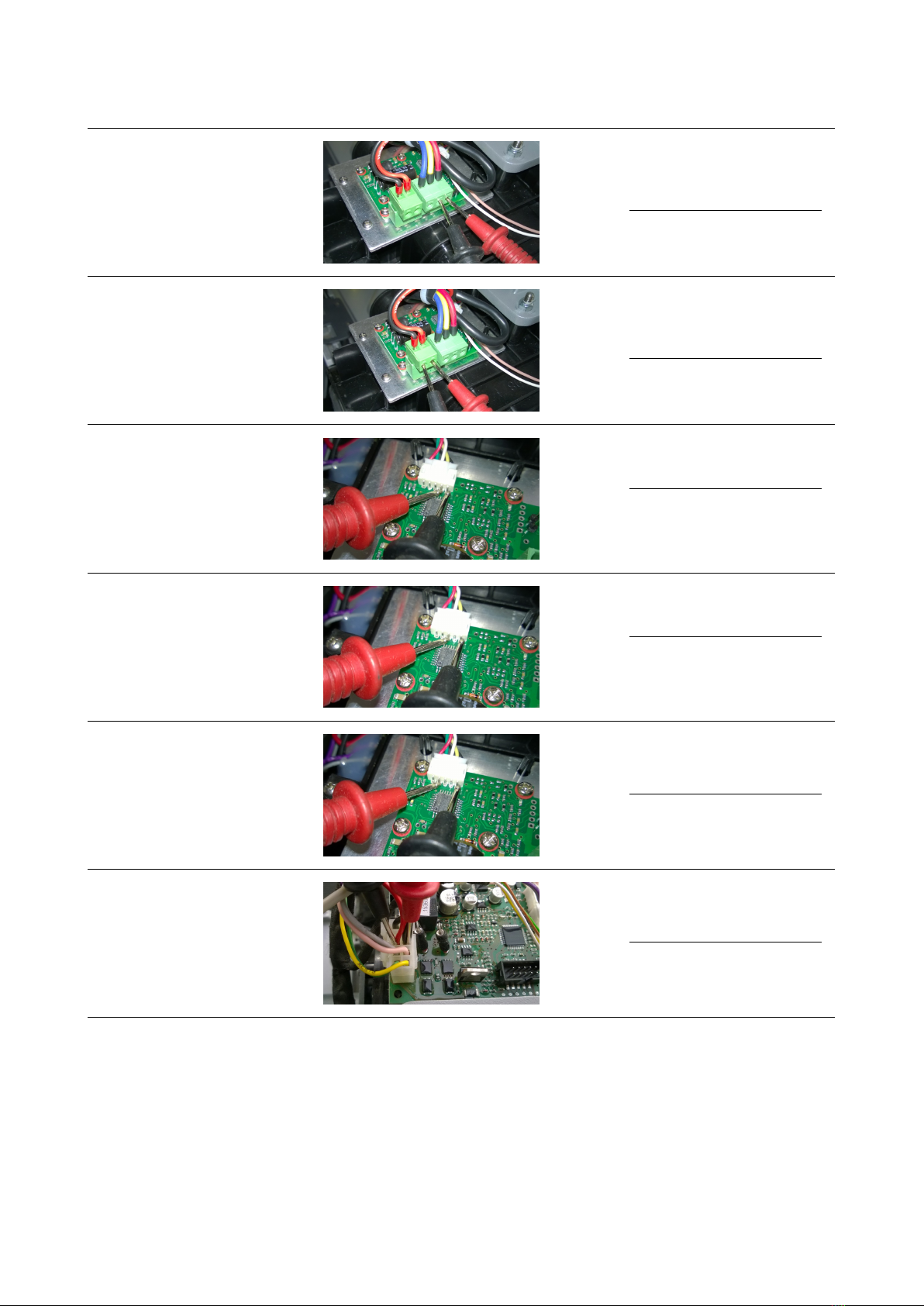
3.
Check the voltage in
AC on the connector Y
Yellow & Red (with
running machine)
V≥25
YES ⇒Replace the
motor
NO ⇒Point 4
4.
Check the voltage
on the connector X
Red & Black (with
running machine)
V≥33
YES ⇒Replace the
motor card
NO ⇒Point 5
5.
Check the voltage
on the connector W
Black & Yellow (with
running machine)
V≥0
YES ⇒Point 6
NO ⇒Replace the
motor
6.
Check the voltage
on the connector W
Black & White (with
running machine)
V≥0
YES ⇒Point 7
NO ⇒Replace the
motor
7.
Check the voltage
on the connector W
Black & Green (with
running machine)
V≥0
YES ⇒Replace the
motor card
NO ⇒Replace the
motor
8.
Check the voltage
on the connector J1
Red & Black (with
running machine)
V≥33
YES ⇒Replace the
cables
NO ⇒Replace the
main card
17
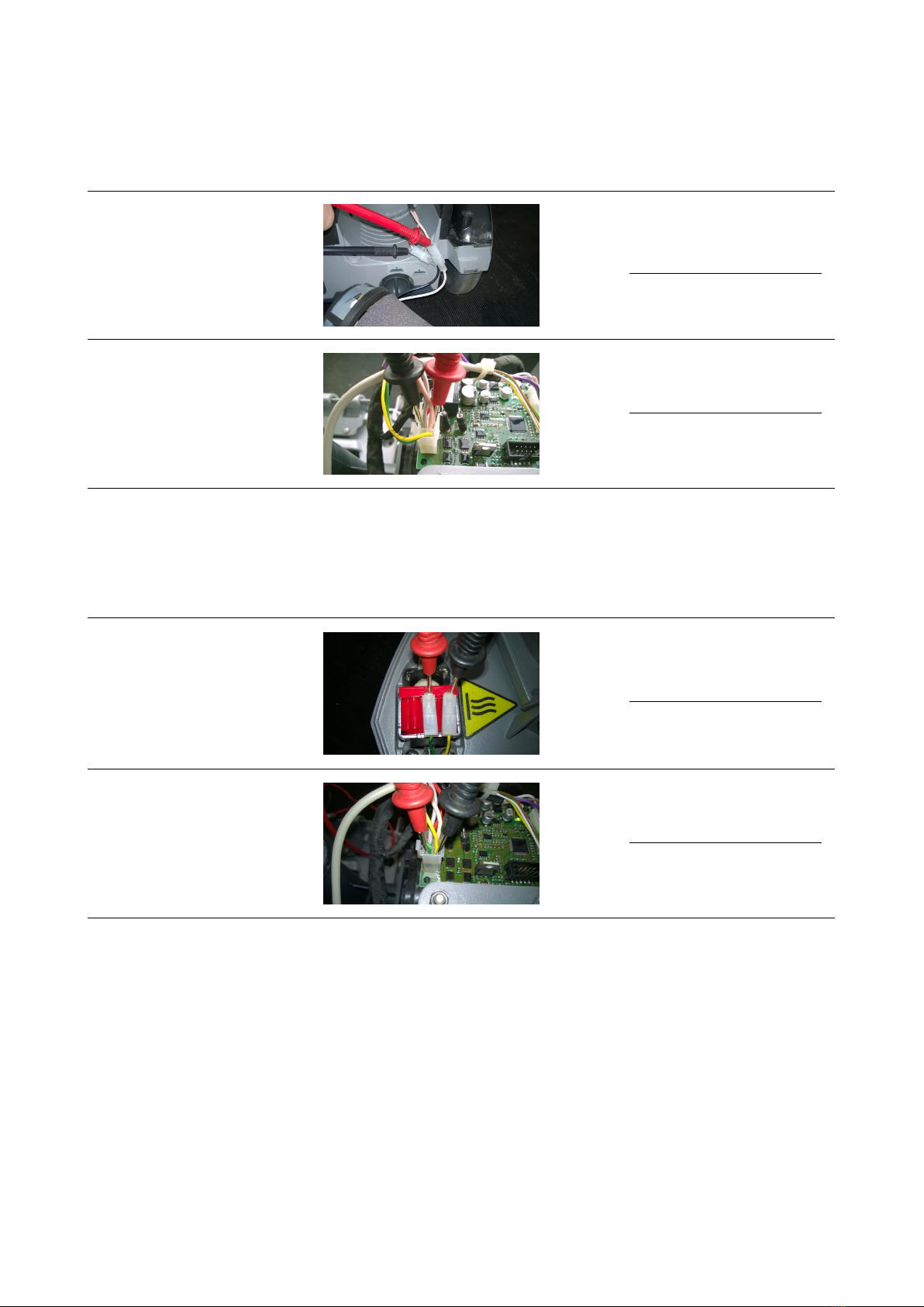
3.2.6 The suction Motor doesn’t work
All the other devices of the machine are functioning properly
1.
Check the voltage on
the faston (with
running machine)
V≥33
YES ⇒Replace the
motor
NO ⇒Point 2
2.
Check the voltage on
the connector J1
Gray & Pink (with
running machine)
V≥33
YES ⇒Replace the
cables
NO ⇒Replace the
main card
3.2.7 The Pump doesn’t work
All the other devices of the machine are functioning properly
1.
Check the voltage in
AC on the Pump’s
connectors, Don’t
disconnect the
connectors from the
pump (with running
machine)
V≥8
YES ⇒Replace the
pump
NO ⇒Point 2
2.
Check the voltage in
AC on the connector
J1 Green & Yellow
(with running
machine)
V≥36
YES ⇒Replace the
cables
NO ⇒Replace the
main card
18

Chapter 4
Disassembling Procedures
WARNING:BEFORE TO PERFORM ANY OPERATION DESCRIBED BELOW VERIFY THAT
THE MACHINE TANKS ARE COMPLETELY EMPTY,THE MACHINE HAS TO BE TURNED OFF.
REMOVE THE BATTERY FROM THE MACHINE. AT LAST,VERIFY THAT THE MACHINE IS
IN A TOTALLY SAFE CONDITION.
19

4.1 Electrical Installation
•Put the machine in safe conditions.
•Turn the handlebar forward in hori-
zontal position.
•Separate the lower casing of the
handlebar from the upper casing by
unscrewing the lower screws.
•Disconnect the connecting cable
from the control card and release the
cable from the fastening clamp.
•Remove the screws that secure the
Handlebar Control Card to the up-
per casing and remove the card.
•Remove the lifting handle from the
handlebar stem by unscrewing the
screws (see fig. 4.1.0-1).
•Release the lock levers of the tanks,
and remove them (see fig. 4.1.0-2).
4.1.0-1 4.1.0-2
•Lay the machine on its side, and
loosen the lower screws of the Up-
per Carter, near the wheels and the
On/Off button.
•Reposition the machine and remove
the upper screws from the front part
of the Upper Carter.
20
Other manuals for TRIDENT XM13SC
1
Table of contents
Other Hillyard Floor Machine manuals

Hillyard
Hillyard Trident BU1500 User manual

Hillyard
Hillyard TRIDENT T26SC PLUS User manual

Hillyard
Hillyard Trident EX8 User manual

Hillyard
Hillyard TRIDENT EX7 User manual

Hillyard
Hillyard TRIDENT EX12 User manual

Hillyard
Hillyard TRIDENT EX20 User manual

Hillyard
Hillyard TRIDENT T26 SC PLUS User manual
Popular Floor Machine manuals by other brands


Nilfisk-Advance
Nilfisk-Advance Hydro-Retriever 2052 Instructions for use

Superabrasive
Superabrasive Lavina 32 Pro user manual

Tennant
Tennant 355E Operator's manual

Kärcher
Kärcher BDS 43/180 C manual

Powr-Flite
Powr-Flite PEB Operator's manual & parts list

Tornado
Tornado 97564 Operation & maintenance manual