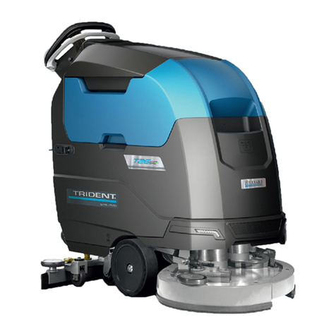
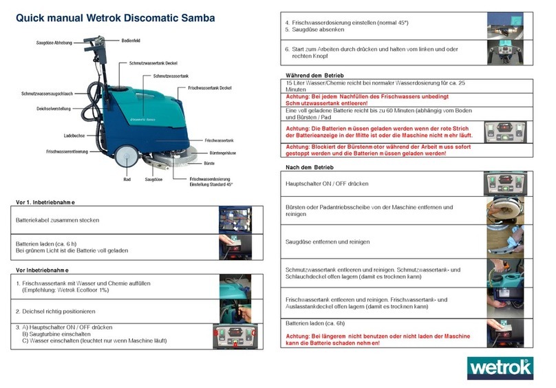
Hillyard TRIDENT T26SC PLUS User manual

SERVICE MANUAL
TRIDENT T26SC PLUS
Version: AB
Date: November 7, 2018
Document Number:10077484

Contents
I Product Introduction 4
1 Serial Number and Technical Support 5
1.1 The Serial Tag ................................. 5
1.2 Serial Tag location ............................... 5
2 Main Technical Features 6
II Anomalies Resolution Guide 8
3 Trouble-shooting for the most common anomalies. 9
3.1 Electrical system: what to do if. . . ...................... 9
3.2 Mechanical scrubbing system: what to do if. . . .............. 12
3.3 Drying system: what to do if. . . ....................... 13
3.4 Frame and traction system: what to do if. . . ................ 15
3.5 Solution delivery system: what to do if. . . ................. 16
3.6 Alarm & Warning Table ............................ 17
4 Disassembling Procedures 20
4.1 Electrical Installation ............................. 21
4.2 Mechanical Friction System ......................... 22
4.3 Drying System ................................. 23
4.4 Frame and Traction System ......................... 25
4.5 Solution Delivery System ........................... 26
III Machine Description 28
5 Electrical System 29
5.1 Description T26SC PLUS ........................... 29
5.2 Location of Electrical components ...................... 30
5.3 Adjustments .................................. 36
5.4 Maintenance and Checks ........................... 38
5.5 Programming .................................. 39
6 Mechanical Rubbing System 46
6.1 Description ................................... 46
6.2 Adjustments .................................. 47
6.3 Maintenance and checks ........................... 48
2

7 Drying System 50
7.1 Structure .................................... 50
7.2 Description ................................... 50
7.3 Adjustments .................................. 51
7.4 Maintenance and Checks ........................... 52
8 Machine Frame and Traction System 55
8.1 Structure .................................... 55
8.2 Description ................................... 55
8.3 Maintenance and Checks ........................... 56
9 Cleaning Solution Supply System 57
9.1 Structure .................................... 57
9.2 Description ................................... 57
9.3 Maintenance and Checks ........................... 58
10 Consumable & Recommended Spare Parts 59
10.1Consumable Spare Parts ........................... 59
10.2Recommended Spare Parts .......................... 60
3

Part I
Product Introduction
4

Chapter 1
Serial Number and Technical Support
1.1 The Serial Tag
1.2 Serial Tag location
To have access to the Serial Tag is necessary to lift the recovery tank.
The Serial Number is an extremely important information which has to be provided
each time a Technical Support is required or is necessary to buy spare parts or
accessories. The serial number is the only way to identify the machine by model,
production date type equipments in general.
5

Chapter 2
Main Technical Features
Technical Data
TECHNICAL DESCRIPTION U/M T26SC PLUS
Traction Motor (Voltage - Nominal Power) V-W 24-180
Ramp Gradient in transport1% 10
Max speed in transport (Default) mph 2.2
Supply/Traction V 24-Aut.
Vacuum Motor (Voltage - Nominal Power) V-W 24-420
Vacuum motor Stages Nr 2
Vacuum group suction mbar 91,4
Steering diameter in 77
Suggested battery (Voltage - Power) V-AhC5 12 - 110
Maximum batteries weight lb 180
Battery compartment dimensions
(Width-Length-Height)
in 19-14-10
Solution Tank gal 16
Recovery Tank gal 17
Usage temperature (Min - Max) °F 32-110
Sound pressure level (ISO 11201) LpA dB (A) ≤70
Hand vibration level (ISO 5349) ft
s2≤3,60
1Machine + batteries + full solution tank
6

Technical Data T26SC PLUS
TECHNICAL DESCRIPTION U/M T26SC PLUS
Working width in 25
Working capacity, up to f t2
h25200
Total Power W 1390
Brushdeck Motor
(Number - Voltage - Nominal Power)
Nr-V-W 2-24-400
Disc Brushes (Number - External Ø) Nr-Øin 2-13
Brushes revolutions rpm 140
Max Weigth on brush lb 120
Machine Length in 51
Machine Height in 43
Machine Width (without squeegee) in 26
Machine Width (with squeegee) in 31
Weights and Pressures T26SC PLUS2
TECHNICAL DESCRIPTION U/M T26SC PLUS
Machine Weight (empty and without batteries) lb 152
Machine Gross Weight, work condition
(machine + batteries + water)
lb 360
Weight on front right wheel lb 114 ÷163
Pressure made by the front right wheel lb
in282 ÷111
Weight on front left wheel lb 101 ÷153
Pressure made by the front left wheel lb
in277 ÷121
Weight on rear right wheel lb 23 ÷98
Pressure made by the rear right wheel lb
in2234 ÷734
Weight on rear left wheel lb 23 ÷98
Pressure made by the rear left wheel lb
in2234 ÷734
2Weight and Pressures depends on how much water there is in the tanks and on what type of battery the
machine fits.
7

Part II
Anomalies Resolution Guide
8

Chapter 3
Trouble-shooting for the most common
anomalies.
3.1 Electrical system: what to do if. . .
The machine doesn’t switch on
1. The key is in position 0 ⇒Rotate the key in position I.
2. The key microswitch is not properly
connected
⇒Restore the proper connections.
3. The key microswitch doesn’t work ⇒Replace the key microswitch (see section
4.1.1 at page 21).
4. The batteries don’t work properly ⇒Refer to the proper section (see section
3.1 at page 10).
9

The batteries don’t work properly
1. The batteries are not properly con-
nected
⇒Connect properly the loop cable and
the power supply cables.
2. Battery are discharged ⇒Perform a complete charge cycle.
3. Battery terminal are oxidized ⇒Disconnect the batteries, clean the
batteries terminals and reconnect
properly the batteries.
4. With the machine in working con-
ditions one battery has a voltage
lower (difference higher than 2 V)
than the other ones
⇒Replace the battery with lower volt-
age.
5. The fuse on the loop wire is dam-
aged
⇒Check for possible short circuits, If
not present replace the loop wire.
6. The power wires are damaged ⇒Replace the damaged wires.
7. The battery charger is not properly
adjusted
⇒Adjust properly the battery charger
(see section 5.3.1 at page 36).
8. The battery charger doesn’t work ⇒Check the proper section (see section 3.1
at page 10).
The battery charger doesn’t work
1. The battery charger is not con-
nected to the power supply
⇒Connect the charger to a supplied
electric socket.
2. The battery charger is not con-
nected to the batteries
⇒Connect the charger to the batteries.
3. The battery charger has one or
more lights (or LEDs) blinking con-
tinuously
⇒The battery charger is in error con-
ditions, verify the alarm tables and
solve the issue by following the re-
lated instructions (see section 5.3.1 at page
36).
4. The battery charger is properly con-
nected but it doesn’t switch on
⇒Replace the battery charger.
10

The display shows an alarm message
1. The display shows an alarm mes-
sage
⇒Check what alarm message is
shown and solve the related issue
by following the proper instructions
(see section 3.6 at page 17).
The machine has a very limited working autonomy
1. The batteries connections are oxi-
dized
⇒Unplug the connection wires, wash
the wire connections with water and
reconnect them protecting them with
grease.
2. When the machine is working a bat-
tery voltage is lower and lower than
the other batteries (The difference is
bigger than 2V)
⇒Replace the battery with the lower
voltage.
3. The battery charger is not properly
adjusted
⇒Verify the type of battery in use and
adjust the battery charger properly
following the instructions (see section
5.3.1 at page 36).
4. The BDI (Battery Discharge Indica-
tor) is not properly adjusted
⇒Verify the type of battery used on
the machine and adjust properly the
BDI (see section 5.5.1 at page 39).
5. Batteries have been working for
several cycles
⇒Replace the batteries.
11

3.2 Mechanical scrubbing system: what to do if. . .
The machine doesn’t clean well
1. The machine is switched off ⇒Switch on the machine.
2. The machine doesn’t switch on ⇒Refer to the proper section (see section
3.1 at page 9).
3. The display shows an alarm mes-
sage
⇒Check what alarm message is
shown and solve the related issue
by following the proper instructions
(see section 3.6 at page 17).
4. The ”ECO” switch is not pressed ⇒Press the ”ECO” switch.
5. The safety switch doesn’t work ⇒Replace the safety switch (see section
4.1.1 at page 21).
6. The brush deck motor is not sup-
plied
⇒Verify the motor connections.
7. The carbon brushes are worn out ⇒Replace the carbon brushes (see section
6.3.1 at page 48).
8. The brush motor is supplied but it
doesn’t work
⇒Replace the motor (see section 4.2.3 at page
23).
9. The brush rotates in opposite way ⇒Check the motor connections.
10. The brush deck is lifted from the
floor
⇒Lower the brushdeck to the floor.
11. The brush is not properly engaged ⇒Release and engage properly the
brush.
12. The solution flow rate is not correct
or not enough
⇒Refer to the proper section (see section
3.5 at page 16).
12

3.3 Drying system: what to do if. . .
The machine doesn’t dry well
1. The machine is switched off ⇒Switch on the machine.
2. The machine doesn’t switch on ⇒Refer to the proper section (see section
3.1 at page 9).
3. The recovery tank is full ⇒Empty the recovery tank following
the proper procedure.
4. The vacuum motor doesn’t switch
on
⇒Refer to the proper section (see section
3.3 at page 14).
5. The machine is in ”ECO” mode ⇒Set up the machine as per standard
configuration.
6. The squeegee is lifted up from the
floor
⇒Lower down the squeegee.
7. The squeegee rubber blades are
worn out or broken
⇒Rotate or replace the squeegee rub-
ber blades.
8. The squeegee is not properly ad-
justed
⇒Adjust the squeegee properly follow-
ing the proper procedure (see section 7.3.1
at page 51).
9. The squeegee vacuum chamber or
adapter is stuck or dirty
⇒Clean the squeegee vacuum cham-
ber (see section 7.4.1 at page 52).
10. The vacuum hose is stuck or bro-
ken
⇒Clean or replace the vacuum hose.
11. The vacuum hose is not properly
fitted in
⇒Connect the vacuum hose properly.
12. The intake manifold is stuck or bro-
ken
⇒Clean or replace the intake manifold
(see section 7.4.6 at page 53).
13. The intake manifold is not properly
connected
⇒Connect the intake manifold prop-
erly.
14. The vacuum filter is dirty or stuck ⇒Disassemble and clean the vacuum
filter.
15. The vacuum cover is not well posi-
tioned or is missing
⇒Position properly the vacuum cover.
16. The vacuum cover gasket doesn’t
adhere properly
⇒Replace the vacuum cover gasket.
13

The vacuum motor doesn’t work properly
1. The vacuum motor is switched off ⇒Switch on the vacuum motor.
2. The vacuum motor is not powered
properly
⇒Check the power connections on the
vacuum motor.
3. The display shows an alarm mes-
sage
⇒Check what alarm message is
shown and solve the related issue
by following the proper instructions
(see section 3.6 at page 17).
4. The vacuum motor carbon brushes
are worn out
⇒Replace the vacuum motor carbon
brushes (see section 7.4.7 at page 53).
5. The vacuum motor is supplied but
it doesn’t work
⇒Replace the vacuum motor (see section
4.3.7 at page 25).
14

3.4 Frame and traction system: what to do if. . .
The traction motor doesn’t work properly
1. The machine is switched off ⇒Switch on the machine.
2. The machine doesn’t switch on ⇒Check the proper section (see section 3.1
at page 9).
3. The display shows an alarm mes-
sage
⇒Check what alarm message is
shown and solve the related issue
by following the proper instructions
(see section 3.6 at page 17).
4. The electro brake doesn’t disengage ⇒Check the electro brake connections.
5. The safety lever is not pressed ⇒Push the safety lever.
6. The safety microswitch is not prop-
erly connected
⇒Restore the proper connection to the
safety microswitch.
7. The safety microswitch doesn’t
work
⇒Replace the safety microswitch.
8. The speed adjuster doesn’t work ⇒Replace the speed adjuster.
9. The motor is not supplied ⇒Verify the motor connections.
10. The traction motor carbon brushes
are worn out
⇒Replace the carbon brushes (see section
8.3.2 at page 56).
11. The traction motor is supplied but
it doesn’t work
⇒Replace the traction motor (see section
4.4.2 at page 26).
15

3.5 Solution delivery system: what to do if. . .
The delivered solution is not correct or not enough
1. The machine is switched off ⇒Switch on the machine.
2. The machine doesn’t switch on ⇒Refer to the proper section (see section
3.1 at page 9).
3. The solution tank is empty ⇒Fill up the solution tank.
4. The water valve for the solution flow
adjustment is completely closed
⇒Open the water valve to the desired
position.
5. The water flow is adjusted at mini-
mum
⇒Increase the water flow adjustment.
6. The solenoid valve doesn’t work ⇒Check the solenoid valve connec-
tions and, if necessary, replace it (see
section 4.5.3 at page 27).
7. The solution filter is stuck ⇒Clean the solution filter.
8. The display shows an alarm mes-
sage
⇒Check what alarm message is
shown and solve the related issue
by following the proper instructions
(see section 3.6 at page 17).
9. The detergent doesn’t fit the type of
dirt
⇒Replace the detergent with a proper
one.
16

3.6 Alarm & Warning Table
3.6.1 General Alarms
Id Alarm Meaning Solution
AL 1 General EEPROM failure Detected an Error in the internal memory of the card. Turn off and on
again. If the error persists, replace the card.
AL 2 General Key-off failure Return on the key signal. Turn off the machine, wait at least 2 seconds,
and then turn it on again. If the problem persists, replace the key block.
AL 3 General Undervoltage Detected supply voltage less than 15V (even instantly). Check the bat-
teries and their connection and the connection between the batteries and
the main card. If the error persists, replace the card.
AL 4 General Overvoltage Detected supply voltage more than 35V (even instantly). Check the bat-
teries and their connection and the connection between the batteries and
the main card. If the error persists, replace the card.
AL 5 General Battery not connected Detected no voltage on the battery poles but present on the key input
(disabled for this machine).
AL 6 General Keyboard
Communication
No communication between display and main board. Check the connec-
tion between the cards. If the problem persists, replace the main card or
the display card.
AL 7 General Communication FFM Lack of communication between the BB and the main card. Check the
connection between the cards. If the problem persists, replace the main
card or the BB.
AL 8 General Communication 1 Internal error in the main card BUS data, turn off and on again. If the
problem persists, replace the main card.
AL 9 General Communication 2 Internal error in the main card BUS data, turn off and on again. If the
problem persists, replace the main card.
AL 10 General Insert Tag One of the enabled TAGs is not inserted. Enter one of the enabled TAGs
in the Slot.
AL 11 General Invalid Tag The inserted TAG is not enabled. Enter one of the enabled TAGs in the
Slot.
AL 12 General Update in
progress. . .
The machine is updating the parameter list. Wait for the end of the oper-
ation.
AL 13 General Restart
the Machine
After updating the parameters (AL 12) indicates that is necessary to
restart the machine.
AL 14 General Recovery Full The recovery tank is full, drain it.
17

3.6.2 Function Alarms
Id Alarm Meaning Solution
AL 41 Function Overtemperature The temperature of the functions power mosfets exceeds 90°C. Switch off
the machine, wait for the cooling and then switch on again.
AL 42 Function Powerstage failure Verify the machine model setting, turn it off and on again. If the problem
persists, replace the main card.
AL 43 Function Main fuse failure Check the Function fuse. If the problem persists, replace the main card.
AL 44 Function Main relay failure Replace the main card.
AL 45 Function Main relay failure CC Replace the main card.
AL 46 Function Overcurrent brush
motor
Brushes Short Circuit. Check the connections, if the problem persists,
replace the main card.
AL 47 Function Overcurrent vacuum
motor
Vacuum Short Circuit. Check the connections, if the problem persists,
replace the main card.
AL 48 Function Overcurrent pump Pumps Short Circuit. Check the connections, if the problem persists,
replace the main card.
AL 49 Function Brush motor
Ammeter
Overcurrent of the Brush Motor.
AL 50 Function Brushes motor 2
Ammeter
Overcurrent of the Right Brush Motor (MMg Disc) or Rear (MMG Cylin-
drical)
AL 51 Function Brushes motor 3
Ammeter
Overcurrent of the Right Brush Motor / Motors
AL 52 Function Vacuum motor
Ammeter
Overcurrent of the Vacuum Motor.
AL 53 Function Vacuum motor 2
Ammeter
Overcurrent of the second Vacuum Motor
3.6.3 Function Alarms
Id Alarm Meaning Solution
AL 60 Function Actuator1: timeout Only with external limit switches, if the actuator does not come into po-
sition within a preset time (disabled for this machine).
AL 61 Function Actuator 1 Ammeter Overcurrent of the Brushdeck Actuator.
AL 62 Function Actuator 1
Overcurrent
Brush Actuator Short Circuit. Check the connections, if the problem
persists, replace the main card.
AL 63 Function Actuator1:
endsw failure
When switch-on the machine, 1 microswitch is open: check the scrub-
deck microswitches and its cables, and the scrubdeck position.
AL 64 Function Actuator2: timeout Only with external limit switches, if the actuator does not come into po-
sition within a preset time (disabled for this machine).
AL 65 Function Actuator2: Ammeter Overcurrent of the Side brushdeck/s Actuator/s.
AL 66 Function Actuator2:
Overcurrent
Side Brushes Actuator Short Circuit. Check the connections, if the prob-
lem persists, replace the main card.
AL 67 Function Actuator2:
endsw failure
When switch-on the machine, 1 microswitch is open: check the scrub-
deck microswitches and its cables, and the scrubdeck position.
AL 68 Function Actuator3: timeout Only with external limit switches, if the actuator does not come into po-
sition within a preset time (disabled for this machine).
AL 69 Function Actuator 3 Ammeter Overcurrent of the Squeegee Actuator.
AL 70 Function Actuator 3
Overcurrent
Squeegee Actuator Short Circuit. Check the connections, if the problem
persists, replace the main card.
AL 71 Function Actuator3:
endsw failure
When switch-on the machine, 1 microswitch is open: check the scrub-
deck microswitches and its cables, and the scrubdeck position.
18

3.6.4 Traction Alarms
Id Alarm Meaning Solution
AL 80 Traction Overtemperature The temperature of the traction power mosfets exceeds 90°C. Switch off
the machine, wait for the cooling and then switch on again.
AL 81 Traction Powerstage failure Turn it off and on again. If the problem persists, replace the main card.
AL 82 Traction Main fuse failure Check the Traction fuse. If the problem persists, replace the main card.
AL 83 Traction Main relay failure Replace the main card.
AL 84 Traction Main relay failure CC Replace the main card.
AL 85 Traction Traction Overcurrent Traction Motor Short Circuit. Check the connections, if the problem per-
sists, replace the main card.
AL 86 Traction Traction
Ammeter
Overcurrent of the Traction Motor.
AL 87 Traction Motor data reading Abnormal traction motor Output current. Check the traction motor and
its connections. If the problem persists, replace the main card.
AL 88 Traction Electrobrake failure No current on the electrobrake output. Verify that the electrode is acti-
vated, check its connections. If the problem persists, replace the electro-
brake.
AL 89 Traction Potentiometer adjust-
ment issue
Abnormal Potentiometer Output voltage. Check the potentiometer and
its connections. If the problem persists, replace the potentiometer.
AL 90 Traction Lever pressed The lever is pressed while the key is switching on. Check the safety
microswitch and its connections. If the problem persists, replace the
microswitch.
AL 91 Traction Encoder failure The encoder provides non-coherent information. Verify the Encoder and
its Connections. If the problem persists, replace the Encoder.
19

Chapter 4
Disassembling Procedures
WARNING:BEFORE TO PERFORM ANY OPERATION DESCRIBED BELOW VERIFY THAT
THE MACHINE TANKS ARE COMPLETELY EMPTY,THE MACHINE HAS TO BE TURNED
OFF. DISCONNECT THE BATTERIES AND REMOVE THEM FROM THE MACHINE. AT LAST,
VERIFY THAT THE PARKING BRAKE IS ENGAGED AND THE MACHINE IS IN A TOTALLY
SAFE CONDITION.
20
Table of contents
Other Hillyard Floor Machine manuals
Popular Floor Machine manuals by other brands
Cleaning Machines
Cleaning Machines KRUGER KF43E manual
Fimap
Fimap MMg base Inspection manual
Tennant
Tennant M17 Series Instruction bulletin
Windsor
Windsor MERIT1500 operating instructions
Nilfisk-Advance
Nilfisk-Advance Whirlamatic 2700 BHS 7014 Service manual
ROOTS
ROOTS RootsScrub RB 800 Operator's manual

Lavorwash
Lavorwash Lavor Pro FREE EVO 50E manual
Sweepster
Sweepster WLA 213 Series Operator and parts manual
Nilfisk-Advance
Nilfisk-Advance AquaRide 56314009 Instructions for use
Kärcher
Kärcher CV 38/2 user manual

Nilfisk-Advance
Nilfisk-Advance Kent SelectLine 17TS Operator's manual
Wetrok
Wetrok Duomatic Esprit manual
