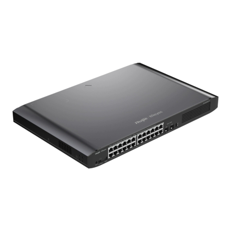
HiLook NS-0106P-35 Series User manual

4-Port or 8-Port Unmanaged PoE Switch
Quick Start Guide
UD22316B

Legal Informaon
©2020 Hangzhou Hikvision Digital Technology Co., Ltd.
About this Manual
Pictures, charts, images and all other informaon hereinaer are
for descripon and explanaon only. The informaon contained
in the Manual is subject to change, without noce, due to
rmware updates or other reasons. Please nd the latest version
in the company website ( hps://www.hikvision.com/ ). Please
use this user manual under the guidance of professionals.
Trademarks
and other Hikvision's trademarks
and logos are the properes of Hikvision in various jurisdicons.
Other trademarks and logos menoned below are the properes
of their respecve owners.
Disclaimer
TO THE MAXIMUM EXTENT PERMITTED BY APPLICABLE LAW, THIS
MANUAL AND THE PRODUCT DESCRIBED, WITH ITS HARDWARE,
SOFTWARE AND FIRMWARE, ARE PROVIDED “AS IS” AND “WITH
ALL FAULTS AND ERRORS”. HIKVISION MAKES NO WARRANTIES,
EXPRESS OR IMPLIED, INCLUDING WITHOUT LIMITATION,
MERCHANTABILITY, SATISFACTORY QUALITY, OR FITNESS FOR A
PARTICULAR PURPOSE. THE USE OF THE PRODUCT BY YOU IS AT
YOUR OWN RISK. IN NO EVENT WILL HIKVISION BE LIABLE TO YOU
FOR ANY SPECIAL, CONSEQUENTIAL, INCIDENTAL, OR INDIRECT
DAMAGES, INCLUDING, AMONG OTHERS, DAMAGES FOR LOSS OF
BUSINESS PROFITS, BUSINESS INTERRUPTION, OR LOSS OF DATA,
CORRUPTION OF SYSTEMS, OR LOSS OF DOCUMENTATION,
WHETHER BASED ON BREACH OF CONTRACT, TORT (INCLUDING
NEGLIGENCE), PRODUCT LIABILITY, OR OTHERWISE, IN
CONNECTION WITH THE USE OF THE PRODUCT, EVEN IF
HIKVISION HAS BEEN ADVISED OF THE POSSIBILITY OF SUCH
DAMAGES OR LOSS.
YOU ACKNOWLEDGE THAT THE NATURE OF THE INTERNET
PROVIDES FOR INHERENT SECURITY RISKS, AND HIKVISION SHALL
NOT TAKE ANY RESPONSIBILITIES FOR ABNORMAL OPERATION,
PRIVACY LEAKAGE OR OTHER DAMAGES RESULTING FROM
CYBER-ATTACK, HACKER ATTACK, VIRUS INFECTION, OR OTHER
INTERNET SECURITY RISKS; HOWEVER, HIKVISION WILL PROVIDE
TIMELY TECHNICAL SUPPORT IF REQUIRED.
YOU AGREE TO USE THIS PRODUCT IN COMPLIANCE WITH ALL
APPLICABLE LAWS, AND YOU ARE SOLELY RESPONSIBLE FOR
ENSURING THAT YOUR USE CONFORMS TO THE APPLICABLE LAW.
ESPECIALLY, YOU ARE RESPONSIBLE, FOR USING THIS PRODUCT IN
A MANNER THAT DOES NOT INFRINGE ON THE RIGHTS OF THIRD
PARTIES, INCLUDING WITHOUT LIMITATION, RIGHTS OF
PUBLICITY, INTELLECTUAL PROPERTY RIGHTS, OR DATA
PROTECTION AND OTHER PRIVACY RIGHTS. YOU SHALL NOT USE
i

THIS PRODUCT FOR ANY PROHIBITED END-USES, INCLUDING THE
DEVELOPMENT OR PRODUCTION OF WEAPONS OF MASS
DESTRUCTION, THE DEVELOPMENT OR PRODUCTION OF
CHEMICAL OR BIOLOGICAL WEAPONS, ANY ACTIVITIES IN THE
CONTEXT RELATED TO ANY NUCLEAR EXPLOSIVE OR UNSAFE
NUCLEAR FUEL-CYCLE, OR IN SUPPORT OF HUMAN RIGHTS
ABUSES.
IN THE EVENT OF ANY CONFLICTS BETWEEN THIS MANUAL AND
THE APPLICABLE LAW, THE LATER PREVAILS.
ii

Preface
Applicable Models
This manual is applicable to NS-0106P-35 and NS-0310P-60
series switches.
Symbol Convenons
The symbols that may be found in this document are dened as
follows.
Symbol Descripon
Danger Indicates a hazardous situaon which, if not avoided,
will or could result in death or serious injury.
Cauon
Indicates a potenally hazardous situaon which, if
not avoided, could result in equipment damage, data
loss, performance degradaon, or unexpected
results.
Note Provides addional informaon to emphasize or
supplement important points of the main text.
iv

Safety Instrucon
Danger
•The device must be connected to an earthed mains socket-
outlet.
•The socket-outlet shall be installed near the device and shall be
easily accessible.
• indicates hazardous live and the external wiring connected
to the terminals requires installaon by an instructed person.
•This is a class A product and may cause radio interference in
which case the user may be required to take adequate
measures.
Cauon
•In the use of the product, you must be in strict compliance with
the electrical safety regulaons of the naon and region.
•CAUTION: Double pole/Neutral fusing. Aer operaon of the
fuse, parts of the device that remain energized might represent
a hazard during servicing.
•The device has been designed, when required, modied for
connecon to an IT power distribuon system.
•Install the device according to the instrucons in this manual.
•To prevent injury, this device must be securely aached to the
rack in accordance with the installaon instrucons.
•This device is suitable for mounng on concrete or other non-
combusble surface only.
•Do not place any naked ame sources, such as lit candles, on
the device.
•Do not place any objects containing water or liquids on the
device. Prevent the device from water dropping or splashing.
•Keep some distance around the device for sucient
venlaon.
•The venlaon should not be impeded by covering the
venlaon openings with items, such as newspapers, table-
cloths, curtains, etc. The openings shall never be blocked by
placing the device on a bed, sofa, rug or other similar surface.
v

N 35 N 60
N 35 N 60
N 35
N 60
N 35
N 60

Indicator/Port Descripon
PoE-MAX Indicator
•Solid /Flashing: The output power of the switch
will reach the upper limit. The power supply may
be abnormal if more devices are connected.
•Unlit: The switch provides power supply to PD
normally.
PWR Indicator
•Solid: The switch is powered on normally.
•Unlit: No power supply connected or power
supply is abnormal.
LINK/ACT Indicator
•Solid: The port is connected.
•Flashing: The port is transming data.
•Unlit: The port is disconnected or connecon is
abnormal.
PoE Indicator
•Solid: The switch provides power supply to PD
normally.
•Unlit: The switch is disconnected to PD, or
provides power supply to PD abnormally.
PoE Port Used for other PD devices connecon via network
cables.
(Gigabit) RJ45 Port Used for devices connecon via network cables.
Grounding Terminal Used for connecng to the grounding cable to
protect the switch from lightning.
Power Supply Use the aached power cord to connect the switch
to socket.
DIP Switch
Support extend mode: Ports 1 to 4 of DS-3E0106P-
E/M and ports 1 to 8 of DS-3E0310P-E/M support
network transmission of up to 250 metres.
2 Installaon
Please select the appropriate installaon method according to
the actual needs.
Before You Start
•Keep the room well-venlated.
•Keep at least 10 cm distance around the device for heat
dissipaon.
2.1 Desk-Mounted Installaon
Place the device on the desk.
2.2 Wall-Mounted Installaon
Steps
1. Check the distance between the two hanging holes on the rear
cover of the device.
2. Insert two M4 screws into the wall.
2

Note
•Please prepare two M4 screws.
•Ensure that the distance between the two screws equals
that between the two hanging holes.
•Set aside at least 4 mm screws outside the wall.
3. Align the hanging holes with screws, and hang the device on
the screws.
Figure 2-1 Wall-Mounted Installaon
3 Grounding
3.1 Connecng the Grounding Cable
Grounding is used to quickly release overvoltage and overcurrent
induced by lightening for switch, and to protect personal safety.
Select the appropriate grounding method according to your
needs.
3.1.1 With Grounding Bar
If a grounding bar is available at the installaon site, follow the
steps below.
Steps
1. Connect one end of the grounding cable to the binding post on
the grounding bar.
2. Connect the other end of the grounding cable to the grounding
terminal of the device and x the screw.
Figure 3-1 Grounding with Grounding Bar
3.1.2 Without Grounding Bar
If there is no grounding bar but the earth is nearby and the
grounding body is allowed to be buried, follow the steps below.
Steps
1. Bury an angle steel or steel pipe (≥ 0.5 m) into the mud land.
3

2. Weld one end of the grounding cable to the angle steel or steel
pipe and embalm the welding point via electroplang or
coang.
3. Connect the other end of the grounding cable to the grounding
terminal.
Figure 3-2 Grounding with Angle Steel
3.2 Connecng RJ45 Port
Use a network cable to connect the device to the RJ45 port of a
peer device such as network camera, NVR, switch, etc.
Figure 3-3 RJ45 Port Connecon
4 Powering on the Device
Please use the aached power cord in package to power on the
device.
Before powering your switch, make sure that:
•The operang power supply is compliant with rated input
standard.
•Port cables and grounding cables are correctly connected.
•If there is outdoor cabling, connect a lightning rod and
lightening arrester to the cable.
Cauon
PoE power supply line and strong wire cannot be wired together,
otherwise PD equipment or switch ports will be burnt.
4
This manual suits for next models
1
Table of contents

