hiltbrand DUNGS GGW A4 Series User manual

1 … 16
MC • Edition 04.18 • Nr. 239 364
EU-Konformitäts-
erklärung
Gebrauchs-
anleitung
EU-Declaration of
conformity
Instructions
Déclaration de
conformité EU
Notice
d’utilisation
Dichiarazione di
conformità EU
Istruzioni
di esercizio e
di montaggio
GGW...A4, GGW...A4-U, GGW...A4/2, GGW...
A4-U/2, GGW... / ...A4
Di erenzdruck-
wächter für Gas,
Luft, Rauch- und
Abgase
Doppeldruck-
wächter
Di erential pres-
sure switch for
gas, air, ue and
exhaust gases
Double pressure
switch
Pressostat di é-
rentiel pour gaz,
air, fumée et gaz
brûlés
Pressostat double
Pressostato dif-
ferenziale per
gas, aria, gas di
combustione e di
scarico
Pressostatodoppio
GGW...A4, GGW...A4-U, GGW...A4/2,
GGW...A4-U/2, GGW... / ...A4
# 239 364
2 … 16
MC • Edition 04.18 • Nr. 239 364
HR SRB BIH SK
EU-Konformitäts-
erklärung
EU-Declaration of
conformity
Déclaration de
conformité EU
Dichiarazione di
conformità EU
Dr.-Ing. Karl-Günther Dalsaß,
Geschäftsführer / Chief Operating Ocer
Directeur / Amministratore
Urbach, 2018-04-21
Produkt / Product
Produit / Prodotto GGW...A4, GGW...
A4-U, GGW...A4/2,
GGW...A4-U/2
GGW... / ...A4
Dierenzdruckwächter für Gas, Luft, Rauch- und Abgase
Dierential pressure switch for gas, air, ue and exhaust gases
Pressostat diérentiel pour gaz, air, fumée et gaz brûlés
Pressostato dierenziale per gas, aria, gas di combustione e di scarico
Doppeldruckwächter/Doublepressureswitch/Pressostatdouble /
Pressostato doppio
Hersteller / Manufacturer
Fabricant / Produttore Karl Dungs GmbH & Co. KG
Karl-Dungs-Platz 1
D-73660 Urbach, Germany
bescheinigt hiermit, dass die in die-
ser Übersicht genannten Produkte
einer EU-Baumusterprüfung un-
terzogen wurden und die wesentli-
chenSicherheitsanforderungender:
EU-Gasgeräteverordnung
2016/426
EU-Druckgeräterichtlinie
2014/68
in der gültigen Fassung erfüllen.
Bei einer von uns nicht freigegebe-
nen Änderung des Gerätes verliert
diese Erklärung ihre Gültigkeit.
certies herewith that the prod-
ucts named in this overview were
subjected to an EU Prototype
Test and meet the essential safety
requirements:
EU Gas Equipment Regulation
2016/426
EU Pressure Equipment Directive
2014/68
as amended.
In the event of an alteration of the
equipment not approved by us this
declaration loses its validity.
certifie par la présente que le
produit mentionné dans cette vue
d'ensemble a été soumis à un
examen de type de l'UE et qu'il
est conforme aux exigences en
matières de sécurité des dernières
versions en vigueur de :
l'ordonnance de l'UE relative
aux appareils au gaz
2016/426
à la directive UE « Équipements
sous pression »
2014/68
Ce communiqué n'est plus valable
si nous eectuons une modication
libre de l'appareil.
Con la presente si certica che i
prodotti citati in questa panoramica
sono stati sottoposti a una prova di
omologazione UE e che i requisiti
di sicurezza essenziali:
regolamento UE sugli apparecchi
a gas
2016/426
direttiva UE sulle attrezzatture
a pressione
2014/68
sonosoddisfattinellaversionevalida.
In caso di modica dell'apparecchio
nonammessa,questadichiarazione
perde di validità.
Prüfgrundlage der EU-Baumusterprüfung
Specied requirements of the EU Prototype Test
Base d'essai de l'examen de type de l'UE
Criteri di prova dell'omologazione UE
EN 1854
EN 13611
ISO 23550
Gültigkeitsdauer/Bescheinigung
Term of validity/attestation
Validité/certicat
Durata della validità/Attestazione
2023-07-09
CE0036
2028-02-27
CE-0123CT1089
Notizierte Stelle
Notied Body
Organisme notié
Organismo noticato
2014/68/EU
TÜV SÜD Industrie Service
GmbH
Westendstraße 199
D-80686 München
Germany
Notied Body number: 0036
(EU) 2016/426
TÜVSÜDProductService GmbH
Zertizierstellen
Ridlerstraße 65
D-80339 München
Germany
Notied Body number: 0123
Überwachung des QS-Systems
Monitoring of the QA system
Contrôle du système d'assurance qualité
Monitoraggio del sistema QS
Gewähltes Konformitätsverfahren
Modul B+D
Conformity process adopted: Mo-
dule B+D
Procédure de conformité sélection-
née : module B+D
Procedura di conformità seleziona-
ta: modulo B+D
3 … 16
MC • Edition 04.18 • Nr. 239 364
4 … 16
MC • Edition 04.18 • Nr. 239 364

5 … 16
MC • Edition 04.18 • Nr. 239 364
Betriebs-und Montagean-
leitung
Dierenzdruckwächter für Gas,
Luft, Rauch- und Abgase
GGW…A4, GGW…A4-U,
GGW…A4/2, GGW…A4-U/2
Doppeldruckwächter
GGW… /…A4
Operation and assembly
instructions
Dierential pressure switch for
gas, air, ue and exhaust gases
GGW…A4, GGW…A4-U,
GGW…A4/2, GGW…A4-U/2
Double pressure switch
GGW… /…A4
Notice d'emploi et de
montage
Pressostat diérentiel pour gaz,
air, fumée et gaz brûlés
GGW…A4, GGW…A4-U,
GGW…A4/2, GGW…A4-U/2
Pressostat double
GGW… /…A4
Max. Betriebsdruck
Max. operating pressure
Pression de service maxi.
Max. pressione di esercizio
GGW...A4:p
max.
=0...500mbar(0...50kPa)
GGW...A4-U:p
max.
=0...-500 mbar (0...-50kPa)
Druckwächter/ Pressure Switch/
Pressostat/ Pressostato
Typ/Type/Type/Tipo
GGW…A4, GGW…A4/2
nach / acc. / selon / a norme
EN 1854
Umgebungstemperatur
Ambient temperature
Température ambiante
Temperatura ambiente
–15 °C … +70 °C
Mediumstemperatur
Medium temperature
Température du uide
Temperatura uido
–15 °C … +70 °C
Lagertemperatur
Storage temperature
Température de stockage
Temperatura stoccaggio
–30 °C … +80 °C
Schutzart / Degree of protection/
Protection / Protezione
GGW…A4, GGW…A4-U
IP 54 nach / acc. / selon / a norme
IEC 529 (EN 60529)
GGW…A4/2, GGW…A4-U/2
IP 65 nach / acc. / selon / a norme
IEC 529 (EN 60529)
Au-Kontakt/Au contact
Contact Au/Contatti Au
=(DC) min./mini. 5 V,
=(DC) max. /maxi. 24 V
(~(AC) e., min./mini 24 V)
(~(AC) max. /maxi. 250 V)
(=(DC) min./mini. 24 V)
(=(DC) max. /maxi. 48 V)
Einstellbereiche
Setting ranges
Plages de réglage
Campi di taratura
Istruzioni di esercizio di
montaggio
Pressostato dierenziale per gas, aria,
gas di combustione e di scarico
GGW…A4, GGW…A4-U,
GGW…A4/2, GGW…A4-U/2
Pressostato doppio
GGW… /…A4
Nennstrom/nominal current/courant
nominal/corrente nominale
=(DC) 20 mA
Schaltstrom/currenton contact/courant
de commutation/corrente di intervento
=(DC) min. 5 mA
=(DC) max. 20 mA
Nennstrom/nominal current/courant
nominal/corrente nominale
~(AC) 10 A
Schaltstrom/currenton contact/courant
de commutation/corrente di intervento
(~(AC) e., min./mini 20 mA)
(~(AC) max./maxi. 6 A cos ϕ 1)
(~(AC) max./maxi. 3 A cos ϕ 0,6)
(=(DC) min./mini. 20 mA)
(=(DC) max./maxi. 1 A)
HR
SRB
BIH SK
[mbar]
30 - 150
2,5 - 50
1 - 10
0,4 - 3
GGW...A4
[mbar]
[ V ]
°C
0
+60
-15
°C
0
+60
-15
°C
0
+80
-30
Gas Gaz
Familie 1 + 2 + 3
Family 1 + 2 + 3
Famille 1 + 2 + 3
Famiglia 1 + 2 + 3
Buntmetallfrei,geeignetfürGasebis
max. 0,1 vol. % H2S, trocken.
It does not contain any non-ferrous
metals, suitable for gases of up to
max. 0.1 vol. % H2S, dry.
En alliages non-cuivreux, convient
aux gaz jusqu'à max. 0,1 % en vol.
d'H2S sec.
Esso è esente da metalli non ferrosi
ed è adatto per gas no ad un volume
max. % di 0,1 H2S.
-30 - -150
-2,5 - -50
-1 - -10
-0,4 - -3
GGW...A4-U
[mbar]

6 … 16
MC • Edition 04.18 • Nr. 239 364
Standardeinbaulage
Standard installation position
Position de montage standard
Posizione standard
Bei waagerechtem Einbau schaltet der Druckwächter bei einem um ca. 0,5 mbar höheren Druck (GGW...A4) bzw. höheren
Unterdruck (GGW...A4-U).
In the horizontal installation position the switching pressure is increased by approx. 0.5 mbar (GGW...A4) or higher negative
pressure (GGW...A4-U).
Monté horizontalement, le pressostat commute à une pression d´environ 0,5 mbar (GGW...A4) plus élevée ou dépression
plus élevée (GGW...A4-U)
Con montaggio orizzontale il pressostato scatta ad pressione superiore di circa 0,5 mbar (GGW...A4) o depressione maggiore
(GGW...A4-U)
Bei Einbau waagerecht über Kopf schaltet der Druckwächter bei einem um ca. 0,5 mbar niedrigeren Druck (GGW...A4) bzw.
niedrigeren Unterdruck (GGW...A4-U).
When the pressure switch is mounted horizontally overhead, its switching pressure decreases by approx. 0.5 mbar (GGW...
A4) or lower negative pressure (GGW...A4-U)
Monté horizontalement à l´envers, le pressostat commute à une pression d´environ 0,5 mbar (GGW...A4) moins élevée ou
dépression plus basse (GGW...A-U)
Con montaggio orizzontale capovolto il pressostato scatta ad una pressione inferiore di circa 0,5 mbar (GGW...A4) o depres-
sione minore (GGW...A-U)
Bei Einbau in einer Zwischeneinbaulage schaltet der Druckwächter bei einem vom eingestellten Sollwert maximal ± 0,5 mbar
abweichenden Druck.
When the pressure switch is mounted in an intermediate position, its switching pressure deviates by max. ± 0.5 mbar from the setpoint.
Monté dans une position intermédiaire, le pressostat commute à une pression d'un maximum de +/- 0,5 mbar par rapport à
la valeur de consigne réglée.
Con il montaggio in una posizione intermedia il pressostato scatta ad una pressione diversa da quella nominale di max. ± 0,5 mbar.
Einbaulage / Installation position / Position de montage / Posizione de montaggio
α
α
α
α
M3
1,2 Nm
ø 3
1,2 Nm
DN
Rp
Mmax.
Tmax.
[Nm] t ≤ 10 s
[Nm] t ≤ 10 s
Gerät darf nicht als Hebel be-
nutzt werden
Do not use unit as lever.
Ne pas utiliser le pressostat
comme un levier.
L'apparecchionon deveessere
usato come leva.
max. Drehmomente / Systemzubehör
max. torque / System accessories
max. couple / Accessoires du système
max. coppie / Accessorio di sistema
Geeignetes Werkzeug einsetzen!
Please use proper tools!
Utiliser des outils adaptés!
Impiegare gli attrezzi adeguati!
8
1/4
35
20
6
1/8
25
15
[Nm]
18
19
ChromeSteelMadeinGermany
M4
2,5 Nm
G 1/8
5 Nm
G 1/4
7 Nm

7 … 16
MC • Edition 04.18 • Nr. 239 364
Einbaumaße / Dimensions / Cotes d'encombrement / Dimensioni [mm]
GGW…A4
GGW…A4-U
G 1/4
+
77
114
38,5
M20 x 1,5
SW 21
4 selbstfurchende Zylinderschrauben M3x14 Längsschlitz 0,8
und Kreuzschlitz DIN 7962-Z2
4 self-tapping cylinder bolts M3x14 slot 0.8 and cross slot
to DIN 7962-Z2
4 vis auto-taraudeuses à tête cylindrique M3x14
tête fendue 0,8 et empreinte cruciforme DIN 7962-Z 2
Quattro viti a testa cilindrica autofilettanti M3 x 14
Intaglio longitudinale 0,8 e intaglio a croce DIN 7962-Z 2
37,4
66,8
10,3
Meßstutzen / test nipple / Prise de
pression/Nipplo di misurazione ø 9
Verschlußschraube mit
Längsschlitz 1,0
screw cap with slot 1.0
Bouchon fileté à tête fendue 1,0
Vite di chiusura con intaglio
longitudinale 1,0
Verschlußschraube G 1/4 mit Dichtring
Plug for G 1/4 pressure connection
Bouchon pour raccord de pression G 1/4
Tappo per attacco pressione G 1/4
Druckanschluß G 1/4 (+)
G 1/4 (+) pressure connection
Raccord de pression G 1/4 (+)
Attacco pressione G 1/4
Druckanschluß G 1/8 (-)
G 1/8 (-) pressure connection
Raccord de pression G 1/8 (-)
Attacco pressione G 1/8 (-)
Ø 2,5 x 9 tief für Gerätestecker DIN EN 175 301-803
2.5 x 9 dia. deep for DIN EN 175 301-803 equipment plug
Ø 2,5 x 9 de profond pour embase de connecteur DIN EN 175 301-803
foro per spina Ø 2,5 x 9 DIN EN 175 301-803
Meßstutzen, integriert ø 9
Measurement nozzle, integrated ø 9
Prise de pression intégrée ø 9
presa pressione, integrata ø 9
60
37,4
10,3
18,5
Made in Germany
M20 x 1,5 oder Steckanschluß für Leitungsdose
nach DIN EN 175 301-803
M20 x 1.5 or plug -type connection for cable
according to DIN EN 175 301-803
M20 x 1,5 ou fiche pour boîtier suivant
DIN EN 175 301-803
M20 x 1,5 oppure collegamento a spina per presa di rete
a norme DIN EN 175 301-803
4 X Ø 4,2
für Schrauben M4 ISO 1201, ISO 4762
for M4 ISO 1201, ISO 4762 screws
pour vis M4 ISO 1201, ISO 4762
per viti M4 ISO 1201, ISO 4762
Druckanschluß G 1/4 (+)
G 1/4 (+) pressure connection
Raccordement du fluide G 1/4 (+)
attacco pressione G 1/4 (+)
Druckanschluß G 1/8 (-)
G 1/8 (-) pressur
e connection
Raccor
dement du fluide G 1/8 (-)
attacco pressione G 1/8 (-)
76
53,75 (LK 76)
72
G 1/4
+
SW 21
Verschlußschraube G 1/4 mit Dichtring
Plug for G 1/4 pressure connection
Bouchon pour raccord de pression G 1/4
Tappo per attacco pressione G 1/4
GGW…A4/2
GGW…A4-U/2
SW = Schlüsselweite
SW = Wrech width
SW = Ouverture declé
SW = Apertura chiare
8 … 16
MC • Edition 04.18 • Nr. 239 364
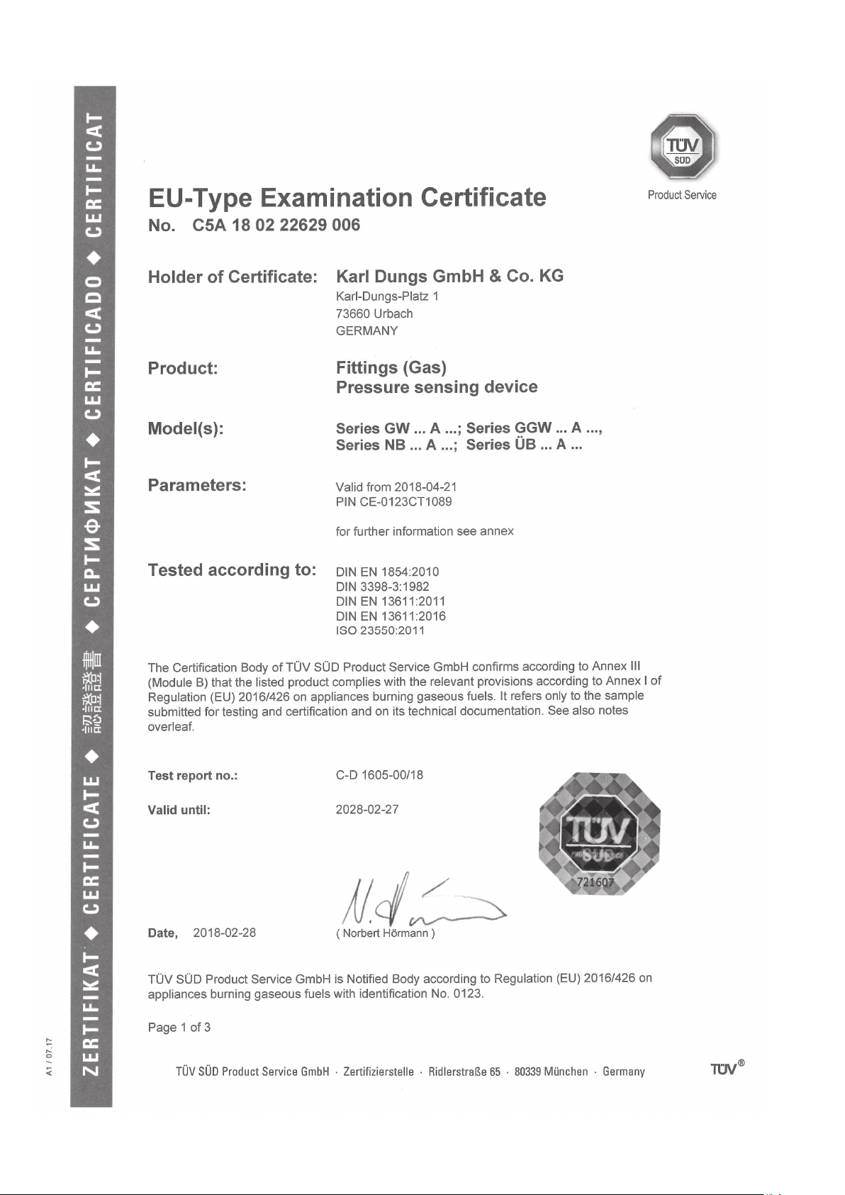
Einbaumaße / Dimensions
Cotes d'encombrement / Dimensioni [mm]
GGW … A4 / GGW … A4
Zusammenbauset Doppeldruckwächter (nicht für /2-Version)
Double pressure switch: Side-By-Side Mounting Kit (not for /2-version)
Kit de montage pour pressostat double (pas pour la version /2)
Set di montaggio per il pressostato doppio (non per versione /2)
GGW … A4 / GGW … A4
Bestell-Nr.
Order-No.
Réf. de commande
Nr. codice
213 910
Sechskantmutter M5 ISO 10511
M5 hex. nut, ISO 10511
Ecrou M5 ISO 10511
Vite esagonale M5 ISO 10511
Innensechskantschraube M5 x 12,
ähnlich ISO 4762
M5 x 12 hex. socket bolt (ISO 4762)
Vis six-pans creux M5 x 12,
similaire à ISO 4762
Vite esagonale interna M5 x 12,
simile ISO 4762
G 1/4
G 1/4
O-Ring Ø 14,3 x 2,4
O ring Ø 14.3 x 2.4
Joint torique Ø 14,3 x 2,4
O-Ring Ø 14,3 x 2,4
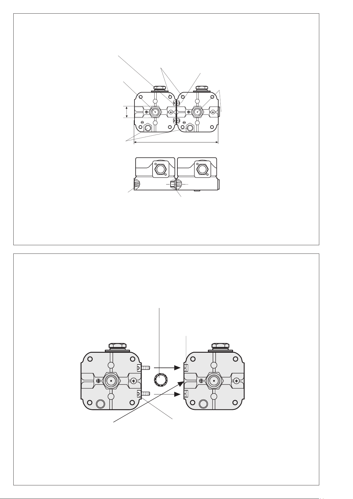
Vor Zusammenbau:
Schraube aus Meßstutzen entfernen.
Before assembly:
Remove the screw from the test nipple.
Avant assemblage :
retirer la vis de la prise de mesure.
Prima dell’assemblaggio,
togliere la vite dal raccordo per misurazione.
Sechskantmutter M5 ISO 10511
M5 ISO 10511 hex. nut
Ecrou M5 ISO 10511
Vite esagonale M 5 ISO 10511
Druckanschluß G 1/4 (+)
G 1/4 (+) pressure connection
Raccordement au fluide G 1/4 (+)
Attacco pressione G 1/4 (+)
4 x ø 4,2 für Schrauben/for screws
pour vis/per vite M4 ISO
1207,4762
Innensechskantschraube M5 x 12, ähnlich ISO 4762
M5 x 12 socket head screw, similar to ISO 4762
Vis à six pans creux M5 x 12, similaire à ISO 4762
Vite esagonale interna M5 x 12, simile ISO 4762
Verschlußschraube G 1/4
G 1/4 screw plug
Bouchon G 1/4
Tappo di chiusura G 1/4
Druckanschluß G 1/8 (-)
G 1/8 (-) pressure connection
Raccordement au fluide G 1/8 (-)
Attacco pressione G 1/8 (-)
Meßstutzen, integriert ø 9
Measurement nozzle, integrated ø 9
Prise de pression intégrée ø 9
Presa pressione integrata ø 9
O-Ring 14,3 x 2,4
14.3 x 2.4 o ring
Joint torique 14,3 x 2,4
O-ring 14,3 x 2,4
152
G 1/4
G 1/4
SW 22

9 … 16
MC • Edition 04.18 • Nr. 239 364
Einbau
GGW…A4, GGW…A4-U,
GGW…A4/2, GGW…A4-U/2
1. Der Druckwächter wird direkt
auf einen Rohrstutzen mit R 1/4
Außengewinde aufgeschraubt.
Bild 1.
2.
Nach Einbau Dichtheits- und
Funktionskontrolle durchführen.
AufvibrationsfreienEinbau
achten! Bild 2.
Installation of
GGW…A4, GGW…A4-U,
GGW…A4/2, GGW…A4-U/2
1. Screwthepressureswitchdirectly
on a tube socket with R 1/4 outer
thread (see Fig. 1).
2. After installation, perform a leak-
age and function test.
Ensure that the pressure
switch is installed free of
vibration! (see Fig. 2).
Montage
GGW…A4, GGW…A4-U,
GGW…A4/2, GGW…A4-U/2
1. Le pressostat peut se visser di-
rectement sur un piquage R 1/4"
Fig.1.
2. Après le montage contrôler la
fonction et l'étanchéité.
Veiller à ce que l'appareil ne
subisse pas de vibrations!
Fig. 2
.
Montaggio
GGW…A4, GGW…A4-U,
GGW…A4/2, GGW…A4-U/2
1. Ilpressostatovieneavvitatodiret-
tamente su un tubo di sostegno
con letto esterno R 1/4 (Fig.1)
2. Dopo il montaggio eettuare i
controlli di tenuta e funzionalità.
Evitare possibilità di vibra-
zioni! Fig 2.
1 2
Geeignetes Dicht-
mittel einsetzen!
Useproper sealing
compounds!
Utiliser une pâte à
joint adaptée!
Impiegare materi-
ale di tenuta ade-
guato!
Überdruckwächter GGW…A4
Druckanschluß G 1/4 (+)
Das Schaltwerk spricht auf Über-
druck an, der beim Über- bzw.
Unterschreiten des eingestellten
Sollwertes einen Stromkreis ein-
bzw. aus- oder umschaltet.
EinfachwirkenderDruckwächter im
Überdruckbereich. Der Druckan-
schluss G 1/8 (-) darf nicht
verschlossen werden.
Unterdruckwächter GGW…A4-U
Druckanschluß G 1/8 (-)
Das Schaltwerk spricht auf Un-
terdruck an, der beim Über- bzw.
Unterschreiten des eingestellten
Sollwertes einen Stromkreis ein-
bzw. aus- oder umschaltet.
EinfachwirkenderDruckwächter im
Unterdruckbereich. Der Druckan-
schluss G 1/4 (+) darf nicht
verschlossen werden.
Dierenzdruckwächter
GGW...A4
p+: höherer Überdruck G 1/4
p-: niedriger Überdruck G 1/8
Am Anschluss G 1/8 darf kein Un-
terdruck angeschlossen werden.
GGW...A4-U
p+: niedriger Unterdruck G 1/4
p-: höherer Unterdruck G 1/8
Am Druckanschluss G 1/8 darf kein
Überdruck angeschlossen werden.
Over-pressure switch GGW…A4
Pressure connection, G 1/4 (+)
The switching apparatus reacts to
excess pressure and activates or
switches if the pressure exceeds
or drops below a setpoint.
Simply and eciently acting pres-
sure switch for the excess pressure
range. The pressure connection,
G 1/8 (-) must not be closed or
blocked.
Under-pressure switch GGW…A4-U
Pressure connection G 1/8 (-)
The switching apparatus reacts to
inadequate pressure and activates
or switches if the pressure exceeds
or drops below a setpoint.
Simply and eciently acting pres-
sure switch for the low-pressure
range.The pressure connection,
G 1/4 (+) must not be closed or
blocked.
Dierential pressure switches
GGW...A4
p+: high positive pressure G 1/4
p-: low positive pressure G 1/8
Negativepressuremust not be con-
nected to connection G 1/8.
GGW...A4-U
p+: low negative pressure G 1/4
p-: high negative pressure G 1/8
Positive pressure must not be
connected to pressure connection
G 1/8.
Pressostat de surpression GGW …A4
Raccord de pression G 1/4 (+)
Le mécanisme de coupure réagit à
la surpression qui enclenche, dé-
clenche ou commute un circuit élec-
trique lorsque la valeur de pression
réelle est supérieure ou inférieure à
la valeur de consigne sélectionnée.
Pressostat de surpression à effet
simple. Le
raccord de pression
G
1/8
(-)
ne doit pas être fermé.
Pressostat de dépression GGW…A4-U
Raccord de pression G 1/8 (-)
Le mécanisme de coupure réagit
à la dépression qui enclenche, dé-
clenche ou commute un circuit élec-
trique lorsque la valeur de pression
réelle est supérieure ou inférieure à
la valeur de consigne sélectionnée.
Pressostat de dépression à effet
simple. Le raccord de pression
G 1/4
(+)
ne doit pas être fermé.
Pressostat diérentiel
GGW...A4
p+ : surpression plus élevée G 1/4
p- : surpression plus faible G 1/8
Aucune dépression ne doit être
raccordée au raccord G 1/8.
GGW...A4-U
p+ : dépression plus faible G 1/4
p- : dépression plus élevée G 1/8
Aucune surpression ne doit être rac-
cordéeauraccorddepression G1/8.
Pressostato per sovrapressione
GGW...A4 per attacco a G 1/4 (+)
Il meccanismo di commutazione
scatta in presenza di sovrapressio-
ne. Al superamento per eccesso o
per difetto del valore nominale tarato
il circuito verrà inserito o disinserito
o commutato.Pressostato ad azione
semplice nel campo di sovrapressio-
ne. Non chiudere il per attacco a
nell’attacco G 1/8
(-)
.
Pressostato per depressione
GGW...A4-U per attacco a G 1/8 (-)
Il commutatore reagisce al campo
di depressione, la quale al supe-
ramento per eccesso o per difetto
del valore nominale tarato innesta,
stacca oppure commuta il circuito
elettrico. Esso si può ultilizzare
anche come semplice pressostato
nel campo di depressione.
Non
chiudere il per attacco a nell’at-
tacco
G 1/4 (+).
Pressostato dierenziale
GGW...A4
p+:sovrapressione maggiore G 1/4
p-: sovrapressione minore G 1/8
Sull'attacco G 1/8 non può essere
collegata alcuna depressione.
GGW...A4-U
p+: depressione minore G 1/4
p-: depressione maggiore G 1/8
Sull'attacco della pressione G 1/8
non può essere collegata alcuna
sovrapressione.

10 … 16
MC • Edition 04.18 • Nr. 239 364
Elektrischer Anschluß
Electrical connection
Raccordement électrique
Allacciamento elettrico
IEC 730-1 (VDE 0631 T1)
M20 x 1,5
DIN EN 175 301-803
Schaltfunktion
Switching function
Schéma de fonctionnement
Funzione di commutazione
pressostato
GGW…A4, GGW…A4-U,
GGW…A4/2, GGW…A4-U/2
Erdung nach örtlichen Vor-
schriften.
Grounding acc. local regu-
lations.
Mise à la terre selon normes
locales.
Messa a terra secondo prescrizioni
locali.
Zur Erhöhung der Schaltleistung
wird bei DC-Anwendungen
< 20 mA und 24 V der Einsatz
eines RC-Gliedes empfohlen.
To increasetheswitchingcapacity,
we recommend that you use a RC
device for current values < 20 mA
and 24 V d.c. applications.
Pouraugmenterlapuissancede
rupture, l'utilisation d'un circuit
RC est préconisée pour les
applications à courant continu
< 20 mA et 24 V.
Per aumentare la potenza d'in-
serimento con applicazioni DC
< 20 mA e 24 V, consigliamo
l'impiego di un elemento RC.
Bei steigendem Druck:
1 NC önet, 2 NO schließt.
Bei fallendem Druck:
1 NC schließt, 2 NO önet.
While pressure is increasing:
1 NC opens, 2 NO closes.
While pressure is decreasing:
1 NC closes, 2 NO opens.
Pression montante:
1 NC ouvre, 2 NO ferme.
Pression descendante:
1 NC ferme, 2 NO ouvre
Con pressione in salita:
1 NC apre, 2 NO chiude.
Con pressione in discesa:
1 NC chiude, 2 NO apre
N
auf Anfrage
on request
sur demande
su richiesta
Druckanschluß
Pressure port
Prise de pression
Attacco pressione
1 DruckanschlußG1/4(+)fürGas
und Luft
1 Pressure port G 1/4 (+) for gas
and air
1 PrisedepressionG1/4 (+)pour
gaz et air
1 Attacco pressione G 1/4 (+) per
gas ed aria
2 Druckanschluß G 1/8 (–) für
Gas und Luft
2 Pressure port G 1/8 (-) for gas
and air
2 PrisedepressionG1/8 (-)pour
gaz et air
2 AttaccopressioneG1/8 (–)per
gas ed aria
Gas Gaz
Familie 1 + 2 + 3
Family 1 + 2 + 3
Famille 1 + 2 + 3
Famiglia 1 + 2 + 3
Luft, Rauch- und Abgase
Air, ue and exhaust gases
Air, fumée et gaz brûlés
Aria,gasdicombustione
e di scarico
Buntmetallfrei, geeignet für Gase
bis max. 0,1 vol. % H2S, trocken.
Itdoesnot contain anynon-ferrous
metals, suitable for gases of up to
max. 0.1 vol. % H2S, dry.
Enalliages non-cuivreux,convient
aux gaz jusqu'à max.0,1 % en vol.
d'H2S sec.
Esso è esente da metalli non fer-
rosi ed è adatto per gas no ad un
volume max. % di 0,1 H2S.
11 … 16
MC • Edition 04.18 • Nr. 239 364
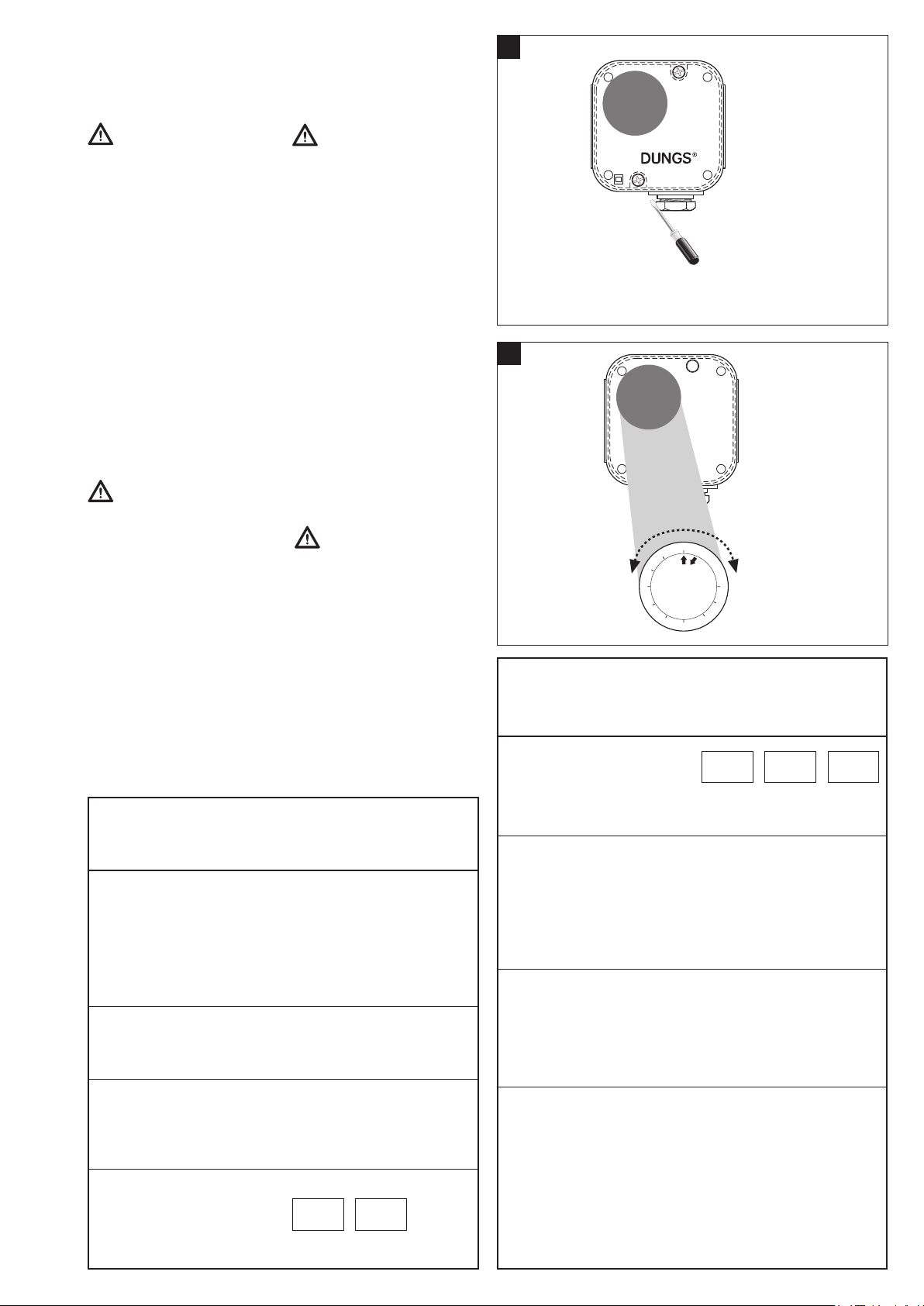
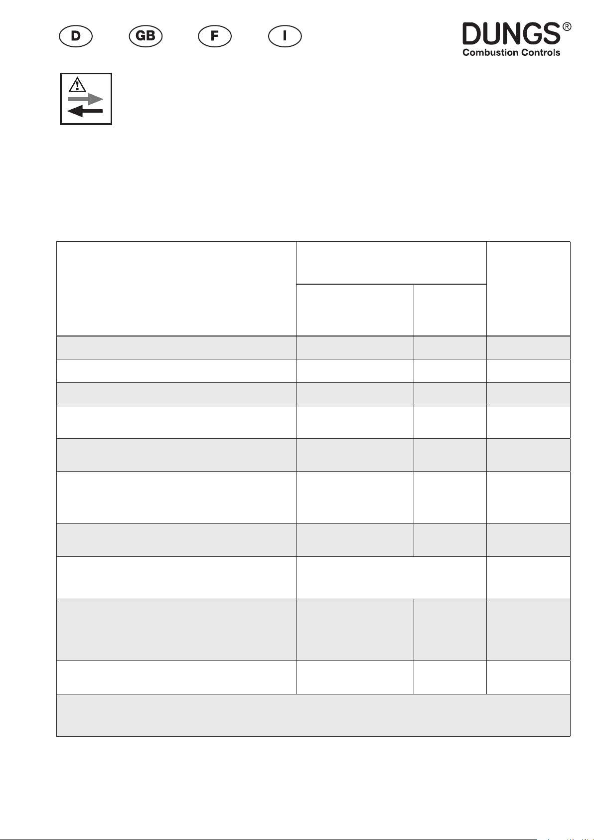
Réglage des pressostats
Enlever les vis du capot en utilisant
un tournevis No3. ou PZ 2, Fig 1.
Enlever le capot.
La protection n'est pas
garantie, contact avec des
pièces sous tension possible.
Réglage de GGW…A4,
GGW…A4-U
Régler le pressostat avec son
bouton gradué █à la valeur désirée
Fig. 2.
Respecterlesrecommandations
du constructeur du brûleur!
Le pressostat commute par pres-
sion montante: réglage Ç.
Le pressostat commute par pres-
sion descendante: réglage È.
Remonter le capot!
Regolazione del pressostato
Smontare la calotta con un attrezzo
adeguato, ossia cacciavite nr. 3 -
rispettiv, PZ 2, gura 1 Togliere la
calotta.
Non é sostanzialmente
garantita la protezione da
scariche, é possibile il contatto
con conduttori di tensione.
Regolazione GGW…A4, GGW…A4-U
Tarare il pressostato, come in gura
2, sul valore di pressione nominale
prescritto, agendosulla rotelladella
scala graduata █.
Prestareattenzionealleprescrizioni
del produttore del bruciatore!
Il pressostato scatta con pressione
insalita:regolazioneÇ.Ilpressosta-
to scatta con pressione in discesa:
regolazioneÈ.Rimontarelacalotta!
Einstellung des Druckwächters
Haube mit geeignetem Werkzeug
demontieren,Schraubendreher Nr.
3 bzw. PZ 2, Bild 1.
Haube abnehmen.
Berührschutz ist nicht
grundsätzlich gewährt,
Kontakt mit spannungsführen-
den Teilen möglich.
Einstellung GGW…A4,
GGW…A4-U
Druckwächter am Einstellrad mit
Skala █ auf vorgeschriebenen
Drucksollwert einstellen, Bild 2.
Anleitung des Brennerherstel-
lers beachten!
Druckwächter schaltet bei stei-
gendem Druck: Einstellung Ç.
Druckwächter schaltet bei fal-
lendem Druck: Einstellung È.
Haube wieder aufsetzen!
Setting the pressure switch
Dismount the hood using a suitable
tool, e.g. screwdriver no. 3 or PZ2,
Fig. 1. Remove hood.
There is no protection
againstaccidental contact.
Contact with live parts is pos-
sible.
Setting GGW…A4, GGW…A4-U
Setthepressureswitchatthesetting
wheel █ to the specied pressure
setpoint using the scale,
Fig. 2.
Follow the instructions of the
burner manufacturer!
Pressure switch switches as pres-
sureincreases:SettingÇ.Pressure
switch switches as pressure redu-
ces: Setting È.
Remount hood!
Ersatzteile / Zubehör
Spare parts / Accessories
Pièces de rechange / access.
Parti di ricambio / Accessori
Verschlußschraube mit Dichtring (1 x)
Screw plug with
sealing ring (1 x)
Bouchon avec joint (1 x)
Tappo a vite con
anello di tenuta (1 x)
...G 1/4
...G 1/8
Befestigungswinkel Metall
Angle bracket, metal
Equerre de xation métal
Cantonale di ssaggio in metallo
Set: Gerätestecker G3, 3-pol+E
Set: appliance connector G3, 3-pin + E
Kit : che d’appareil G3, 3 pôles + terre
Set spina apparecchio G3,
3 poli e terra
Montage-Set Glimmlampen
Neon glow lamp assembly set
Lampes uorescentes, kit de montage
Set di montaggio lampadina
a bagliore
grün / gree / verte / verde
Bestell-Nummer
Ordering No.
No. de commande
Codice articolo
266 044
230 397
230 288
219 659
Ersatzteile / Zubehör
Spare parts / Accessories
Pièces de rechange / access.
Parti di ricambio / Accessori
Glimmlampen Montage-Set
Neon glow lamp assembly set
Lampes uorescentes, kit de montage
Set di montaggio lampadina
a bagliore
gelb / yellow / jaune /giallo
Zusammenbauset Doppel-
druckwächter
Double pressure switch: Side-
By-Side Mounting Kit
Kitdemontage pour pressostat
double
Set di montaggio per il presso-
stato doppio
Leitungsdose 3 pol. + E
grau, GDMW
Power socket, 3-pole + E
grey, GDMW
Connecteur gris 3 pôles + terre
Presadicorrentea 3 poli+terra,
grigia, GDMW
Meßstutzen mit Dichtring (1 x)
Test nipplewithsealing ring(1 x)
Prise de mesure avec bague
d’étanchéité (1 x)
Attacco misuratore con anello
di tenuta (1 unità)
...G 1/4
...G 1/8
Bestell-Nummer
Ordering No.
No. de commande
Codice articolo
(nicht für /2-Versionen)
(not for /2-version)
(pas pour la version /2)
(non per versione /2)
213 910
210 318
266 042
230 397
230 V
248 239
24 V
248 240
1
2
Made in Germany
0,4
2,1
0,6
0 , 9
1,2
1,5
1,8
2,4
2,7
3
mbar
GGW 3A4
Made in Germany
0,4
2,1
0,6
0 , 9
1,2
1,5
1,8
2,4
2,7
3
mbar
GGW 3A4
230 V
231 773
120 V
231 772
24 V
231 774

12 … 16
MC • Edition 04.18 • Nr. 239 364
Rohrleitungsdichtheits-
prüfung: Kugelhahn
vor dem Druckwächter
schließen.
Nach Abschluß von Ar-
beiten am Druckwäch-
ter: Dichtheitskontrolle
und Funktionskontrolle
durchführen.
Niemals Arbeiten durch-
führen, wenn Gasdruck
oder Spannung anliegt.
Oenes Feuer vermeiden.
Örtliche Vorschriften be-
achten.
Bei Nichtbeachtung der
Hinweise sind Personen-
oder Sachfolgeschäden
denkbar.
Pipelineleakage test:clo-
se ball valve upstream
of the pressure switch.
On completion of work
on the pressure switch,
perform a leakage and
function test.
Never perform work if
gas pressure or power is
applied. No naked ame.
Observe local regulat-
ions.
If these instructions are
not heeded, the result
may be personal injury or
damage to property.
En cas de non-respect
de ces instructions, des
dommages corporels ou
matériels sont possible.
Ne jamais eectuer des
travaux sous pression ou
soustension.Evitertoute
amme ouverte. Observer
les réglementations.
Une fois les travaux sur
le pressostat terminés,
procéder toujours à un
contrôle d'étanchéité et
de fonctionnement.
Contrôle de l'étanchéité
de la conduite: fermer
le robinet à boisseau
sphèrique avant le pres-
sostat.
Per la prova di tenuta
delletubature:chiudereil
rubinetto a sfera davanti
al pressostato.
Al termine dei lavori eet-
tuati su un pressostato:
predisporre un controllo
sia della tenuta che del
funzionamento.
In nessun caso si deb-
bono eettuare lavori in
presenza di pressione
gaso ditensione elettrica.
Evitare i fuochi aperti e
osservare le prescrizioni
di sicurezza locali.
La non osservanza di
quanto suddetto può
implicaredannia persone
o cose.
Kondensat darf nicht
in das Gerät gelangen.
Bei Minustemperaturen,
durch Vereisung Fehl-
funktion/Ausfall mög-
lich.
Eviterl'entréedeconden-
sat dans le pressostat,
une prise en glace par
température négative
nuirait à son fonction-
nement.
Do not allow condensate
to ow into the equipment.
In case of sub-zero tem-
peratures,malfunction or
equipment failure may be
possible due to icing.
Nell' apparecchio non
deve infiltrarsi alcuna
condensa. Alle tempera-
ture negative sarebbe-
ro possibili disfunzioni
dovute a formazione di
ghiaccio.
Arbeiten am Druckwäch-
ter dürfen nur von Fach-
personal durchgeführt
werden.
Seuldupersonnelspécia-
lisé peut eectuer des tra-
vaux sur le pressostat.
Work on the pressu-
re switch may only be
performed by specialist
sta.
Qualsiasi operazione
effettuata sul presso-
stato deve essere fatta
da parte di personale
competente.
Safety
first
O.K.
Alle Einstellungen und
Einstellwerte nur in Über-
einstimmung mit der Be-
triebsanleitung des Kes-
sel-/Brennerherstellers
ausführen.
Any adjustment and appli-
cation-specic adjustment
values must be made in
accordance with the appli-
ance-/boiler manufacturers
instructions.
Eectuer tous les régla-
ges et réaliser les valeurs
de réglage uniquement
selonle moded'emploi du
fabricantde chaudièreset
de brûleurs.
Realizzare tutte le impo-
stazionie ivaloriimposta-
ti solo in conformità alle
istruzioni per l'uso del
costruttore della caldaia/
del bruciatore.
13 … 16
MC • Edition 04.18 • Nr. 239 364
HR SRB BIH SK
Die Druckgeräterichtlinie
(PED) und die Richtlinie
über die Gesamtenergieef-
zienz von Gebäuden
(EPBD) fordern eine regel-
mässige Überprüfung der
Wärmeerzeuger zur lang-
fristigen Sicherstellung von
hohen Nutzungsgraden
und somit geringster Um-
weltbelastung.
Es besteht die Notwen-
digkeit sicherheitsre-
levante Komponenten
nach Erreichen ihrer
Nutzungsdauer aus-
zutauschen:
The Pressure Equipment
Directive (PED) and the
Energy Performance of
Buildings Directive (EPBD)
require a periodic inspec-
tion of heat generators
in order to ensure a high
degree of eciency over
a long term and, conse-
quently, the least environ-
mental pollution.
It is necessary to re-
place safety-relevant
components after they
have reached the end of
their useful life:
La directive concernant les
chaue-bains à pression
(PED) et la directive sur la
performance énergétique des
bâtiments (EPBD) exigent
une vérication régulière des
générateurs de chaleur an
de garantir à long terme des
taux d‘utilisation élevés et par
conséquent une charge envi-
ronnementale minimum. Il
est nécessaire de rempla-
cer les composants relatifs
à la sécurité lorsqu‘ils ont
atteint la n de leur vie
utile:
La direttiva per apparecchi a
pressione (PED) e la direttiva
per l‘efficienza dell‘energia
totale per edifici (EPBD), esi-
gono il controllo regolare de-
gli generatori di calore per la
garanzia a lungo termine di
un alto grado di rendimento e
con ciò di basso inquinamen-
to ambientale.
Ciò rende necessaria la
sostituzione di componen-
ti rilevanti dal punto di vi-
sta della sicurezza alla
scadenza della loro durata
di utilizzazione:
Änderungen, die dem technischen Fortschritt dienen, vorbehalten / We reserve the right to make modications in the course of technical development.
Sous réserve de tout modication constituant un progrès technique / Ci riserviamo qualsiasi modica tecnica e costruttiva
Sicherheitsrelevante Komponente
Safety relevant component
Composant relatif à la sécurité
Componenti rilevanti dal punto di vista della sicurezza
Konstruktionsbedingte Lebensdauer
Designed Lifetime
Durée de vie prévue
Durata di vita di progetto
CEN-Norm
CEN-Standard
CEN-Norme
CEN-Norma
Zyklenzahl
Operating cycles
Cycle d’opération
Numero di cicli di
funzionamento di progetto
Zeit [Jahre]
Time [years]
Durée [année]
Periodo [anni]
Ventilprüfsysteme / Valve proving systems
Systèmes de contrôle de vannes / Sistemi di controllo valvole 250.000 10 EN 1643
Gas/Gaz
Druckwächter / Pressure switch / Manostat / Pressostati 50.000 10 EN 1854
Luft/Air/Aria
Druckwächter / Pressure switch / Manostat / Pressostati 250.000 10 EN 1854
Gasmangelschalter / Low gas pressure switch
Pressostat gaz basse pression /Pressostati gas di minima pressi-
one
N/A 10 EN 1854
Feuerungsmanager / Automatic burner control
Dispositif de gestion de chauage / Gestione bruciatore 250.000 10
EN 298 (Gas/Gaz)
EN 230 (Öl/Oil/
Mazout/Olio
UV-Flammenfühler1
Flame detector (UV probes)1
Capteur de ammes UV1
Sensore amma UV1
N/A
10.000
Betriebsstunden
Operating hours
Heures de service
Ore di esercizio
---
Gasdruckregelgeräte1/ Gas pressure regulators1
Dispositifs de réglage de pression du gaz1
Regolatori della pressione del gas1
N/A 15 EN 88-1
EN 88-2
Gasventil mit Ventilprüfsystem2
Gas valve with valve testing system2
Vanne de gaz avec système de contrôle de vanne2
Valvola del gas con sistema di controllo valvola2
nach erkanntem Fehler
after error detection
après détection d’erreur
dopo segnalazione di errore
EN 1643
Gasventil ohne Ventilprüfsystem2
Gas valve without valve testing system2
Vanne de gaz sans système de contrôle de vanne2
Valvola del gas senza sistema di controllo valvola2
50.000 - 200.000
abhängig von der Nennweite
depends on diameter
selon la taille
a seconda della dimensione di
connessione
10 EN 161
Gas-Luft-Verbundsysteme / Gas-air ratio control system
Systèmes combinés gaz/air / Sistemi di miscelazione gas-aria N/A 10 EN 88-1
EN 12067-2
1 Nachlassende Betriebseigenschaften wegen Alterung / Performance decrease due to ageing
Réduction de performance due au viellissement / Riduzione delle prestazioni dovuta all’invecchiamento
2 Gasfamilien II, III / Gas families II, III / Familles de gaz II, III / per i gas delle famiglie II, III
N/A nicht anwendbar / not applicable / ne peut pas être utilisé / non può essere usato
Karl Dungs GmbH & Co. KG
Postfach 12 29
D-73602 Schorndorf
e-mail info@dungs.com
Internet www.dungs.com
Karl Dungs GmbH & Co. KG
Karl-Dungs-Platz 1
D-73660 Urbach, Germany
Telefon+49 (0)7181-804-0
Telefax +49 (0)7181-804-166
Hausadresse
Head Oces and Factory
Usine et Services Administratifs
Amministrazione e Stabilimento
Briefadresse
Postal address
Adresse postale
Indirizzare la corrispondenza a
14 … 16
MC • Edition 04.18 • Nr. 239 364

15 … 16
MC • Edition 04.18 • Nr. 239 364

16 … 16
MC • Edition 04.18 • Nr. 239 364
Karl Dungs GmbH & Co. KG
Postfach 12 29
D-73602 Schorndorf
e-mail info@dungs.com
Internet www.dungs.com
Karl Dungs GmbH & Co. KG
Karl-Dungs-Platz 1
D-73660 Urbach, Germany
Telefon+49 (0)7181-804-0
Telefax +49 (0)7181-804-166
Hausadresse
Head Oces and Factory
Usine et Services Administratifs
Amministrazione e Stabilimento
Briefadresse
Postal address
Adresse postale
Indirizzare la corrispondenza a
This manual suits for next models
3
Table of contents
Other hiltbrand Switch manuals


Popular Switch manuals by other brands


HP
HP ProCurve 6208M-SX Installation and getting started guide

ATEN
ATEN CS1644a quick start guide

Moxa Technologies
Moxa Technologies EtherDevice EDS-828 Series Quick installation guide

Black Box
Black Box VSW-HDMI2-3X1 user manual

HP
HP SN6000B Hardware reference guide

Siemens
Siemens SENTRON 3NJ621 operating instructions


