234
ANSCHLÜSSE TREIBER INSTALLATION
HARDWARE INSTALLATION
Beachten Sie bitte die folgenden Installationshinweise. Da es große Unterschiede zwischen
PC‘s gibt, können wir Ihnen nur eine generelle Anleitung zum Einbau der EX-1167 geben. Bei
Unklarheiten halten Sie sich bitte an die Bedienungsanleitung Ihres Computersystems.
1. Schalten Sie Ihren Rechner und alle angeschlossenen Peripheriegeräte aus und ziehen Sie
bei allen Geräten den Netzstecker.
2. Lösen Sie die Schrauben des Gehäuses auf der Rückseite Ihres Computers und entfernen
Sie vorsichtig das Gehäuse.
3. Suchen Sie jetzt einen freien 3.5“ ront-Bay Schacht und bauen Sie die EX-1167 vorsichtig
in den ausgewählten 3.5“ ront-Bay Schacht ein. Beachten Sie, das die EX-1167 korrekt
eingebaut und befestigt ist.
4. Installieren Sie nun die mitgelieferte USB 3.0 Adapter Karte (J1) an einen internen USB 3.0
Anschluss Ihres Mainboards.
5. Schließen Sie nun das USB 3.0 Kabel der EX-1167 an die USB 3.0 Adapter Karte (J1) an.
6. Installieren Sie nun die externe Stromversorgung über den 2 pol Molex Stecker.
(siehe Abbildung Anschlüsse JP4)
7. Jetzt das Computergehäuse mit den Schrauben wieder schließen.
The EX-1167 is a internal high-speed USB 3.0 hub for 7 devices. The EX-1167 will be installed
in to a 3.5-inch front bay from your computer system. It’s possible now to connect up to seven
external USB 1.1, 2.0 or 3.0 peripherals devices to one USB 1.1, 2.0 or 3.0 port from the Desk-
top Computer. It supports all USB connections from 1.1 to 3.0. It uses data transfer rates up to
5Gbit/s. The EX-1167 design fully utilize the VIA chipset, which represents the latest in high
speed USB interface technology. It provides a secure and very high data transfer on each single
port. It is not possible to change the address or IRQ settings manually, they will be obtained
automatically by the system (BIOS) and operating system. The EX-1167 need extra power from
the PC power supply to ensure the full power of 900mA on the external and internal port.
CONNECTORS
DESCRIPTION & TECNICAL IN ORMATION
LAYOUT
Manual
Vers. 1.1 / 20.04.17
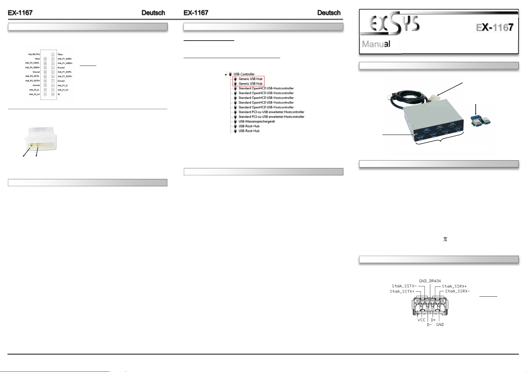
EX-1167
Compatibility: USB 2.0, 3.0 & 3.1
Operating System: All Operating Systems
Connectors: 7x USB 3.0 A-Port, 1x USB 3.0 A-Plug, 1x 2 pol Molex
Extent of delivery: EX-1167, Manual, Adapter ard, Screws
ertificates: CE / F / RoHS / WEEE DE97424562 / WHQL
USB 1-7: 7 x external USB 3.0 A-Port for Devices
Power LED
JP4:
Power plug from the
PC Power Supply
J1:
USB 3.0 Header to
2 x USB 3.0 A-Port
Attention!
Never plug in with
force or in wrong
direction.
USB 3.0 A-Port:
JP4:
Um die EX-1167 zu betreiben, muss die Karte mit dem
Stromanschluss vom PC-Netzteil verbunden werden!
Bitte auf die richtige Polarität achten!
Achtung! Stecker nie bei eingeschaltetem P ein oder
ausstecken!
1 +5V 2 GND
J1:
Achtung!
Stecker niemals umgekehrt oder mit Gewalt
einstecken und Stecker nie bei eingeschaltetem
P ein oder ausstecken!
Alle Betriebssysteme
Nach Abschluss der Hardwareinstallation erkennt das Betriebssystem den EX-1167 automa-
tisch und installiert diesen.
ÜBERPRÜ EN DES INSTALLIERTEN TREIBER:
Öffnen Sie den >Geräte-Manager<. Jetzt müssten Sie unter „USB-ontroller“ folgende Einträge
sehen:
Sind diese oder ähnliche Einträge vorhanden, ist der Hub richtig installiert.
Zur Reinigung des Gerätes verwenden Sie bitte ausschließlich ein trockenes nicht faserndes
Tuch und entfernen Sie die Verschmutzung mit leichtem Druck. Im Bereich der Anschlüsse bitte
darauf Achten, dass keine asern des Tuchs in der Buchse hinterlassen werden. Verwenden
Sie bitte zu Reinigung in keinem Fall ein feuchtes oder nasses Tuch!
REINIGUNG


