Himalaya Premium 7.0 User manual
INSTALLATION AND OPERATING INSTRUCTIONS
72-0112 03-06-18 7013500 314 SKLT 69 A
Page 1
WARNING
SECTION 1: GENERAL INFORMATION
Do not take a sauna if using
alcohol, drugs or
medications.
Pregnant women or persons
with poor health should
consult their physician before
using any sauna.
Caution re hazard: Do not
use the sauna room for
drying clothes, bathing suits,
etc. Do not hang towels
above heater or place any
object other than the rocks
supplied on the heater. If any
darkening of the wall around
the heater is noticed
discontinue sauna use
immediately.
Inspect sauna regularly for
required maintenance to
heater, control and benches.
Replace wood surfaces
which show any signs of
deterioration.
The heater gets extremely hot
during operation and should
not be touched or burns may
result.
Minors should be adequately
supervised whenever near a
hot or warming sauna.
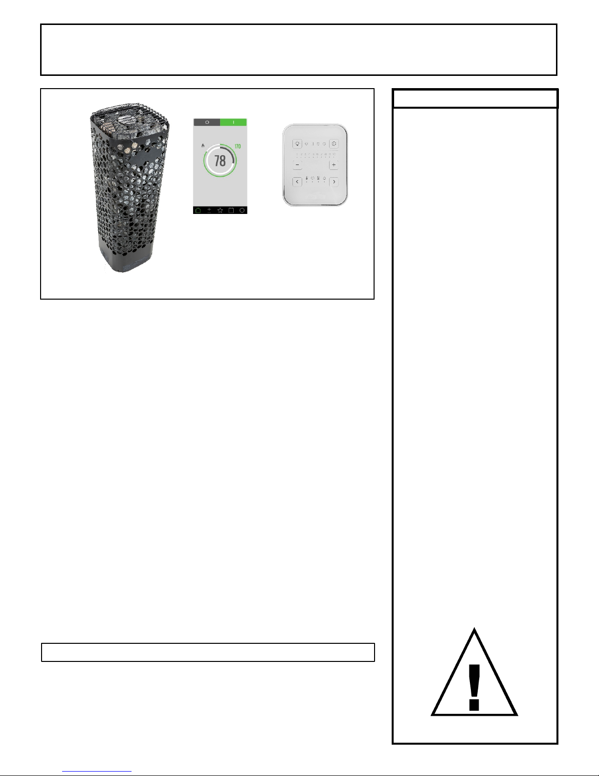
Himalaya “Premium" Series Sauna Heaters
Models 7.0, 9.0
(Type #'s 1118-702-1707, 1118-902-1707)
with Premium Control (Type # 1601-33 and 1601-33-1)
And/Or Trend Control (Type # 1601-31 and 1601-31-1).
Read all instructions carefully before installation. Please leave all
instructions and warranty with the owner.
WARNING
Prolonged exposure to elevated temperatures is capable of inducing
hyperthermia. Hyperthermia occurs when the internal temperature of the
body reaches several degrees above the normal body temperature of
98.6°F. The symptoms of hyperthermia include an increase in the normal
temperature of the body, dizziness, lethargy, drowsiness, and fainting. The
effects of the hyperthermia include failure to perceive heat, failure to
recognize the need to exit the room, unawareness of impending hazard,
fetal damage in pregnant women, physical inability to exit the room and
unconsciousness.
WARNING
The use of alcohol, drugs, or medication is capable of greatly increasing
the risk of fatal hyperthermia.
These heaters are ETL approved by Intertek for permanent installations and
electrical connections. Built with splash proof construction, the conducting
parts are protected against water. All wiring must be performed in
accordance with national and local codes. See Diagram 2 for wire and
room size requirements. These heaters are oor mounted.
Premium
Control
1601-33 or
1601-33-1
Trend
Control
1601-31 or
1601-31-1
INSTALLATION AND OPERATING INSTRUCTIONS
72-0112 03-06-18 7013500 314 SKLT 69 A
Page 2
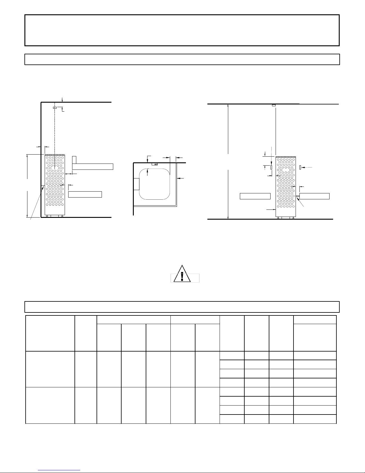
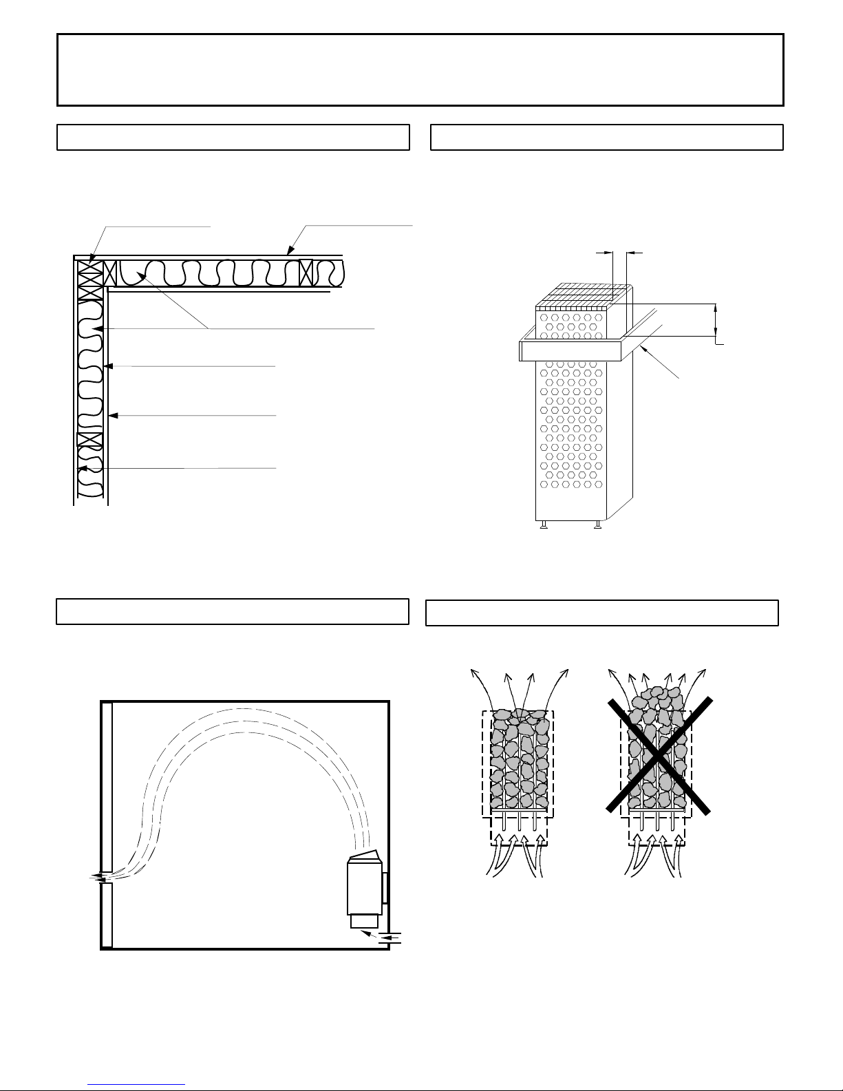
DIAGRAM 1
MOUNTING BRACKET LOCATION AND MINIMUM DISTANCE TO COMBUSTIBLE MATERIAL
Recheck your distances from the heater to
combustible materials to be sure you have
the proper minimum distances.
NOTE 1: Neutral is required for heater and control to operate. Light output from heater is 120 volts at 2 amps maximum.
DIAGRAM 2
OBSERVING MINIMUM DISTANCES IS
REQUIRED TO REDUCE THE RISK OF FIRE
WIRE SIZE
Floor
Area
Wall
Height
Volume
Cu.Ft.
Wall
Height
Volume
Cu.Ft.
Power Supply to
Heater
1 208 32.7 2 #8AWG+N+GR
1 240 28.3 2 #8AWG+N+GR
3 208 18.9 3 #10AWG+N+GR
3 240 16.4 3 #10AWG+N+GR
1 208 43.3 2 #6AWG+N+GR
1 240 37.5 2 #6AWG+N+GR
3 208 25.0 3 #8AWG+N+GR
3 240 21.7 3 #10AWG+N+GR
350
Himalaya Trend 9.0
1118-902-1707 9.0 38 sq. ft. 75" 310 96" 500
Himalaya Trend 7.0
1118-702-1707 6.8 21 sq. ft. 75" 175 96"
AMPS
HEATER MODEL /
Product Number KW
MINIMUM ROOM MAXIMUM ROOM
PHASE VAC
Heater Wall
Support
5"
All dimensions are
minimum distances
except sensor.
High Limit
Reset
Heater Bench
Support
41" 1/2
2 "
1/2
2 "
3"
75"
1/2
2 "
6"
1/2
2 " 1/2
2 "
Upper Bench
Lower Bench Lower Bench Lower Bench
1/2
2 "
Heater
Guard
Heater
Guard
Heater
Guard
Side View of Middle Room
Installation
Top View of
Corner Installation
Side View of
Corner Installation
INSTALLATION AND OPERATING INSTRUCTIONS
72-0112 03-06-18 7013500 314 SKLT 69 A
Page 3
WARNING
SECTION 2: MOUNTING OF SAUNA HEATER
SECTION 3: PLACING OF ROCKS (SEE DIAGRAMS #10 and 11)
-NOTE: Complete electrical connections and test the heater prior to this step.
Attach wall bracket to any of the mounting holes located on either side of the spine on the
rear of the heater shroud (reference diagram 4). Slide heater into position, according to
dimensions shown in Diagram 1 and mark locations for the two mounting screws. Slide
heater forward and screw two 1/4” x 1” lag bolts into sauna wall at locations marked
earlier, leaving approximately 1/8” of bolt shoulder exposed so bracket can easily slide over
bolt heads. Re-locate heater into position with key-holes of bracket locking onto lag bolts.
Adjust the leveling feet to ensure that the heater is vertical. Use a level on two sides of
heater to verify plumb.
If mounting heater in center of room, use same procedure described above but locate
mounting bracket so that it can attach to the bench framing that surrounds the heater.
The rocks supplied have been chosen to provide the best heater performance. Use of any
other type of rock may void the heaters warranty. Never operate the heater without rocks
in place! Rinse the rocks with water before placing in the heater.
Install the BWT (Bio Water Technique) tank between the second and third heating
elements resting on the top of the elements. (See diagram 11) The BWT tank has slots in
the outer ange that will align with the element loops. Install the BWT cover and the round
herb cup.
Start inserting rocks into the heater in even layers so that the 3 heating elements remain
as vertical and evenly spaced as possible. Continue to randomly drop rocks into the
heater until you are even with the top of the heating coils. Add one more loose layer to
cover up the elements and top of the BWT. (Do Not Cover Up the round herb cub on top
of the BWT!) The rocks must fully cover the heating elements. Attach the guard with the
screws provided. See Diagram #10 & 11 for rock placement.
Packing the rocks too tightly may cause the heater high limit switch to trip.
Fire sprinkler systems used
inside any sauna room should
be properly rated for sauna
room temperatures.
Do not place hands
and or arms over the BWT
when hot. Steam from BWT
may cause severe burns.
Do not pour chlorinated pool
or spa water on heater or in
the BWT.
Excessive water use on heater
may cause damage and void
warranty.
Electric Shock Hazard - High
voltage exists within this
equipment. There are no user
serviceable parts in this
equipment. All installation
and service to this equipment
should be performed by
qualied licensed personnel
in accordance with local and
national codes.
Do not construct sauna room
so as to restrict air ow
through the bottom of the
heater.
Packing the rocks too tightly
may cause the heater high
limit switch to trip.
SECTION 4: ELECTRICAL HOOK-UP
Electrical installation must be made by a licensed electrician in accordance with the
National Electrical Code and local regulations.
- NOTE: A GFCI (Ground Fault Circuit Interrupt) device is not required by ETL. A GFCI may
be installed if required by local codes but will nuisance trip during use of the product. -
CAUTION: Loose wire connections can cause heat damage to wires, terminal blocks and
other components and may void the warranty.
Remove the screws from the left and right sides of the electrical box. Remove the painted
trim piece from the front of the box. Route the feed wires through the holes provided in the
bottom of the heater and connect the wires to the terminal block. To determine the correct
wire size, refer to Diagram 2. Use copper supply wire only, suitable for minimum 90
degrees C. The heater must be grounded! See Diagram 6 for proper connections.
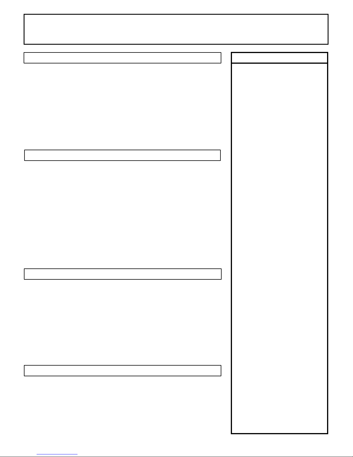
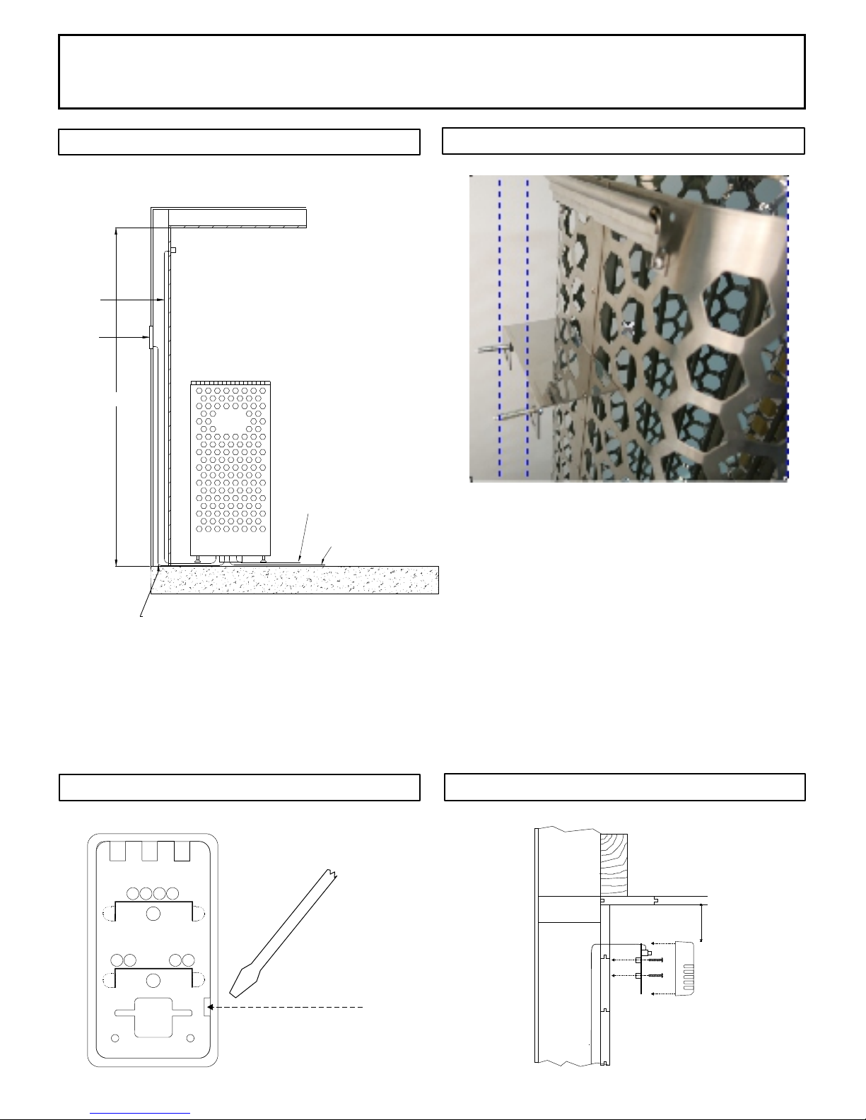
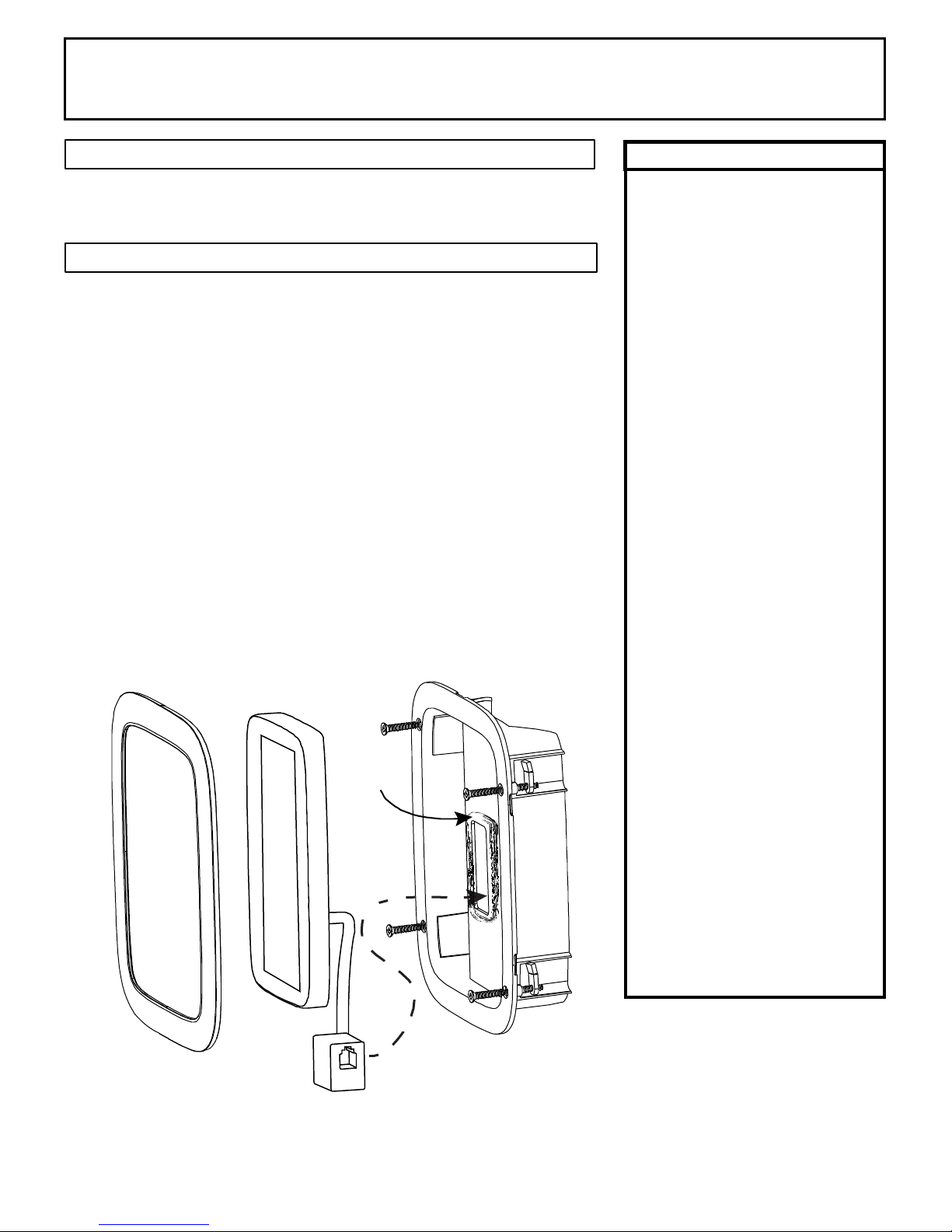
SECTION 5: TEMPERATURE SENSOR
Feed the "low voltage" sensor wire from the sensor to the sauna heater location. Sensor
wire must be routed completely separate (as per low voltage electrical wiring codes) from
any wiring carrying over 50 volts. It may be necessary to drill holes to string the wire
through the studs or ceiling joists. Route the wire to bottom of the heater and connect to
the sensor connection. Mount sensor to nished wall 3" from the ceiling directly above
the heater using two (2) screws (provided) as shown in diagrams 1, 3 & 5.
If mounting heater in the middle of your sauna room, locate the temperature sensor on the
ceiling above the heater at a point directly above one outer edge of the sauna heater
shroud. See Diagram 1.
INSTALLATION AND OPERATING INSTRUCTIONS
72-0112 03-06-18 7013500 314 SKLT 69 A
Page 4
DIAGRAM 3 DIAGRAM 4
DIAGRAM 5 DIAGRAM 5, continued
Back of
sensor
3" from ceiling to
top of sensor and
centered above
the heater.
Insert screwdriver tip here to unsnap
sensor cover from sensor.
Note vertical orientation of cover
before removing.
Bracket ts in any hexagon opening and then screws
to the wall or bench.
Sensor protective cover. Locate bottom
of sensor horizontally 3" from ceiling
and directly above the heater.
Minimum
ceiling
spacing
Trend
Control
Heater Input Power
Light Output Power
Sensor
Wire
75"
1 5 f o o t L o w Vo l t a g e C a b l e p r o v i d e d w i t h c o n t r o l .
INSTALLATION AND OPERATING INSTRUCTIONS
72-0112 03-06-18 7013500 314 SKLT 69 A
Page 5
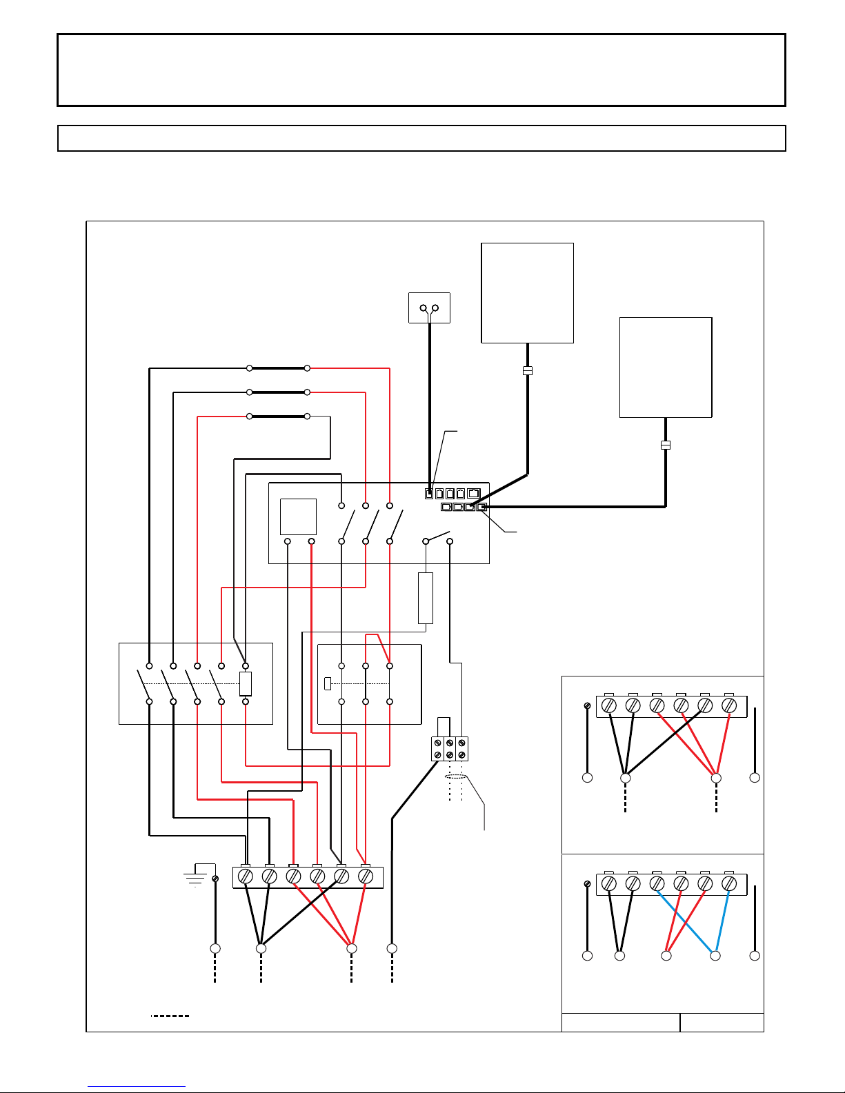
DIAGRAM 6
Himalaya Heater Models
1118-702-1707 6.8 kW
1118-902-1707 9.0 kW Sensor
Front
Element
Middle
Element
Back
Element
Premium
Control
1 2 3
P1 P2 P3
1 3 5 7 A1
246 8 A2
X1 X2 X3 X5 X7
X4 X6 X8
X13 X14
N
NH
2 3
Trans-
former
120 Volt Light Output
2.0 Amp Max
Contactor
High Limit
Switch
1601-33 or
1 2 3 4 5 6
GND
1601-33-1
Breaker
2 Amp
4 Control Ports
Sensor
L1 L2
Single Phase Connections
Field Wiring
Single Phase Wiring Diagram Color Code
Trend
Control
1601-31 or
1601-31-1
L1 L2 L3
12 3 4 5 6
Three Phase Connections
GND N
12 3 4 5 6
GND N
L1 L2
Single Phase Connections
02/21/18
354 SKLT 19 A
INSTALLATION AND OPERATING INSTRUCTIONS
72-0112 03-06-18 7013500 314 SKLT 69 A
Page 6
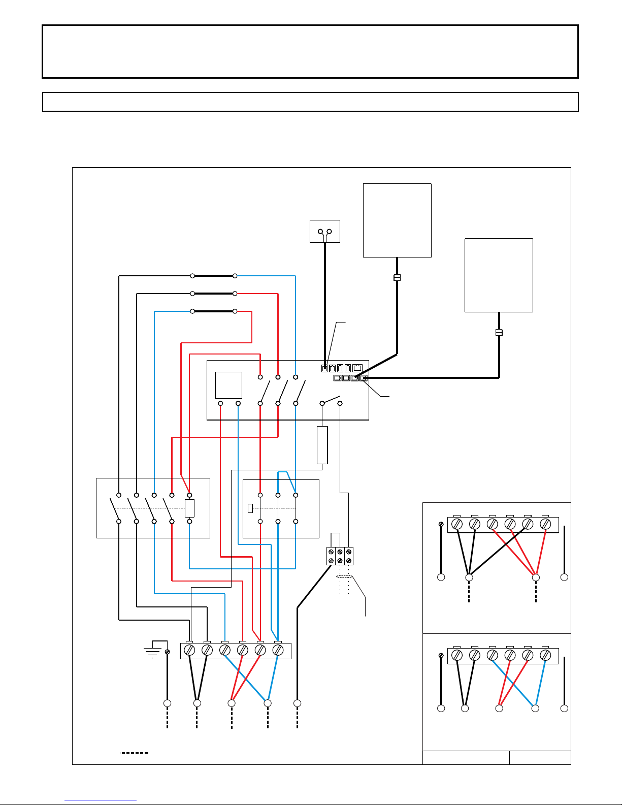
DIAGRAM 6
Himalaya Heater Models
1118-702-1707 6.8 kW
1118-902-1707 9.0 kW
Front
Element
Middle
Element
Back
Element
1 2 3
P1 P2 P3
1 3 5 7 A1
246 8 A2
X1 X2 X3 X5 X7
X4 X6 X8
N
NH
Trans-
former
120 Volt Light Output
2.0 Amp Max
Contactor
High Limit
Switch
1 2 3 4 5 6
GND
Breaker
2 Amp
L1 L2 L3
12 3 4 5 6
Three Phase Connections
Three Phase Connections
GND N
Field Wiring
12 3 4 5 6
GND N
L1 L2
Single Phase Connections
L1 L2 L3
Three Phase Wiring Diagram Color Code
Sensor Premium
Control
2 3
1601-33 or
1601-33-1
4 Control Ports
Sensor
Trend
Control
1601-31 or
1601-31-1
02/21/18
354 SKLT 19 A
INSTALLATION AND OPERATING INSTRUCTIONS
72-0112 03-06-18 7013500 314 SKLT 69 A
Page 7
WARNING
SECTION 7: CONTROL INSTALLATION & OPERATION
Do not locate benches over
heater. Refer to Diagram 1
for minimum clearance of
ceiling above heater is
required.
Minimum clearance from
heater to wooden surfaces
(benches, side walls, heater
fence etc.) is required. Refer
to Diagram 1 for specic
information.
Mounting brackets supplied.
Provides proper clearance
from wall behind heater.
Use only copper wire of the
size and type indicated in the
Heater Specication Chart
and the temperature rating
indicated on the heater
junction box.
All heaters and controls must
be grounded per NEC to
prevent electrical shock in
case of unit failure.
Electrical outlets or
receptacle must not be
installed in a sauna room.
A guardrail or fence is
required around the heater to
prevent burns from
accidental contact.
INSTALLATION ROUGH IN: Place the control inside or outside the sauna room. If
the control is installed inside a sauna room, the top of the unit cannot be higher
than 48 inches above oor. Maximum control cable length is 50 feet.
String the provided low voltage control cable through 1” holes in the wall studs or
ceiling joists from the control location to the heater. Do not use staples to secure
the low voltage cable, it may damage the cable!
Plug the control cable into the control and TEST the control BEFORE mounting!!
After testing is complete, CLEAN the mounting surface to ensure it is free from
dust. Remove the adhesive tape from the back of the control, push any excess
cable into wall cavity and press the control to the mounting surface.
CONTROL OPTIONS: This heater has two different control options. A Premium
Control (1601-33 or 1601-33-1) or Trend Control (1601-31 or 1601-31-1) can
be connected to the heater. This heater can support both at the same time as
another option.
SECTION 6: HEATER GUARD RAIL
Install a wooden heater guard to prevent the sauna bather from accidentally
touching the sauna heater. Install the heater guard rail with the dimensions shown
in Diagram 1.

INSTALLATION AND OPERATING INSTRUCTIONS
72-0112 03-06-18 7013500 314 SKLT 69 A
Page 8
A. - Off Button
B. - On Button
C. - Set Point Room Temperature
D. - Current Room Temperature
E. - Home Button
F. - Temperature Button
G. - Favorites Button
H. - Calendar Button
I. - Settings Button
A. B.
C.
D.
E. F. G. H. I.
To Start Immediately
1. Press the icon in the upper right corner
2. Icon will change color
3. System has started
Note: The sauna room set point temperature is D.
The sauna room current temperature is E.
SECTION 7: PREMIUM CONTROL (1601-33 or 1601-33-1) OPERATION
Home Screen
The Home button: touch this to return to the main screen. Here you will see the current temperature in the steam room, the bath
temperature setting, the remaining bath time (if any) and the time of day. Touch the screen to show the bath and Warm Start on/off
buttons, too.
The Settings button: touch this to display the Settings screen. Here you can adjust the temperature and duration for the current
bath. You can also manually turn on the installed options when the bath is on (and turn on some options, such as Lights, when the
bath is off). You can also save your settings as a favorite so you can always have them available for your steam bath without
having to change settings after someone else has a steam bath.
The Favorites button: Here you can select a bath with your favorite settings, once you've saved it.
The Calendar button: Here you schedule a steam bath to start and run at a later time. You can select by the day of the week or
using a calendar month and select for one time bath or recurring.
The Tool button: here you make the many selections for what functions and options are available to be used, set a PIN to limit who
can change settings, and much more.
The Change Menu arrows are used to move between related menu screens. Press < to return to the previous screen or > to
continue to the next one.

INSTALLATION AND OPERATING INSTRUCTIONS
72-0112 03-06-18 7013500 314 SKLT 69 A
Page 9
SECTION 7: PREMIUM CONTROL (1601-33 or 1601-33-1) OPERATION, Continued
Temperature and Room Light
Change temperature by pressing +
or - to desired temperature.
Press the Lighting icon to turn On
or Off the room light.
Press Screen
Press button in upper right
corner to start sauna.
Temperature Screen Options
Sauna Duration
Change sauna length by pressing
the Stop After button
Change to desired length (normal
setting is 1 hour)
Press the to accept the change
Creating Favorites
Ensure temperature and sauna
length are correct.
Press Save as Favorite
Type in Name and press
Press the to accept information.
Favorites Screen Options
Favorites
Select the Favorite to edit or start
program
Favorite’s Settings
Click on Title to change name
Change temperature by pressing +
or - to desired temperature.
Change to desired length (normal
setting is 1 hour)
Press to activate program.
Home Screen
Home Screen will appear and the
sauna heater will be started. The
temperature setting is the favorite
just chosen.

INSTALLATION AND OPERATING INSTRUCTIONS
72-0112 03-06-18 7013500 314 SKLT 69 A
Page 10
Calendar Screen Options
SECTION 7: PREMIUM CONTROL (1601-33 or 1601-33-1) OPERATION, Continued
Adding One Time Event
Click the date for the event.
Adding One Time Event
Click the + to add event.
Adding One Time Event
Select the sauna duration
and temperatures.
Press the to accept
information.
Calendar Showing Event
Scheduled
The indicated a program
is scheduled on the date.
Select the button at the top of screen
to chose Recurring Event
Click the day of the week for the event.
Select the + to add event.
Select the sauna duration and temperatures.
Press the to accept information.
Next screen will show 1 event created for the day of the week.
Repeat the process to create multiple events.
Adding Recurring Event
INSTALLATION AND OPERATING INSTRUCTIONS
72-0112 03-06-18 7013500 314 SKLT 69 A
Page 11
Calendar Screen Options
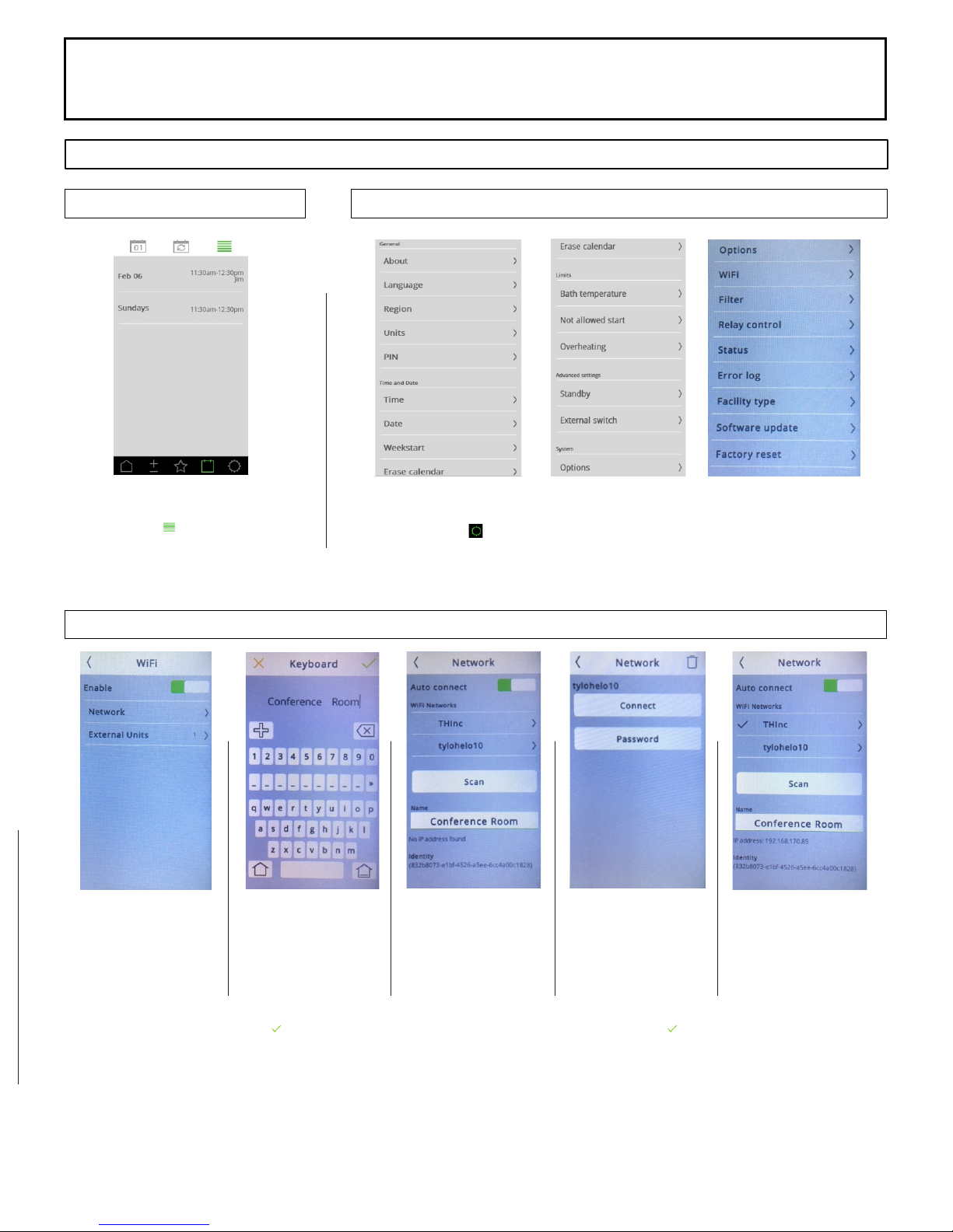
WiFi Setup Screen
SECTION 7: PREMIUM CONTROL (1601-33 or 1601-33-1) OPERATION, Continued
Setting Screen Options
Viewing Scheduled Events
Click the in the upper
right corner to see events.
Setting Options
Select the icon in the lower right corner of the control to access
settings.
Connect Control to
WiFi Network
Select the WiFi option
from Setting Screen
Select Network Option
Select Name
Select Name and name
the Control
Enter Name and select
to accept.
Choose WiFi Network
Select Scan to see all
Wi Networks
Select network to
connect
Connect Control to
WiFi Network
Select Password
Enter password and
select
to accept
WiFi Network
Check mark indicates
control is connected to
network
Networking: This control can connect to a Local WiFi Network to be operated by a Phone Application or PC Application.
Download the application from the Google Playstore or Apple Store. Search for sauna brand name and download the free
application.

INSTALLATION AND OPERATING INSTRUCTIONS
72-0112 03-06-18 7013500 314 SKLT 69 A
Page 12
SECTION 7: PREMIUM CONTROL (1601-33 or 1601-33-1) OPERATION, Continued
Phone Application Setup Screen
Application Home Screen
Select the Settings icon.
Network
Select network
Choose Sauna Control
Phone must be connected to the
same network as Sauna Control
Press Find System
Choose Control
Connect to Control
Select connect
Network Screen to Home Screen
Select the < in upper left corner to go back one screen to Network Screen
Select the < in upper left corner to go back one screen Home Screen.

INSTALLATION AND OPERATING INSTRUCTIONS
72-0112 03-06-18 7013500 314 SKLT 69 A
Page 13
SECTION 7: TREND CONTROL (1601-31 or 1601-31-1) OPERATION, Continued
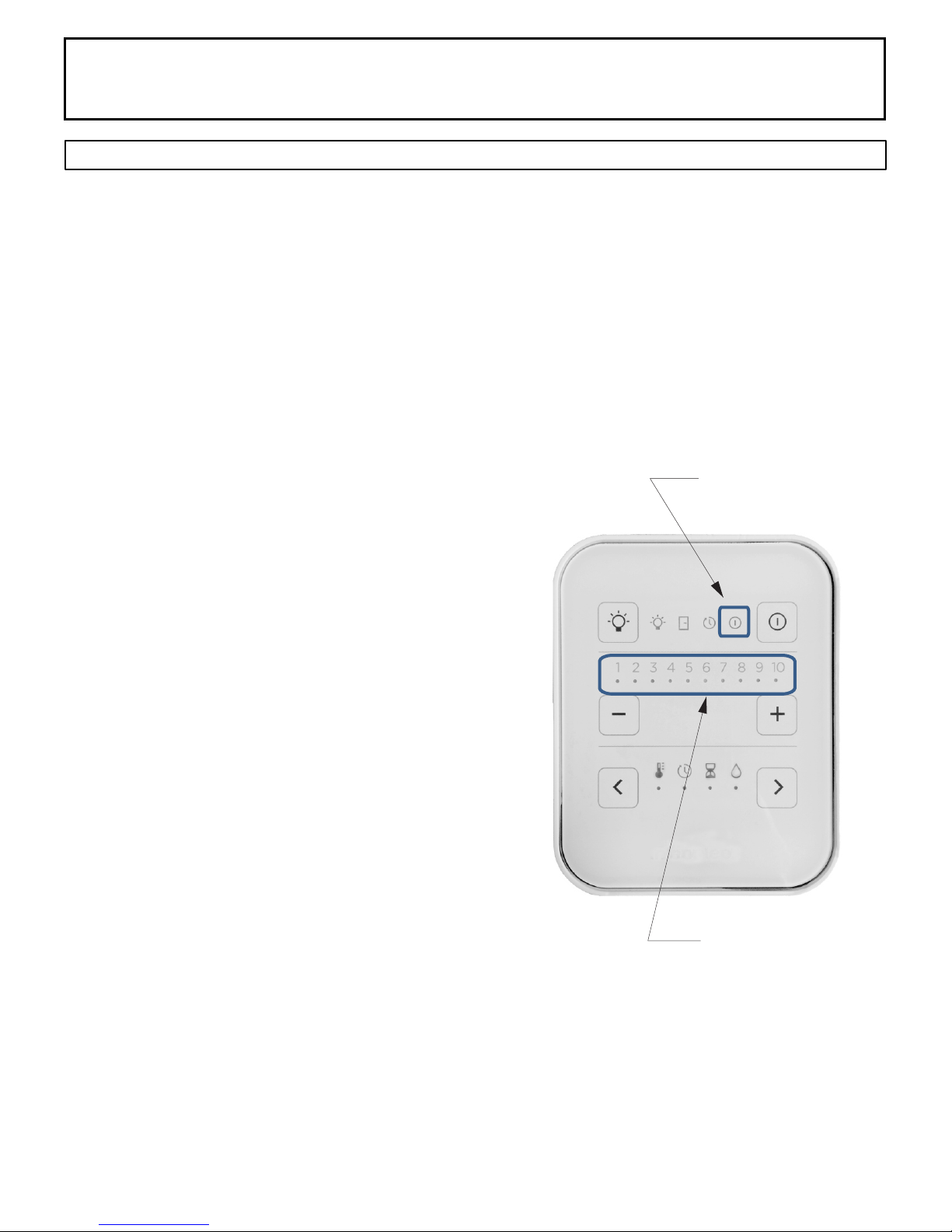
Version 1 2 3 4 5 6 7 8 9 10
1 hour 6 min 12 min 18 min 24 min 30 min 36 min 42 min 48 min 54 min 60 min
24 hour 2 hr 4 hr 6 hr 8 hr 10 hr 12 hr 14 hr 16 hr 18 hr 24 hr
LED
A. - On/Off Light Switch
B. - Indicators - lighting, door
switch (n/a), timer and the heater
C. - On/Off Sauna Switch and fault
alarms
D. - Sets the desired value
E. - Functions - Temperature, Delay
Timer, Sauna Length and Humidity
(n/a)
F. - Function Select Buttons
CONTROL OPERATION:
TURN ON LIGHT: Press the "light bulb" icon once to turn on the light and press again to turn off. (Usage of light control is
optional)
SAUNA LENGTH: (Control 1601-31) Select the sauna length function by pressing the buttons < > (F). Set the desired usage
time (0–60 minutes) using the – and + buttons. (Setting 10 equals 60 minutes)
(Control 1601-31-1) Usage time is 0 - 24 hours operation
(Setting 1 = 2 hours, setting 10 = 24 hours)
A. B. C.
D.
E.
F.

INSTALLATION AND OPERATING INSTRUCTIONS
72-0112 03-06-18 7013500 314 SKLT 69 A
Page 14
Shower
Sauna (10 - 15 min.)
Shower or swim
Rest (10 - 15 min.)
Relax with juice or water
You liked it?
Do it once again and
you will feel great.
SECTION 8: HIGH LIMIT CONTROL (RESET BUTTON)
SECTION 9: HOW TO TAKE A SAUNA
SECTION 7: TREND CONTROL OPERATION, Continued
The sauna heater has a built-in high limit control, which automatically turns off the heater
if the temperature inside in the sauna room rises to an abnormally high level.
To restart the heater, let the heater cool, then push the reset button on the lower back left
corner of the heater, see Diagram 1. If the high limit continually shuts off the heater, refer
to Section 15 for Troubleshooting.
• When taking a sauna, allow time to relax completely.
• Remove clothing and jewelry...if required, wear a towel loosely.
• Some sauna bathers enjoy the soothing effect of steam by splashing water on the
heated sauna rocks. Use only one dipper full (approx. ½ cup) at a time and keep clear
of the steam as it rises off the rocks.
• This heater has a BWT provided and must be installed in the heater.
• Water in the BWT will add a continuous humidity to the sauna room. Additional water
can be poured onto the hot rocks at any time to boost the steam level.
• Fill tank with approximately 2 cups of fresh tap water when heater is turned on (never
use water from a pool or spa!)
• Heater can operate with BWT tank empty if user does not want constant steam.
• You may add fragrance oils to the BWT if desired.
• Do not pour chlorinated pool or spa water on the heater or corrosion damage may
result.
• After 10 minutes or when perspiration begins, leave sauna and relax in dressing area...
follow with a cool shower.
• Cooling time should equal time spent in sauna. Enter sauna room again and stay 5 or
10 minutes.
• Repeat the cycle 2 or 3 times; end with a brisk shower...rinse in cool water.
• Dress when completely dry and perspiration has stopped.
• Do not smoke, exercise or drink alcoholic beverages in the sauna room.
SET TEMPERATURE: Press function button (F). Then you can choose the desired
temperature 1–10 using buttons – and +. (Setting 10 equals highest set point.)
When the desired temperature has been set and the heater is switched on, the set
temperature indicator light will remain on and the current temperature indicator LED will
ash. When the current temperature reaches the set value the indicator light will stop
ashing.
START HEAT IMMEDIATELY:
Start the heater by pressing the On/Off button. The latest temperature and usage time
settings will remain preset. A green indicator light will come on in area (B) to indicate that
the device has been switched on.
You may switch the system off before the usage time ends by pressing the same button
again. The indicator light will go out.
TIME DELAY START TIME: The control may be set to delay start mode to activate the
heater after a preset amount of time. Select the clock symbol using the function button
(F). Use the – and + (D) buttons to select the amount of hours (1–10 hours) after which
the device will switch on. Activate a later start by pressing the Start button (C).
The timer symbol light will come on (in eld B) and the selected time-lapse indicator light
will start ashing. The ashing indicator measures and indicates the time leading up to
the device being switched on. When the heater starts, the control panel will automatically
show the set temperature.
INSTALLATION AND OPERATING INSTRUCTIONS
72-0112 03-06-18 7013500 314 SKLT 69 A
Page 15
DIAGRAM 7
Locate vent under
the top bench
TYPICAL PRE-CUT WALL CONSTRUCTION
2x4" framing 1/2" wallboard
berglass insulation
1/2" wallboard
T&G soft wood
foil vapor barrier
HEATER SCREEN (GUARD RAIL)
DIAGRAM 8
VENTILATION
DIAGRAM 9 DIAGRAM 10
1. Put smaller rocks in rst around the outer perimeter of the
heating elements in layers.
2. Fill the middle sections with larger rocks.
3. Ensure the elements are vertical while lling the heater with
rocks.
4. Place rocks loosely in the center of heater to allow heat to
rise easily up in the middle of heater.
5. Be sure rocks completely cover the elements.
6. Loosely cover the tops of all elements with rocks.
7. Place heater grill on heater.
1/2
2 " min
6" min
Heater
Guard
INSTALLATION AND OPERATING INSTRUCTIONS
72-0112 03-06-18 7013500 314 SKLT 69 A
Page 16
WARNING
SECTION 10: WARNING PLACARDS
SECTION 11: ROOM CONSTRUCTION For safety purpose sauna
door must open out and not
lock.
Never use a wood stain, seal
or preservative on the inside
of your sauna room.
Light xtures get very hot
during operation. Locate
light xture where it will not
be a burn hazard.
Three metal placards are included in the Installation Instruction Envelope
packaged with every Sauna Heater. The CAUTION placard must be attached
to the interior wall of the sauna room directly above the heater where it is
visible to the bather. The French and English WARNING placards must be
attached to the door of the sauna room.
The "CAUTION" and
"WARNING" placards must be
mounted in accordance with
Section 10.
For safety and reliability, the following rules must be addressed.
• No permanent locking or latch system is to be used on the sauna door.
• Acceptable door ttings are: magnetic catches, friction catches, spring
or gravity loaded closures. The door must always open outwards.
• No shower may be installed in a sauna room.
• No electrical receptacle shall be installed inside the sauna room.
• The enclosed WARNING: Reduce the risk of overheating … warning
plate must be mounted on or alongside the door outside the sauna room
at about eye level.
• The enclosed CAUTION: Reduce the risk of re … caution plate must be
mounted on the interior wall above the heater.
• The heater should not be operated without its container properly lled
with rocks and the rock guard in place.
• If an intercom speaker is installed, it should be away from the heater and
as close to the oor as possible.
• If a room light is installed, it should be a surface mounted bracket type.
Wall mounted lights should be about 70" above the oor. Ceiling
mounted lights should be of an approved type with a junction box that is
remote to the xture itself. Use only a xture that uses A.F. or xture
type internal wiring. A 60 watt bulb should provide sufcient lighting.
• Fire sprinkler systems installed inside any sauna room should be
properly rated for sauna room temperatures.
• Always install the heater according to these installation instructions.
DIAGRAM 11
BWT tank hangs on the top of the
heating elements.
BWT tank, tank lid, and the vent cover
installed and the rocks placed around the
tank.
INSTALLATION AND OPERATING INSTRUCTIONS
72-0112 03-06-18 7013500 314 SKLT 69 A
Page 17
SECTION 14: MAINTENANCE
The sauna, like a bathroom, should be kept clean and odor free.
Towels or mats should always be used on benches and oor as perspiration otherwise penetrates the soft wood.
Air out the sauna often by keeping the door and vents open when the sauna is not in use. Saunas that are in daily use
should be washed down at least once a week to keep them clean and the air fresh. Duckboard should be removed from
the sauna, the sauna oor mopped and dried in a conventional manner, and the duckboard thoroughly scrubbed and dried
before returning to the sauna room. The sauna heater should be wiped down occasionally with a damp cloth to remove
lint and dust. The rocks should be removed once a year for cleaning and small or crumbled rocks replaced.
To clean and remove perspiration stains, use soap or detergent in warm water, best applied with a scrub brush. Badly
soiled surfaces may require sanding. Sand paper wrapped around a wooden block works well.
Benches and supporting structure must be inspected annually for potential deterioration due to age, dry rot or abuse. Any
boards with signs of deteriorations should be replaced immediately to avoid possible injury.
BWT will accumulate hard-water scale inside the tank as the water is evaporated over time. The water scale will not
immediately affect performance. It is recommended to remove the tank from the heater and clean it when you notice a
heavy accumulation or when the rocks are changed. Simply tap on the sides of the tank to loosen the scale and then
dump into a waste basket. If stubborn scale accumulation remains, you may use any commercially available de-scaling
product to remove built-up hard water scale. Follow up with a fresh water rinse before putting BWT back into the heater.
SECTION 12: VENTILATION
VENTILATION In a sauna, the air should be changed about 6 times an hour. This can be achieved by making a vent
opening (fresh air inlet) in the sauna wall directly below the heater. The air outlet must be lower than the upper benches,
as far as possible from the heater and about two feet higher than the fresh air inlet vent, See Diagram 9. It is
recommended that ventilation openings meet the requirements of UL Specication 875. The minimum opening should
be determined using one of the following formulas:
For R< 31, V ³ 9.3, For R ³ 31, V ³ 0.3R
where R = the oor area of the room in square feet and
V = the minimum vent size in square inches
SECTION 13: BWT (Bio Water Technique) Technology
The world sauna trend is moving towards higher humidity and lower temperatures. Many nd it easier to breathe, the
skin feels warm, and the humidity helps induce a sweat. This system will increase the humidity in the room allowing the
air temperature to be lower, and still feel hot.
BWT technology provides the ability to increase humidity levels in the sauna room while the heater is warming up and
during the sauna session. The continuous soft boil of water during the sauna session increases the humidity in the room
to provide a consistent feel. Additional water can be added to the rocks to provide an additional spike of humidity as
needed.
How to use BWT: Allow heater to warm up for approximately 20 minutes and add water into the tank through the side of
fragrance diffuser with slots. Add approximately 2 cups of fresh water into the tank. Do Not Use Pool or Spa Water.
Fragrance oils can be placed in the side of the fragrance diffuser without the slots. Avoid adding fragrances directly into
the water of the BWT. The oils may cause the water to foam and maybe difcult to remove the scent from the tank.
BWT tank and sleeve should always be installed in heater with rocks. Water in the tank is optional and not required if
preference is lower humidity.
INSTALLATION AND OPERATING INSTRUCTIONS
72-0112 03-06-18 7013500 314 SKLT 69 A
Page 18
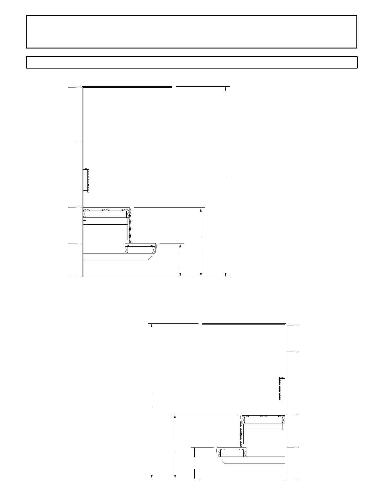
DIAGRAM 12: ROOM TEMPERATURES
Notes:
Temperatures vary in a sauna room by
height and distance from heater.
Ventilation will help reduce it but will not
eliminate temperature variations.
The hottest part of the room is always at
the ceiling directly above the sauna
heater and should not exceed 194°F
(90°C).
Air temperature will be 15°F to 25°F
lower on the opposite side of the room
from the heater close to the ceiling.
The temperatures in the elevated view
are general numbers. Each sauna room
is different due to construction variations
and ventilation.
Lower Bench
Upper
Bench
Floor
Ceiling
Lower Bench
Bench Support
Bench Support
Upper Bench
Floor
Ceiling
Head Height
Head Height
190° F
160° F
140° F
100° F
85° F
190° F
140° F
125° F
95° F
85° F
Non-Typical Ceiling Height
Typical Ceiling Height
17"
17"
35"
84"
35"
96"

INSTALLATION AND OPERATING INSTRUCTIONS
72-0112 03-06-18 7013500 314 SKLT 69 A
Page 19
SECTION 15: REPLACEMENT PARTS
1 8019-517 GUARD,ROCK,HIMALAYA,BLK,SK-ZG 1
2 8221-06 HOLDER,BWT,FRAG CUP,BLACK 1
3 2137-23 COVER,BWT TANK,W/FRAGRANCE HOLDER,HIMALAYA 1
4 N/A Item 4 is combined with Item 3 N/A
5 8100-483 TANK,WATER,BWT,(MF),HIMALAYA HTRS 1
6 3001-768 ELEMENT,HTR,2267W,208V,SEPC 226-1,HIMALAYA 3
6 3001-769 ELEMENT,HTR,2267W,240V,SEPC 226-1,HIMALAYA 3
6 3001-770 ELEMENT,HTR,3000W,208V,SEPC 238-1,HIMALAYA 3
6 3001-771 ELEMENT,HTR,3000W,240V,SEPC 238-1,HIMALAYA 3
7 8250-086 BRKT,HTR,HIMALAYA,70/90,MOUNTING 1
8 8201-115 BRKT,HOLDER,HIGH LIMIT,HIMALAYA HTR 1
9 8012-527 SHROUD,HTR,HIMALAYA,BLK,OUTER 1
10 3119-510 SWITCH,HIGH LIMIT,55.31529.960 1
11 2100-552 TERMINAL,BLOCK,4-POS,WHT 1
12 5304-019 CABLE,ASSY,FLAT,12",4-COND,RJ10/22 CONNECTORS 1
13 3100-593 FUSE,CIRBRKR,SC,2 AMP,T13-211-2A 1
14 2100-550 TERMINAL,BLOCK,6POS,SPADE,W/3JUMPERS,NLWB,1-1 1
15 8093-001 ENCL,ELECTRICAL CHASSIS,HIMALAYA 1
16 3229-015 PCA,SAUNA,RELAY,HIGH,PAL,SERVICE 1
17 3131-517 CONTACTOR,OKTA 5-1,LC7K09004M7 1
18 8026-020 STAND,ADJ.FEET,HIMALAYA 1
19 8201-039 BRKT,PCA HIGH MNT,SST,VERT,(Himalaya) (Not Shown) 1
20 8012-477 COVER,ELECTRICAL ACCESS,HIMALAYA (Not Shown) 1
INSTALLATION AND OPERATING INSTRUCTIONS
72-0112 03-06-18 7013500 314 SKLT 69 A
Page 20
SECTION 15: TROUBLESHOOTING
Control will Run but No Heat - Press the (reset) high limit switch on the back right side of heater.
Slow Heat Time or High Limit Tripping - Check rock placement, they will break down over time and reduce the air
ow in the heater. Refer to Diagram 10 for proper rock installation. Discard all rock pieces under the size of 2"
pieces. Call the number below to order more rocks if needed.
In the event of a fault occurring in the heater system (control panel, temperature sensor, etc.), the LED On/Off
indicator will ash red on the control panel.
The fault error code will be displayed with a constant LED light or a ashing LED light under numbers 1-10. See the
list below for fault codes.
Constant LED Fault Code (ones marked with “n/a” are not in use):
1 Temperature sensor not connected or it is faulty
2 n/a
3 Heater circuit board overheated
4 One or more relay defective
5 n/a
6 n/a
7 Temperature sensor
8 n/a
9 Clock disconnected
10 Power supply to clock disconnected
Flashing LED Fault Code
1 n/a
2 n/a
3 n/a
4 Temperature sensor faulty
5 Problem with device connection
6 n/a
7 n/a
8 Too many temperature sensors connected
9 n/a
10 n/a
For troubleshooting or service questions call 1-888-780-4427 and ask to speak with service. Prior to calling, please
have the Model and Type number available. You may also email us at
techsuppor[email protected]
LED Flashes Red
during a fault
1 - 10 Indicates the
fault code
This manual suits for next models
2
Table of contents
Popular Heater manuals by other brands

EUROM
EUROM Safe-t-Shine 1200 instruction manual

Desa
Desa Master WA 33 operating manual

Goldair
Goldair GMH230 operating instructions

Space-Ray
Space-Ray SRP 08 Installation, servicing and operating instructions

Black & Decker
Black & Decker MICA BXMRA1500E manual

Sure Flame
Sure Flame ID 100 instruction manual

AUTOTERM
AUTOTERM PLANAR AIR-2D 12V User's manual with installation instructions

DELTACALOR
DELTACALOR SLIM C Operation and installation manual

SUNERZHA
SUNERZHA NUANCE Assembly and operating manual

TESY
TESY HL-277W PTC Usage and Storage Instructions

Marta
Marta MT-2451 user manual

L.B. White
L.B. White TS350DF Owner's manual and instructions


