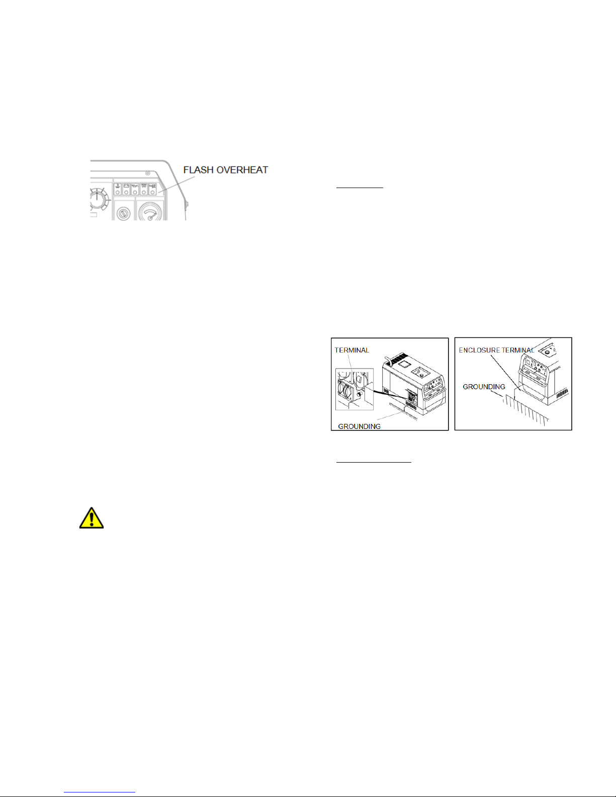
HIPower HW400A User manual

!!
!
!
Owners'Manual'
Welder/Generator'
HW400A
WARNING!
CALIFORNIA – Proposition 65 Warning
Diesel engine exhaust and some of its constituents are
known to the State of California to cause cancer, birth
defects, and other reproductive harm.

!!
!
1. INTRODUCTION
Thank you for purchasing this HIMOINSA Sound
Attenuated Diesel Engine Powered
welder/Generator.
This manual was created to help ensure the safe
operation of this equipment. To avoid unnecessary
accidents and/or repairs, it is strongly recommended
that the user closely follow all the instructions
contained in this manual.
Do not operate this equipment until you have
thoroughly read and understand the contents of this
manual.
For easy reference, this manual should always be
stored on or near the equipment.
'
The following convention will be used throughout
this manual to indicate various degrees of
warnings.
DANGER
Indicates a hazardous situation, which, if not
avoided, will result in death or serious injury.
CAUTION
Indicates a hazardous situation, which, if not
avoided, could result in minor or moderate injury.
< CAUTION >
Other types of caution
If you have any safety concerns or questions that are
not covered by this manual, please contact Himoinsa
Power Systems at 1-913-495-5557
Even some of the items noted in
Caution may lead to serious injuries. Be sure to fully
read and understand all instructions prior to operating
this equipment and follow all safety guidelines during
equipment operation.
2. SAFETY GRUIDELINES
DANGER
Suffocation from exhaust fumes
Exhaust fumes from the engine used on this
equipment contain many elements that have been
proven to be harmful to humans. Do not operate this
equipment without adequate ventilation.
!
!
!DANGER
Electrical shock
•Do not come in contact with the output
terminals during operation.
•Do not insert metal objects (such as pins or
wires) into plug-in receptacles.
•Do not touch any wiring or electrical parts
inside the equipment during operation.
•Before connecting or disconnecting a load
cable from the output terminals, ensure that
the output circuit breaker is in the OFF
position.
•Before connecting or disconnecting welding
cables from the output terminals, stop the
engine and remove the engine key. The
person connecting or disconnecting the
cables should always retain possession of
the key.
•Before performing any equipment check or
maintenance, stop the engine and remove
the engine key. The person performing the
maintenance should always retain
possession of the key.
DANGER
Burns
To avoid sustaining burns from hot vapor, do not
open the radiator cap either while operating or
immediately after stopping this equipment.
!

!!
!
!!!
DANGER
Injuries
To avoid injuries due to accidental contact with the
cooling fan, fan belt, or other moving parts, close
and lock all doors during the operation of this
equipment.
CAUTION
Suffocation from exhaust fumes
Direct exhaust fumes away from other personnel
and/or buildings
!
CAUTION
Suffocation from welding fumes
Welding fumes may contain poisonous gas and/or
dust. Ensure that there is adequate ventilation of the
welding area and if necessary, that the proper
respiratory equipment is worn
!
CAUTION
Injuries to eyes and skin
Welding helmets or hand shields containing
appropriate filter lenses and cover plates must
be worn during welding operations.
Always wear the proper protective clothing such as
long sleeve shirts, pants without cuffs, covered
pockets, sturdy shoes or boots, and durable
gloves while welding.
Battery fluid contains dilute sulfuric acid. Avoid
contact with the eyes, skin or clothing. If
contact with the acid does occur, especially
with the eyes, flush with large volumes of clean
water, and contact your physician immediately.
!
CAUTION
Electric shock
Keep water and moisture from entering the interior
of the enclosure.
CAUTION
Explosion
Do not use this equipment or charge the battery if
the battery fluid level is lower than the LOWER
level mark on the battery case.
The battery may emit highly explosive gases.
Never expose it to flames or spark producing
devices.
CAUTION
Fire
This equipment uses diesel (a flammable liquid) as
a fuel. When refueling, always stop the engine
and maintain an adequate distance from
flames and spark producing devices. Allow the
engine to cool down before refueling.
Immediately wipe up any diesel fuel or engine oil
that may be spilled. Do not use this equipment
if there are any fuel or lube oil leaks. Repair the
equipment before further use.
Temperatures around the muffler and exhaust
piping can get extremely high. Keep any
flammable items (such as fuel, gas, paint,
cloth, paper etc.) away from these areas.
Keep flammable items away from the welding area
to prevent ignition of these items by welding
spatter.
This equipment must be operated only on flat
stable surfaces and at least 3 feet away from
any obstructions (such as walls) that would
hinder airflow.
Do not connect the AC output to any indoor wiring
without an approved disconnecting device
between the generator output and the
building’s electrical service and then only if
done by a qualified electrician.
Allow the equipment to cool down before covering
it for storage.

!!
!
!
!
!
!
!
!
!
!
!
!
!
!
!
!
!
!
!
!
!
!
!
!
!
!
!
!
!
!
!
!
!
!
!
!
!
!
!
!
!
!
!
!
!
!
!
CAUTION
Burns
Due to the extremely high temperatures in these
areas, do not come in contact with the engine
or muffler during operation or immediately after
stopping the equipment.
Do not check or change the engine oil while the
engine is running. Stop the engine and allow it
to cool down prior to checking or changing the
engine oil. Opening either the line to the oil
gauge or the oil filler cap during operation may
cause injury due to hot oil.
Always wear the proper protective clothing such as
long sleeve shirts, pants without cuffs, covered
pockets, sturdy shoes or boots, and durable
gloves while welding.
CAUTION
Injuries
Lift this equipment only with the installed lifting
hook.
Operate this equipment only on a flat and stable
surface. For wheeled models, lock the wheels
during operation.
Never start the engine with loads connected to the
generator output. Prior to starting, disconnect
the loads and turn the main output circuit
breaker to OFF.
Do not move this equipment during operation.
Stop the engine before performing any equipment
checks and/or maintenance.
Do not operate this equipment if it is being
modified or if any parts have been removed.

!!
!
3. LABELS
Caution, Danger, Warning and Operation Information Labels: Make sure all information labels are
undamaged and readable. Immediately replace damaged or missing information labels. New labels are
available from your local authorized HIMOINSA distributor or dealer.
When ordering labels, use the following part numbers:
1 Suffocation from exhaust fumes (No. 19402-00194)
2 Suffocation from welding fumes (No. 19402-00195)
3 Electric Shock (No. 19402-00193)
4 Burns (No. 19402-00201)
5 Injuries (No. 19402-00199)
6 Burns (No. 19402-00200)
7 Fire (No. 19402-00166)
8 Burns (No. 19402-00256)
9 Caution Earth Leakage (No. 19402-00187)
!

!!
!
4. SPECIFICATIONS
Model
HW400A
Generating Method
Rotating Field
Welding Generator
Rated Current (A)
390 @ 60% Duty Cycle, 302 @ 100% Duty Cycle
Rated Voltage (V)
35.6
Rated Speed (rpm )
3600
No Load Voltage (A)
MAX 85
Output Change
(CC power)
Single
Current Adj. Range (A)
110 - 400
Welding Rod Diameter
5/64 – 5/16
Dual
Current Adj. Range (A)
55 - 210
Welding Rod Diameter
5/64 – 5/32
Eco
Current Adj. Range (A)
40 – 220
Welding Rod Diameter
5/64 – 3/16
AC Generator
Rated Frequency (Hz)
60
Rated Speed (rpm )
3600
Phase
1-Phase
1-Phase
3-Phase
Rated Voltage (V)
120
240
480
Power Factor
1.0
1.0
0.8
Rated Output (kVA)
2.2
4.3
15
Rating
Continuous
Engine
Model
Kubota D1005
Type
Vertical, Water-Cooled 4-Cycle Diesel Engine
Displacement (L)
1.001
Rated Output (kW/rpm)
20.4/3600
Fuel
ASTM No.2 Diesel Fuel or Equivalent
Lube Oil
API Class CC or Higher
Lube Oil Volume (Quarts/L)
5.4/5.1
Cooling Water Volume (Quarts/L)
4.5/4.3
Starting Method
12V DC Starter Motor
Battery
55B24L
Fuel Tank Capacity – (Gallons/L)
9.8 /37
Dimen
sion
Length – (Inches/mm)
59.8/1519
Width - (Inches/mm)
27.6/700
Height – (Inches/mm)
29.9/760
Dry Weight – (Pounds/kg)
972/441
5. USE
•Arc Welding (CC or CV), MIG, TIG, Gouging
•CV Power Output (Side A only)
•Auxiliary AC power source up to the rating of the AC generator.
Caution: Potential damage to this equipment or other equipment
0. This equipment is designed for the above purposes only. Do not use it for any other
purposes.

!!
!
6. PARTS

!!
!
7. PARTS
7.1. Eco Welding
This equipment incorporates the Eco
welding feature that allows welding
operations at a reduced speed (2100 rpm)
which results in lower noise levels, reduced
fuel consumption and lower emission levels
than with conventional welders.
<Caution>
0. Do not turn the output selector switch while
welding.
1. The Eco feature is available for welding only.
In the Eco mode the generator output is not
available.
7.2. CV/CC
Side A of this welder can be a Constant
Voltage Power Source. By connecting a wire
feeder to side A, and then turning the CC/CV
Selector Switch to CV, you have the ability to
perform semi-automatic welding such as
MIG, MAG, SS, etc.
When the CC/CV selector switch is
positioned to CV, Side A terminals become a
Constant Voltage Power Source. In this
position voltage is adjusted with the voltage
adjust dial A.
When the CC/CV selector switch is
positioned to CC, Side A terminals become a
Constant Current Power Source. In this
position current is adjusted with the current
adjust dial A.
<Caution>
2. Do not turn the output selector switch while
welding.
3. Side B Output Terminals can be used only as
a Constant Current Power Source.
7.3. Remote Control (Optional)
Remote control operation using the Side A
Terminals is available by plugging a remote
control into the receptacle on the lower right
side of the control panel. This will allow you to
adjust either welding voltage or welding
current from the Side A Terminals up to 295
feet away from the welder when using an
optional extension cord.
Remote Control Connection
<Caution>
4. Do not plug the remote control box into any
energized AC receptacle.
5. Do not connect other loads to the circuit that
is powering the remote control.
7.4. METERS
This equipment features reliable digital meters
for welding voltage and current and alternator
three phase output voltage and frequency
DC Volt Meter and Ampere Meter for welding
Side A and Side B.
6. When the output selector switch is
positioned at [Eco] or [Single], the Side B
meters are inoperative.
3-Phase Volt Meter
7. This meter displays the 3-Phase output
voltage of the AC generator.
Frequency Meter
8. This meter displays the AC generator
output frequency in Hertz.

!!
!
7.5. MONITOR LAMPS
This equipment has monitoring lamp
indication for WATER TEMPERATURE,
BATTERY CHARGING, OIL PRESSURE,
PREHEAT, AND OVERHEAT.
When the starter switch is placed in the RUN
position, the monitoring lamps indicating
BATTERY CHARGING, OIL PRESSURE and
OVERHEAT will turn ON. Once the engine
starts, if there are no abnormalities in the
parameters these circuits monitor, the lamps
will turn OFF. If an abnormality is detected on
any of the circuits monitored, other than
OVERHEAT, the corresponding monitor lamp
will flash, and the engine will automatically shut
down. An OVERHEAT abnormality will cause
the lamp to flash and the output of the welder
to be decreased.
If there is an automatic shutdown, turn the
starter switch to the STOP position. Investigate
the cause of and correct the reason for the
shutdown prior to trying to restart the engine.
!
Coolant/Water Temperature Monitor Lamp
'
Danger: Injuries
To avoid accidental contact with the cooling fan
or fan belts, do not operate this equipment
unless all doors are closed.
Danger: Burns
To avoid sustaining burns from hot vapor, do
not open the radiator cap while operating or
immediately after stopping this equipment.
Caution: Burns
Due to extremely high temperatures, do not
come in contact with the engine or muffler while
operating or immediately after stopping this
equipment.
If the water temperature rises to an unsafe level, the
coolant/water temperature monitor lamp will flash,
and the engine will automatically shut down. If this
occurs, check the coolant/water reservoir tank, and
refill it if needed. (Refer to Section 6-2 Checking
Coolant/Water)
If the water level is normal after shutting down
because of a coolant/water temperature monitoring
lamp situation, there is a possibility that the machine
is over loaded causing the coolant temperature to
rise to an unacceptable level. Never operate this
equipment at greater than the rated duty cycle and/or
output power.
Battery Charge Monitor Lamp
If the battery becomes unable to be charged during
operation, the battery charge monitor lamp will flash
and the engine will automatically shut down. If this
occurs, check the battery. (Refer to Section 6-5
Checking Battery)
<Caution>
9. The battery charge monitor cannot detect the
degradation of the battery or the battery fluid
level. Check the battery fluid level periodically.
(Refer to Section 6-5 Checking Battery).
Oil Pressure Monitor Lamp
'
Danger: Injuries
To avoid accidental contact with the cooling fan
or fan belts, do not operate this equipment
unless all doors are closed.
Danger: Burns
Due to extremely high temperatures, do not
come in contact with the engine or muffler
while operating or immediately after stopping
this equipment.
Prior to checking engine oil, stop the engine, and
wait until the engine cools down. If you open
either the oil gauge supply line or the oil filler
cap during operation, hot oil may cause
injury.
If the engine oil pressure drops to an unsafe
level during operation, the oil pressure
monitor lamp will flash, and the engine will
automatically shut down. If this occurs, check
the engine oil level, and refill to the maximum
level if needed.
<Caution>

!!
!
The engine oil pressure monitor cannot detect the
degradation of the engine oil itself. Check the
engine oil periodically, and change it
according to the manufacturer’s
recommendation. (Refer to Section 11
Maintenance.)
Overheat Monitor Lamp
If this equipment is used at a capacity that
exceeds its rating, it will automatically reduce
the output to a satisfactory level and the
OVERHEAT monitor lamp will flash.
The OVERHEAT monitor lamp will also flash if
the machine is being used in excess of its
rated duty cycle.
When the OVERHEAT monitor activates, the AC
generator is not usable.
If the engine automatically shuts down and none
of the monitor lamps are lit to indicate why it has
shut down, check the 20 amp and 50 amp fuses
located above the battery inside at the top of the
enclosure. If either of these fuses is burned out,
there is an electrical problem of some kind.
Investigate the cause and correct it prior to trying
to restart this equipment.
7.6. Earth Leakage Relay
'
Danger: Electric shock
Both grounding terminals of this equipment
should be earth grounded prior to the
operation of the equipment.
Even though all the terminals of the loads may
be grounded, the earth grounding terminal
and the enclosure grounding terminal should
be earth grounded.
Grounding connections should be made only
when the engine is stopped.
If the earth leakage relay activates, determine
the cause for the relay activation and correct
it before restarting this equipment.
This equipment is provided with an earth leakage
relay in the AC Circuit Breaker to detect
current leakage to ground on the loads it is
supplying. This circuit breaker will trip upon
detecting excess current to ground to protect
the operator(s) from possible electric shock.
The earth leakage relay is rated:
Sensitive Current: 30mA (or less)
(Grounding resistance: 500 ohms or less)
Sensitive time: Within 0.1 second.
(1) Grounding
A qualified electrician should ensure grounding
connections of 500 ohms or less at the following
3 points.
10. The earth grounding terminal in the output
receptacle enclosure.
11. The Outer Enclosure of the equipment
(enclosure grounding terminal).
12. The Outer Enclosure of the load(s).
(2) Operation Check
Before operating this equipment, check the
operation of the earth leakage relay as follows:
1. Start the engine.
2. Shut the Earth Leakage Circuit Breaker by
turning it to the ON position.
3. Push the test button. The device is
operating normally if the earth leakage
indication lamp turns ON and the circuit
breaker moves to the tripped position
(between ON and OFF).
4. Push the reset button. The earth leakage
indication lamp should turn OFF.
5. Reset the circuit breaker by pushing it
down to the OFF position.
6. If the above sequence cannot be
completed successfully, determine the
cause of the problem and correct it before
starting the engine.

!!
!
The Earth Leakage Relay has activated
'
Caution: Electric Shock / Injuries
If the Earth Leakage Circuit Breaker trips,
disconnect all loads connected to the AC
Generator prior to resetting it.
When the earth leakage relay activates, the
earth leakage indication lamp will turn ON and
the circuit breaker lever will move to the tripped
position (between ON and OFF).
If this happens, stop the engine, determine the
cause, and correct it.
Once the cause of the problem has been
corrected, the circuit breaker may be reset as
follows:
1. Push the reset button.
2. Reset the circuit breaker by moving it first to
the OFF Position and then back to the ON
position.
<Caution>
If the breaker trips but the lamp does not turn ON,
there is either too much load on the AC
generator or the output selector switch is in
the Eco mode while trying to supply AC loads.
If this occurs, determine the cause and
correct it prior to trying to reset the breaker.
7.7. Slow-Down Feature
The slow-down feature automatically reduces
engine speed when there is a period of
approximately 8 seconds or more that there is
no load on the engine and then automatically
increases it once again as soon as there is a
welding or AC generator demand. This feature
results in less noise, lower emissions, reduced
fuel consumption, and extended engine life.
The slow down feature can be turned on and
off by using the Slow Down Switch toggle
switch on the control panel.
'
Caution: Damage to the equipment or
other properties
If supplying loads with magnetic starters, do
not use the Slow Down feature.
<Caution>
Erratic operation of the Slow Down feature may
occur when there is a load of less than 0.5A.
If this occurs, the Slow Down feature should
be turned OFF.
If welding operations or electrical output become
erratic, turn the Slow Down feature OFF.
When the output selector switch is positioned to
Eco with the Slow Down feature in ON, the
engine will not return to high speed upon
application of load.
7.8. AC Voltage Adjusting Dial
This dial is used to adjust AC output voltage
when necessary.
<Caution>
Do not raise voltage beyond the rated capacity.
Operating loads at higher than rated voltage
can cause damage to the loads.
Lowering voltage causes the loads to draw
increased amperage which could result in
damage to the loads.

!!
!
8. Initialization and Pre-check
'
Caution: Fire, Burns, Injuries
Prior to performing any checks or adjustments to
the engine, stop the engine and allow it to
cool down.
8.1. Checking Engine Oil
When checking the engine oil, keep the
equipment level, and insert the oil dipstick all the
way in. Prior to starting the equipment, make
sure to fill the engine oil to the UPPER line
through the oil inlet.
<Caution>
If the equipment is not level, you cannot obtain
an accurate oil level reading.
Do not overfill (above UPPER line) the engine oil.
Excessive engine oil may damage the
engine.
Selecting the proper engine oil
<Caution>
Use API class CC or higher engine oil.
Temperature
Over
+68ºF
+50 to
+67ºF
-4 to +49ºF
Viscosity
SAE30
SAE20
SAE10W/30
8.2. Checking Coolant / Water
'
Danger: Injuries
To avoid accidental contact with the cooling fan
or fan belts, do not operate this equipment
unless all doors are closed.
'
Danger: Burns
To avoid sustaining burns from hot vapor, do not
open the radiator cap while operating or
immediately after stopping this equipment
'
Caution: Burns
Due to extremely high temperatures, do not come
in contact with the engine or muffler while
operating or immediately after stopping this
equipment.
Check to see if the coolant/water level is
between the FULL and LOW levels in the sub
tank. If the coolant/water is below the LOW
level, fill the tank and the radiator accordingly.
(1) Filling the Sub Tank
1 Remove the sub tank cap.
2 Add coolant to the FULL level.
3 Re-install the cap.
(2)Filling the Radiator
1 Remove the top plate.
2 Remove the radiator cap.
3 Add coolant to the top.
4 Re-install the radiator cap.
5 Re-install the top plate.
<Caution>
Use soft water, such as tap water.
If the ambient temperature is near freezing, use
Long Life Coolant (LLC) at a mixture ratio of
30%-45%, depending on the ambient
temperature.
This equipment has a 30% mixture ratio of LLC
when shipped from the factory.
Replace LLC at yearly intervals or 2000 hours of
operation whichever comes first.
Sub Tank

!!
!
Suggested!LLC!Mixture!Ratio!
Lowest Ambient
Temperature
+5ºF
-4ºF
-22ºF
Mixture Ratio
30%
35%
45%
8.3. Checking Fuel
'
Caution: Fire
Do not operate this equipment with any fuel leak.
Wipe up any spilled fuel immediately.
<Caution>
Use Diesel fuel, ASTM D975 No.2-D.
To help prevent solid contaminants from entering
the fuel system, the fuel fill strainer should
always be used.
To help prevent fuel spills, fill the fuel tank slightly
less than full when refueling.
8.4. Checking Fuel, Engine Oil and Water
Leakage
'
Caution: Fire
Do not use this equipment if there is any fluid
leakage. Repair the cause of the leak prior to
starting the equipment.
Checking for fuel, oil and coolant/water
leakage can be done by opening the side
doors and visually inspecting all fluid
connections.
8.5. Checking Battery
'
Caution: Injuries to eyes and skin
Battery fluid contains diluted sulfuric acid. Avoid
contact with eyes, skin or clothing.
If contact with the acid does occur, especially
with the eyes, immediately flush with large
volumes of water and immediately contact a
physician.
'
Caution: Fire
The battery may emit highly explosive gases.
Never expose it or the surrounding
environment to flames or spark producing
devices.
The factory installed battery has clear sides with the
upper and lower fluid levels clearly marked. Do not
operate this equipment unless the fluid level is
between the upper and lower fluid level marks. If the
fluid level is low, add distilled water to fill it to the
upper level mark.
Make sure that the battery cables are firmly secured
to the posts. Tighten the clamps if necessary.
The battery acid specific gravity should never be
allowed to fall below 1.23. This may be checked by
using a hydrometer. Re-charge the battery if specific
gravity is below 1.23.
!
Replacing the battery
12.1. If battery replacement becomes
necessary, remove the clamp and cable
from the negative (-) post of the battery.
Always remove the negative side first.
12.2. Remove the hold-down clamp from
the battery.
12.3. Remove the clamp and cable from
positive (+) post of the battery.
12.4. Remove the battery from the battery
rack.
12.5. Reinstall a new battery in the reverse
order. Always connect the positive (+) post
of the new battery first.
12.6. The factory installed battery is a
55B24L.

!!
!
9. Operation
'
Danger: Suffocation from exhaust
fumes
Exhaust fumes from the diesel engine on this
welder contain many elements that have
been proven to be harmful to humans. Do
not operate this equipment without
adequate ventilation.
Do not direct exhaust fumes toward
pedestrians or buildings.
'
Caution: Fire
Temperatures around the muffler and
exhaust piping can get extremely high.
Keep any flammable items (such as fuel,
gas, paint, etc.) away from these areas.
This equipment must be operated on flat
surfaces and, at least 3 feet away from
any obstructions, such as walls, that could
hinder air flow.
'
Caution: Injuries
This equipment must be operated only on flat
surfaces. Wheeled models must have the
wheels locked in place prior to starting the
equipment.
Before starting the engine, be sure to
disconnect all loads and open (OFF
position) both the single phase and three
phase breakers.
1.1. Starting
1. Turn the single phase and three phase
breakers (1-P and 3-P) to the OFF position.
2. Open the fuel shutoff valve.
3. Turn the Slow-Down switch to ON.
4. In cold weather there may be a need to
pre-heat the engine prior to starting. If this
is the case, turn the start switch to the pre-
heat position and hold it there until the pre-
heat light goes out.
5. Turn the start switch to START.
Do not engage the starter motor for more
than 15 seconds.
Wait 30 seconds or more between
cranking cycles.
6. Release the start switch as soon as the
engine has started. Once the engine has
started, never turn the start switch to
START.
7. Let the engine idle for approximately 5
minutes before welding or applying an AC
load.
Restarting the engine after running out of fuel.
This equipment is equipped with an automatic
air bleed feature that allows easily restarting
the engine after running out of fuel. If this
machine runs out of fuel, use the following
procedure for re-starting.
1. Turn the start switch to the STOP position.
2. Refill the fuel tank.
3. Turn the Slow-Down switch to ON.
4. Turn the start switch to the START position
and engage the starter motor for
approximately 10 seconds until the engine
starts.
5. Release the starter switch once the engine
has started.
6. The engine will run erratically until all the
air has been bled out. Wait for
approximately 1 minute before adding load
to allow the engine speed to become
stable.
<Caution>
Do not turn the Slow-Down switch to OFF or
connect loads until the air is completely
extracted. The air is completely extracted
when engine speed becomes stable.
1.2. Stopping
1. Open (place in the OFF position) the single
phase and three phase breakers (1-P and
3-P).
2. Turn the Slow-Down switch to ON.
3. Let the engine idle (cool down) for about 5
minutes.
4. Turn the start switch to the STOP position.
5. After the engine has stopped, shut the fuel
shut-off valve.

!!
!
10. Welding Operation
10.1. Selection – Welding Cable
Always use welding cable of sufficient size for the desired welding amperage at the distance from the welder that
the welding will be occurring.
<Caution>
Welding cables should be used unstrained. The ampacity of the welding cables is decreased if the welding
cables are coiled.
10.2. Polarity
There are two welding output terminals, + and -.
Connect leads to the output terminals to correspond to the type of welding to be performed in accordance
with the following table:
(1) Welding Rod
Application
Connection
Normal Polarity
General Welding
+ To Ground (Material)
- To Holder (Rod)
Reverse Polarity
Thin Plate, Build-Up Welding,
Stainless Steel
+ To Holder (Rod)
- To Ground (Material)
(2) Semi-automatic wire feeder
Application
Connection
Normal Polarity
Self-Shield (Small Diameter)
+ To Ground (Material)
- To Holder (Rod)
Reverse Polarity
MIG Welding
MAG Welding
Self-Shield (Big Diameter)
+ To Torch (Wire)
- To Ground (Material)
10.3. Connection – Welding Cable
'
Danger: Shock
Before connecting or disconnecting welding cable from the welding output terminals, stop the engine, and
remove the engine key. The person connecting or disconnecting the cable should maintain possession of the
key.
1. Stop the engine.
2. Connect the welding cable securely to the welding output terminals that are to be used.
3. After connecting the cables, close the output terminal covers before commencing to weld.

!!
!
Welding Rod
Eco (Single)
Single
Dual
Welding Rod
5/64 –3/16
Welding Rod
7/64 –5/16
Welding Rod
5/64 –5/32
Welding Output Terminal
A
Welding Output Terminal
A
Welding Output Terminal
A
and
Welding Output Terminal
B
Semi-Automatic Wire Feeder
Eco (Single)
Single
Dual
Welding Wire
MIG/MAG:.023 –.030
Self-Shield: .035 –1/16
Welding Wire
MIG/MAG: .023 –.045
Self-Shield: .035 –5/64
Welding Wire
MIG/MAG: .023 –.030
Self-Shield: .035 –1/16
Welding Output Terminal A
<Caution>
•Never connect output leads to the output terminals without using crimp on lugs on the leads.
Connections without lugs may lead to a high resistance connection resulting in excess heat being
developed and burning out of the terminal.
•Side B Output Terminals are for Constant Current Power (CC) only. You cannot get Constant
Voltage Power (CV) from the Side B Terminals.
10.4. Duty Cycle
Duty cycle is the percentage of time that welding can be done in a 10 minute period. This equipment has a
rated duty cycle of 60%. This means that welding can be performed for 6 minutes within every 10 minute
time period.
10.5. Welding
'
Caution: Suffocation from welding fumes
Welding operations may produce fumes and gases that could be hazardous to the operator’s health. Do not
breathe these fumes and gases. Wear the proper respiratory equipment and provide adequate ventilation
whenever welding.
'
Caution: Injuries to eyes and skin
Use shields with the proper filters and cover plates to protect your eyes while welding. Shields and filters
should comply with ANSI Z87.I standards. Wear the proper protective clothing while welding.
Caution: Fire
Keep all flammable items an adequate distance from the welding area while welding
'
Caution: Burns
Always wear appropriate protective clothing and eye protection when welding
<Caution>
Never turn the output selector switch while welding. Operation of this switch during welding can cause
damage to the switch.

!!
!
This equipment allows two operators to weld simultaneously with minimal affect on each other.
Each operator can individually adjust their own welding current.
(1) Stick Welding
1. Turn the CV/CC selector switch to CC.
2. Turn the output selector switch to Eco, Single or Dual, according to the desired mode of operation.
3. Adjust welding amperage using the current adjust dial for the side being used (A or B). The following
table gives the approximate amperage for the corresponding position on the current adjust dial.
Position
Welding Current at the dial position
MIN
1
2
3
4
5
MAX
1 Person
Eco
40
60
100
140
180
210
220
Single Use
110
140
200
260
320
380
400
2 Persons
Dual Use
55
70
110
140
170
200
210
These values are approximations only. Factors such as the length of the welding cables and the ambient
temperature will affect the actual value.
When the remote control is used, these values may also vary.
(2) Semi-Automatic Wire Feeder
1. Turn the CV/CC selector switch to CV.
2. Turn the output selector switch to Eco, Single or Dual, according to the desired mode of operation.
3. Adjust voltage using the Current Adjust Dial A. Refer to the following table.
Position
Welding Voltage (V) / Amperage (A) at the dial position
MIN
1
2
3
4
5
MAX
1 Person
Eco
V
18
18
19
20
24
25
25
A
40
50
80
110
200
220
220
Single Use
V
18
18
20
24
31
34
36
A
60
60
90
190
270
350
390
2 Persons
Dual Use
V
18
18
20
24
24
24
24
A
60
60
100
190
210
210
210
These values are approximations only. Factors such as the length of the welding cables and the ambient
temperature will affect the actual value.
When the remote control is used, these values may also vary.

!!
!
11. Generator Operation
11.1. Ratings
3-Phase 480V Output Receptacle
Maximum output from this receptacle is 15KVA
(12 kW), 18 amps, at 480 v
1-Phase 120/240V Output Receptacle
Maximum total single phase output from the
120/240 volt single phase receptacle is 4.3 kVA
(4.3 kW), 18 amps at 240 V.
1-Phase 120V Output Receptacle
Maximum total single phase output from the 120
volt duplex receptacle is 2.2 kVA (2.2 kW), 18
amps at 120 V.
11.2. Operation
'
Danger: Electric shock
Before connecting or disconnecting load cables
to or from the receptacles, turn the circuit
breakers (3-P and 1-P) to the OFF position.
The Earth Grounding Terminal and the enclosure
Ground Terminal should always be connected to
an earth ground while operating this equipment.
Grounding connections should be made only with
the engine not running.
If the Earth Leakage Circuit Breaker trips on fault,
determine the cause and correct it prior to
resetting and shutting the breaker.
'
Caution: Injuries
Do not plug loads into the receptacles until it has
been verified that the load on/off switch is in the
off position.
<Caution>
The AC Volt meter reads three phase output
voltage whenever the engine is operating,
regardless of the position of the single phase and
three phase breakers.
1. Start the engine in accordance with Section 7-
1 Starting.
2. Verify that the Three Phase and Single Phase
breakers are in the OFF position.
3. Verify that the load on/off switch is in the off
position.
4. Connect the load to the output receptacles.
5. Turn the Three Phase and Single Phase
circuit breakers to the ON position.
6. If the electrical demand exceeds the rated
output current, the Earth Leakage Circuit Breaker
will trip due to overload.
7. '
Caution: Injuries
Turn all load on/off switches to OFF prior to
resetting a tripped Earth Leakage Circuit Breaker.
7. After the cause of the overload has been
determined and corrected, reset the circuit
breaker by first taking it to the OFF position
and then back to the ON position.

!!
!
12. Simultaneous Use of Welding and Generating
The circuit breakers (3-P and 1-P) are affected only by the AC Generator Output. Simultaneous use of the
welder and generator could lead to overloading the engine. Limit AC Generator power use in accordance with
the following table.
Welding Output
AC Power Output
Amperage
Output Selection
3-Phase Output
1-Phase Output
60A
Dual
9.0kVA
4.3kVA
120A
Dual
8.5kVA
4.3kVA
140A
Dual
8.0kVA
4.3kVA
170A
Dual
7.5kVA
4.3kVA
240A
Single
2.5kVA
2.5kVA
300A
Single
2.0kVA
1.5kVA
380A
Single
0kVA
0kVA
<Caution>
•Eco welding power and AC generator power are not available simultaneously.
•Weld quality could be affected when using AC power while welding.
13. Checks and Maintainance
1. '
Danger: Electric Shock, Injuries
•Before performing any equipment check or maintenance, stop the engine and remove the engine
key. The person performing the maintenance should always retain possession of the key.
•
Caution: Fire, Burns
•This equipment uses diesel (a flammable liquid) as a fuel. When refueling, always stop the engine
and maintain an adequate distance from flames and spark producing devices. Always wait until the
engine cools down before refueling.
<Caution>
•With the exception of the pre-startup checks, only qualified technicians should perform checks and
maintenance work.
•Those maintenance items marked QT should be performed only by factory trained qualified technicians.
•Use only genuine replacement parts.
To maximize the useful life of this welder/generator, we recommend the periodic equipment checks and
maintenance as shown on the table on the following page. Use the hour meter as the guide for the operating
time.

!!
!
Check Items
Startup
Check
Check
At 50hrs
Every
100 hrs
Every
200 hrs
Every
400 hrs
Every
1000 hrs
Every
2000 hrs
1
Check /Add Fuel
X
2
Check/ Add Engine Oil
X
3
Engine Oil Change
1st
X
2nd or
after
X
4
Engine Oil Filter Change
1st
X
2nd or
after
X
5
Check/Add
Water/Coolant
X
6
Water/Coolant Change
X or
one year
7
Clean Fuel Strainer
1st
X
2nd or
after
X
8
Change Fuel Filter
X
9
Drain Water/Clean Fuel
Tank
X
10
Check for Fuel, Oil, and
Water Leakage
X
11
Check/Add Battery
Water
X
X Clean
X
Change
12
Clean Air Filter Element
1st
X
2nd or
after
X
13
Change Air Filter
Element
14
Adjust V-Belt Tension
1st
QT
2nd or
after
QT
15
Change V-Belt
QT or
2 years
16
Clean Radiator Fins
QT
17
Flush Radiator
QT
18
Change Fuel Hose, Oil
Hose, Vibration-
Absorbing Rubber
QT or
2 years
19
Adjust Engine Valve
Clearance
QT
Adjust
QT
Plane
20
Check/Adjust Injection
Nozzle
QT
21
Check/Adjust Injection
Pump
QT
Other manuals for HW400A
1
Table of contents
Popular Welding System manuals by other brands

EWM
EWM Wega 401 M1.02 FKG operating instructions

Parkside
Parkside PPS 40 B2 Operation and safety notes translation of the original instructions

ANDELI
ANDELI TIG-250GPLC user manual

SFS intec
SFS intec isoweld3000 operating instructions

Michigan Welding
Michigan Welding MIG135 operating instructions

zika
zika MIG500 owner's manual

GYS
GYS KRONOS 250M manual

Kemppi
Kemppi MASTER MLS 1600 Operation instructions

Hobart Welding Products
Hobart Welding Products Champion Elite owner's manual

AUTO ARC
AUTO ARC 120 owner's manual

Lincoln Electric
Lincoln Electric OPTIMARC AC/DC 350-TP Operator's manual

MK Welding
MK Welding PC 40 PFC user manual