Asahi/America, Inc. 7 Shop 12 O&M Manual
2102D
Engineering & Rental - 14 pages
6.
Initial Heating
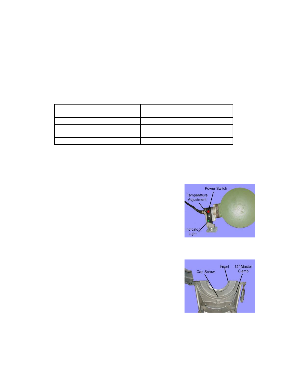
A. Check whether the heating plate has reached the working temperature (see heating
element temperature setting or the welding parameters). The working temperature
is reached when the control lamp goes out (thermostatically controlled) or if the
lamp blinks in short intervals (electronically controlled).
B. Place the heating plate between the two ends the
pipe to be welded. Bring the pipe ends against the
heater applying the proper initial melt pressure
(see charts at the end of this manual for proper
welding pressures). Lock the clamps in place with
the locking nut.
C. Watch for a continuous bead to form around both
pipe ends (see pipe manufacturer or DVS
standards for size).
D. Lower pressure until the proper melt pressure is reached (almost zero).
Note: If the clamps are moved too far in this direction, the pipe may
move away from the heater, causing a bad weld.
7.
Heat Soak
A. With the pressure almost at zero, begin to time the heat soak time (see
welding parameters). It is important to assure that the pipe ends remain in full
contact with the heating element.
8.
Change Over Time
A. Move the pipe ends apart. Remove the heating element and then bring the pipe
end back together.
B. Bring the pressure back to the original weld pressure and lock the clamps in
place. These steps must be performed within the allowable change over time.
9.
Cooling Time
A. Keep the machine under pressure until the cooling time has expired.
B. For PP and HDPE, cooling time can be reduced by 50% under the following
conditions:
I. Prefabrication under workshop conditions
II. Low additional pressure when unclamping
III. No additional pressure during further cool down
IV. System will not see pressure until cool down is complete