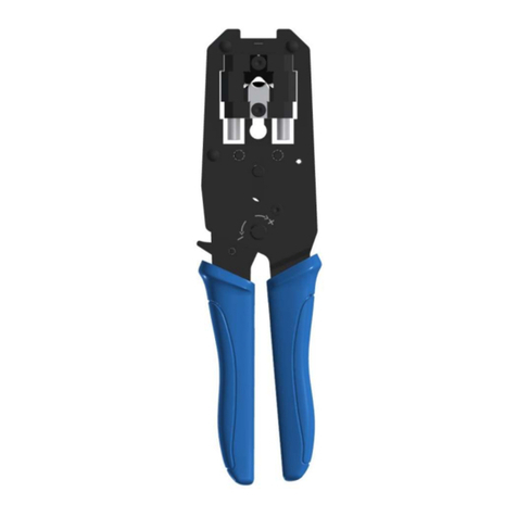
Hirose HT601/TM21P-88P User manual

MANUAL INSULATION
DISPLACEMENT TOOL
HT601/TM21P-88P
INSTRUCTION MANUAL
CAUTION :
Be sure to read this Instruction Manual carefully
before using it to secure safety in operation. In
addition, save this Instruction Manual so that it
is available whenever necessary for review.
ETAD
-
P0080 ATTACHED DOCUMENT 1
HIROSE ELECTRIC CO., LTD.

PREFACE
Congratulations on your purchase of Manual Tool, HT601/TM21P-88P for the modular plugs TM21P-88P and TM11P-88P.
This tool is the tool to perform the connection of TM21P-88P and TM11P-88P connectors.
Be sure to read this Instruction Manual carefully before using it to secure safety in operation.

- i -
FOR SAFE OPERATION
The operators of the tool and the maintenance personnel who are in charge of maintenance and repair work are required to read the
following SAFETY INSTRUCTIONS .
Fully understand and follow the descriptions given in this Instruction Manual and the warning symbols attached to the tool.
(I) Description of warning messages
* Determine the degree of impairment referring to the below-stated classification.
Major injury : Loss of eyesight, wounds, burns (hyperthermal and hypothermal burns), electric shocks, fracture of a bone,
poisoning, etc. requiring emergency treatment or extended medical care.
Injury (Minor injury) : Wounds, burns, electric shocks, etc. requiring medical treatment.
Damage to property : Damage to the machinery and or the surrounding area.
SAFETY INSTRUCTIONS
Basic safety instructions
1. Be sure to read understand and follow all the instructions and other materials supplied with the unit as before using the
tool. Save this Instruction Manual and make it available for review whenever necessary.
Safe operation
1. Be sure to use the tool as instructed so that your fingers or are not part of clothing caught in the tool during crimping
operation.
Application
1. This tool shall only be used for its originally intended purpose while following the instructions specified in this
Instruction Manual. Hirose assumes no responsibility for any misuse of the tool other than the intended use.
2. Modifications to this tool is prohibited. We assume no responsibility for accidents resulting from modifications.
Maintenance
1. To prevent possible accidents caused by unfamiliarity with the operation of the tool, repair and adjustment of the tool
shall be conducted only by maintenance personnel who have a full knowledge of the tool. Any repair and adjustment
beyond the range covered by the instructions given in this Instruction Manual is prohibited. We assume no
responsibility for accidents caused by improper repair or adjustment or the use of non-genuine part(s).
2. To protect against personal injury, check to be sure that screws and nuts are properly tightened after the completion of
repair/adjustment works or replacement of the parts.
3. Periodically cleaning of the tool is recommended.
4. In the event that your tool fails to perform normally after repair or adjusting immediately stop the work and contact us
for service so as to protect against personal injury.
Misuse of the tool will expose the operator to immediate danger of major injury or
death.
WARNING
Misuse of the tool may expose the operator to danger of major injury or death.
Misuse of the tool may expose the operator to danger of injury and may cause
damage to property.
CAUTION
DANGER
CAUTION

CONTENTS
CHAPTER 1 SPECIFICATIONS AND CONFIGURATION....................................1
1-1. Model............................................................................................................................................1
1-2. Specifications................................................................................................................................1
1-3. Shape of tool and names of components......................................................................................2
CHAPTER 2 OPERATING PROCEDURE...................................................................3
2-1. Cable end finish............................................................................................................................3
2-2. Installing crimper and anvil ........................................................................................................7
2-3. Wire connecting operation...........................................................................................................8
2-4. Quality standard ..........................................................................................................................9
CHAPTER 3 MAINTENANCE AND INSPECTION .................................................10
3-1. Matters that demand special attention when handling.............................................................10
3-2. Daily maintenance......................................................................................................................10

- 1 -
CHAPTER 1 SPECIFICATIONS AND CONFIGURATION
1-1. Model
Product No. HRS. No.
HT601/TM21P-88P CL902-2133-1
1-2. Specifications
Item Specification
External dimensions Length 222 mm X width 62 mm X thickness 21.5 mm
Weight 1.0 kg
Applicable plug
TM21P-88P (CL222-2862-9)
TM21CP-88P (CL222-2884-1-03)
TM21DP-TM-88P (CL222-2941-3)
TM11AP-88P (CL222-2780-6)
TM21P-88P applicable cable specifications
ø 0.5 mm solid wire
Conductor AWG#24 stranded wire
(ø 0.2 mm X 7 wires)
Insulator external
diameter (ø 0.9 ㎜to φ1.0 ㎜)
Drain wire AWG#26 (Tin plated wire)
Sheath external
diameter (ø 6.6 ㎜)
TM11P-88P applicable cable specifications
Conductor
Equivalent to AWG#26
Insulator external
diameter (ø 0.9 ㎜to φ1.0 ㎜)
Sheath external
diameter (ø 5.0 ㎜)
Shield
Sheath
Insulator
Conductor
Drain wire
線
Shield Insulator
Sheath
Conductor

- 2 -
1-3. Shape of tool and names of components
Insulation
displacement punch
Release button
Crimper fixing screw
Crimper
Anvil
Anvil fixing screw
Connector holder
Ratchet adjusting screw
HRS marking
(62)
(135)
(21.5)
(222)

- 3 -
CHAPTER 2 OPERATING PROCEDURE
2-1. Cable end finish
①Peel the cable sheath by approximately 30
mm. (Fig.-1)
[Caution] When peeling the sheath, be
careful not to damage the inside signal
wire.
When the wire is damaged, defective
compression proofing or the like will be
caused.
Fig,-1
②Cut the shield at the end of the sheath.(Fig.-
2)
Fig,-2
③Cut the polyethylene tape at the end of
sheath. (Fig-3)
Fig-3
④Slacken the twist of the twist pair up to the
end of the cable sheath and stretch to
correct the way.
At this time, bend the drain wire on the
outside of the cable. (Fig.-4)
[Caution] When the correction of the
twist of the twist pair is not sufficient,
the work of the post-process will be
difficult. So securely slacken the cable
contact wires.
Fig-4
Shield
Sheath
Drain wire
Polyethylene tape
Shield cut
1 mm or less
Polyethylene tape cut
1.5 mm or less
Drain wire

- 4 -
⑤Spread out the cable contact wires from the
root in all directions in the order of the pin
assignment of the connector. (Fig.-5)
[Caution] When spreading out the cable
contact wires, be careful not to allow
the contact wires to intersect with one
another. When they are intersected
with one another, the guide plate may
be deformed at the post-process.
Fig-5
⑥Line up the cable contact wires in accordance
with the pin assignment. (Fig.-6)
Fig-6
⑦Cut and arrange the top ends of the cable
contact wires with nippers or the like so that
the guide plate can be easily placed. (Fig.-7)
Fig-7
⑧Insert the guide plate into the position of 3
to 5 mm from the end of the sheath.
(Fig.-8)
[Caution] Be careful not to allow the guide
plate to be deformed by passing the cable
contact wires.
When the guide plate is deformed,
perform again the forming of the contact
wires.
At this time, cut and arrange the top ends of
the cable contact wires with nippers or the
like so that the guide plate can be easily
placed.
Fig-8
Cut and arrange
the top ends.
Guide plate
3 to 5 mm
Deformation of guide

- 5 -
⑨Peel the cable sheath up to the place of
14±1 mm from the guide plate. At this
time, leave the shield without cutting.
(Fig.-9)
Fig-9
⑩Cut and arrange the cable contact wires
at the position of approximately 0.5
mm from
the top end of the guide plate.
(Fig-10)
Fig-10
⑪Turn the copper tape of approximately
12.7 mm wide once around the sheath
of the cable. (Fig.-11)
For the length of the copper tape, make
as the standard the length that the
external diameter is approximately 6.8
mm in the state that it is turned around
the cable.
(Reference : In case of ø6.5 cable, the
length is 32 mm.)
Fig-11
⑫Perform forming so that the drain wire
enters the width of the copper tape.
(Fig.-12)
Fig-12
Shield
Cut and
arrange the
top ends.
End of sheath
Copper tape
Glue side
Forming of drain wire

- 6 -
⑬Turn the remaining copper tape around the
sheath. (Fig.-13)
Fig-13
⑭Insert the cable from the upper aslant direction
so that it does not come in contact with the
cable clamp section of the connector main
unit. When the top end of the guide plate has
entered in the connector main unit, insert it to
the position where the top end section of the
cable comes in contact with the inside of the
connector main unit. (Fig.-14)
Fig-14
Clamp sectio
n
Press up to the place where the
top end of the cable contact wire
co
mes in contact with the inside.

- 7 -
2-2. Installing crimper and anvil
① Two pieces each of crimper and anvil are provided with this tool.
One or two wires are provided with each.
Select the proper combination following the table below. (Fig.-15)
Cable
diameter Crimper Anvil
TM11 ø5.5 ㎜I I
TM11 ø 6.5 ㎜II II
TM21 II II
Fig-15
Discrimination
line
Discrimination
line

- 8 -
2-3. Wire connecting operation
①Open the handle of HT601/TM-21P-88P to the
maximum after closing once and releasing the ratchet.
②Insert the connector into the insertion opening of the
tool until it “snaps”.Now, the connector is locked to
the holder. ‘Fig.-16)
[Caution] When inserting, be careful not to mistake
the direction of the connector.
Fig-16
③Hold the handle up to the position where the ratchet is
released and perform the wire connecting operation.
[Caution] When performing the insulation
displacement of the connector, be careful not
to apply any load inclining to the right or left
to the connector in terms of the holder.
④Press the release button and take out the connector from
the connector holder. (Fig.17)
[Caution] When taking out the connector, be
careful not to apply strong force to the cable.
Fig-17

- 9 -
2-4. Quality standard
Confirm that the connector after the insulation displacement satisfies the standard below.
①The top end of the contact wire comes in contact with the wall of the plug.
②The top end of the guide plate is pressed up to the stopper section.
③Insulation displacement height has to be 6.02 ± 0.1 mm.
④Cable caulking height has to be 6.5 to 6.9 mm.
⑤The bending angle of the ground plate has to be 45° or more.
③Insulation
displacement height
②Top end position of guide plate
①Top end of contact wire comes in contact with wall.
⑤Bending angle
④Caulking height

- 10 -
CHAPTER 3 MAINTENANCE AND INSPECTION
3-1. Matters that demand special attention when handling
①Never apply shocks such as tapping, dropping the tool from a high place, etc.
②Never perform insulation displacement of anything other than the applicable connector and applicable cable
described in this Manual.
③Handle cannot be opened before the ratchet is released.
④When trouble of the tool occurs, contact our office while informing us of the trouble state and leaving the tool as it is
without disassembling.
3-2. Daily maintenance
①When the work has been completed, wipe dirt, dust, moisture, etc. with a piece of soft cloth.
②When opening/closing the handle, check that the handle smoothly moves without galling or the like.
[Caution] When dirt, dust, etc. adhere to the jig, the proper insulation displacement cannot be performed. In
addition, those foreign matters may adhere to the connector.

HIROSE ELECTRIC CO., LTD. 2007
Instruction Manual Number
ETAD-P0080
Date of issue Nov. 2007
Date of revision
Edition number
First edition
(1) No part of this manual may be reproduced without the permission of Hirose Electric Co., Ltd.
(2) Description in this manual is subject to change without notice.
(3) This Instruction Manual has been prepared for clarify. Should you find any unclear portion, error, or
omission, please, for the safety of other, contact our Marketing Department.
(4) It should be understood that, notwithstanding the aforementioned item (3), we assume no liability to any claim
for loss or failure to earn profit resulting from the use of the machine.
(5) We assume no responsibility for any damage resulting from your improper use of the machine including your
failure to follow the instructions given in this Instruction Manual. This includes repair or modification
conducted by any third party other than Hirose Electric Co., Ltd.
(6) Please note that servicing of the machine is not available in any country other than Japan.
(7)
Illustrations in this Instruction Manual represent the U.FL series. They may be different from the products of this
Instruction Manual.
CAUTION

HIROSE ELECTRIC CO., LTD. 2007
HIROSE ELECTRIC CO., LTD.
5-23, OSAKI 5-CHOME, SHINAGAWA-KU, TOKYO 141-8587, JAPAN
TELEX: J2468237 HRSELE TELE FAX: 03-3493-2933
CABLE: BESELECONHIROSE TOKYO, PHONE: 03-3491-9741
Hirose Electric (U.S.A), Inc. 2688 Westhills Court, Simi Valley, Calif. 93065-6235 Phone:
Tele-Fax:
(805) 5227958
(805) 5223217
Hirose Electric GmbH Zeppelinstraze 42 73760 Ostfildern-Kemnat Phone:
Tele-Fax:
0711-4560021
0711-4560729
Hirose Electric UK Ltd. Crownhill Business Centre, 22, Vincent Avenue,
Crownhill Milton Keynes, MK80AB
Phone:
Tele-Fax:
(0908) 260616
(0908) 563309
HIROSE KOREA Co., Ltd. 472-5, Mok Nae-Dong, Ansen-City Seoul Phone:
Tele-Fax:
(02) 864-5075
(0345) 491-9886
Hirose Electric Co., Ltd.,
Hong Kong Branch 2102 Emperor Group Center, 288 Hennessy Road, Wanchai Phone:
Tele-Fax:
2803-5338
2591-6560
Table of contents
Other Hirose Tools manuals
Popular Tools manuals by other brands

Timberline Tool
Timberline Tool TR650 instruction manual
BGS technic
BGS technic 9689 instruction manual
LockTech
LockTech AccuReader GT15R instructions

Pittsburgh
Pittsburgh PRO 00239 Owner's manual & safety instructions
Omer
Omer PL SG44 PJ Use, maintenance and spare parts manual
Desoutter
Desoutter Q-SHIELD 30-C Product instructions
