Hirose HRS HT603/TM21P-88P User manual

è6#&ᲧᲪ И༿ᲩFirst edition
ѣφ
Ჩ
MANUAL INSULATION
DISPLACEMENT TOOL
*66/22
ӕৢᛟଢ
Ჩ
INSTRUCTION MANUAL
ද
ܤμƴဇƠƯƍƨƩƘƨNJƴŴဇЭƴ࣏ƣƜƷӕৢᛟଢǛƓᛠLjƘƩƞƍŵ
LJƨŴƍƭưNjƢƙƴᛠNJǔǑƏƴŴƜƷӕৢᛟଢǛሥƠƯƘƩƞƍŵ
CAUTION :
Be sure to read this Instruction Manual carefully before using it to secure safety in operation.
In addition, save this Instruction Manual so that it is available whenever necessary for review.
Apr.1.2022Copyright2022HIROSEELECTRICCO.,LTD.AllRightsReserved.

i
ܤ
ܤμƴƝဇƠƯƍƨƩƘƨNJƴ
ஜφǛܱᨥƴƝဇƞǕǔǪȚȬȸǿƷ૾ŴƓǑƼܣŴྸƳƲǛƞǕǔμƷ૾ƸŴˌɦƷ
ܤμƴƭƍƯƷදʙǛ༌ᛠƞǕƯŴࣴƳƲƞǕƳƍǑƏƴƝဇƘƩƞƍŵ
ƳƓŴஜӕৢᛟଢƓǑƼᜩԓᘙᅆƷϋܾǛҗЎƴྸᚐƠŴᅆǛܣƬƯƘƩƞƍŵ
Ტ + ᲣᜩԓᘙᅆƷᛟଢ
үᨖ
ӕǓৢƍǛᛚƬƨئӳƴŴဇᎍƕരʧLJƨƸͻǛƏүᨖƕЏ
ᡐƠƯဃơǔƜƱƕܭƞǕǔئӳŵ
ᜩԓ
ӕǓৢƍǛᛚƬƨئӳƴŴဇᎍƕരʧLJƨƸͻǛƏӧᏡࣱƕ
ܭƞǕǔئӳŵ
ද
ӕǓৢƍǛᛚƬƨئӳƴŴဇᎍƕͻܹǛƏүᨖƕܭƞǕǔئ
ӳƓǑƼཋႎܹƷLjƷႆဃƕܭƞǕǔئӳŵ
èܹƷᆉࡇƷЎƸŴˌɦǛӋᎋƱƢǔŵ
ͻ ڂଢŴƚƕŴǍƚƲᲢ᭗ภȷ˯ภᲣŴᩓŴᭌ৵ŴɶƳƲưŴࢸᢡၐƕസǔNj
Ʒŵ
ƓǑƼၲƴλᨈȷᧈƷᡫᨈǛᙲƢǔNjƷǛᚕƏŵ
ͻܹ ၲƴλᨈǍᧈƷᡫᨈǛᙲƞƳƍŴƚƕŴǍƚƲŴᩓƳƲǛƢŵ
ཋႎܹ ܼދȷܼᝠƓǑƼܼအȷȚȃȈƴƔƔǘǔٻܹǛƢŵ
ܤμƴƭƍƯƷදʙ
ؕஜႎදʙ
ƝဇƞǕǔЭƴஜӕৢᛟଢŴƓǑƼ˄ޓƴλƬƯƍǔμƯƷᛟଢǛ࣏ƣƓᛠLj
ƘƩƞƍŵLJƨŴƍƭưNjƢƙƴᛠNJǔǑƏƴŴƜƷӕৢᛟଢǛٻЏƴ܍ƠƯƘƩ
ƞƍŵ
ܤμᘺፗ
ஜφƴƸŴܤμǫȐȸƳƲƷܤμᘺፗƸӕǓ˄ƍƯƍLJƤǜŵןბ˺ಅƴᨥƠƯƸŴ
ȏȳȉȫᢿƴƳƲLJƳƍǑƏܤμƴҗЎᣐƠƯƝဇƘƩƞƍŵ
ဇᡦ
ƜƷφƸŴஜஹƷဇᡦƓǑƼஜӕৢᛟଢƴᙹܭƞǕƨဇ૾ඥˌٳƴƸဇƠƳƍ
ưƘƩƞƍŵဇᡦˌٳƷဇƴݣƠƯƸŴ࢘ᅈƸᝧ˓ǛƍLJƤǜŵ
φƴƸŴોᡯƳƲǛьƑƳƍưƘƩƞƍŵોᡯƴǑƬƯឪƖƨʙƴݣƠƯƸŴ࢘ᅈ
Ƹᝧ˓ǛƍLJƤǜŵ
ܣ
ɧǕƴǑǔʙǛ᧸ƙƨNJŴྸŴᛦૢƸφǛ༌ჷƠƨμ২ᘐᎍƕஜӕৢᛟଢ
ƷᅆርưᘍƬƯƘƩƞƍŵɧᢘЏƳྸȷᛦૢƓǑƼ᩼ኝദᢿԼƴǑǔʙƴݣƠ
ƯƸŴ࢘ᅈƸᝧ˓ǛƍLJƤǜŵ
ʴ៲ʙǛ᧸ƙƨNJŴྸᛦૢȷᢿԼʩƳƲƷ˺ಅࢸƸŴƶơȷȊȃȈƳƲƕǏǔǜ
ưƍƳƍƜƱǛᄩᛐƠƯƘƩƞƍŵ
φƷဇ᧓ɶƸŴܭႎƴฌǛᘍƬƯƘƩƞƍŵ
ʙǛ᧸ƙƨNJŴྸȷᛦૢƠƨኽௐŴദࠝƴѣƔƳƍئӳƸႺƪƴદ˺ǛɶഥƠŴ࢘
ᅈƴᡲዂƠŴྸƠƯƘƩƞƍŵ
ද
Apr.1.2022Copyright2022HIROSEELECTRICCO.,LTD.AllRightsReserved.
ii
FOR SAFE OPERATION
The operators of the tool and the maintenance personnel who are in charge of maintenance and repair work are required to read the
following SAFETY INSTRUCTIONS .
Fully understand and follow the descriptions given in this Instruction Manual and the warning symbols attached to the tool.
(I) Description of warning messages
DANGER
Misuse of the tool will expose the operator to immediate danger of major
injury or death.
WARNING
Misuse of the tool may expose the operator to danger of major injury or death.
CAUTION
Misuse of the tool may expose the operator to danger of injury and may cause
damage to property.
* Determine the degree of impairment referring to the below-stated classification.
Major injury : Loss of eyesight, wounds, burns (hyperthermal and hypothermal burns), electric shocks, fracture of a bone,
poisoning, etc. requiring emergency treatment or extended medical care.
Injury (Minor injury) : Wounds, burns, electric shocks, etc. requiring medical treatment.
Damage to property : Damage to the machinery and or the surrounding area.
SAFETY INSTRUCTIONS
Basic safety instructions
1. Be sure to read understand and follow all the instructions and other materials supplied with the unit as before using the
tool. Save this Instruction Manual and make it available for review whenever necessary.
Safe operation
1. Such safety devices as the safety cover and the like are not attached to this tool. When perform to crimping operation,
use this tool while fully considering so that the fingers or the like are not caught in the handle section.
Application
1. This tool shall only be used for its originally intended purpose while following the instructions specified in this Instruction
Manual. Hirose assumes no responsibility for any misuse of the tool other than the intended use.
2. Modifications to this tool is prohibited. We assume no responsibility for accidents resulting from modifications.
Maintenance
1. To prevent possible accidents caused by unfamiliarity with the operation of the tool, repair and adjustment of the tool
shall be conducted only by maintenance personnel who have a full knowledge of the tool. Any repair and adjustment
beyond the range covered by the instructions given in this Instruction Manual is prohibited. We assume no responsibility
for accidents caused by improper repair or adjustment or the use of non-genuine part(s).
2. To protect against personal injury, check to be sure that screws and nuts are properly tightened after the completion of
repair/adjustment works or replacement of the parts.
3. Periodically cleaning of the tool is recommended.
4. In the event that your tool fails to perform normally after repair or adjusting immediately stop the work and contact us
for service so as to protect against personal injury.
CAUTION
Apr.1.2022Copyright2022HIROSEELECTRICCO.,LTD.AllRightsReserved.

iii
Ⴘ
Ⴘഏ
ᇹᲫᇘ ˁಮƱನᲫ
ᲫᲧᲫ ࡸᲫ
ᲫᲧᲬ ˁಮᲫ
ᲫᲧᲭ φӲᢿƷӸᆅᲭ
ᇹᲬᇘ ˺ಅᲮ
ᲬᲧᲫ DZȸȖȫᇢϼྸᲮ
ᲬᲧᲬ ǯȪȳȑȷǢȳȓȫƷӕǓ˄ƚᲳ
ᲬᲧᲭ ኽዴ˺ಅᲫᲪ
ᲬᲧᲮ ԼឋؕแᲫᲫ
ᇹᲭᇘ ܣƱໜ౨ᲫᲬ
ᲭᲧᲫ ӕǓৢƍɥƷදʙᲫᲬ
ᲭᲧᲬ ଐࠝƷƓλǕƴƭƍƯᲫᲬ
CONTENTS
CHAPTER 1 SPECIFICATIONS AND CONFIGURATION ................
Ძ
1-1. Model .................................................................................................................................................
Ძ
1-2. Specifications ....................................................................................................................................
Ძ
1-3. Shape of tool and names of components ........................................................................................
Ჭ
CHAPTER 2 OPERATING PROCEDURE .............................................
Ხ
2-1. Cable end finish ................................................................................................................................
Ხ
2-2. Installing crimper and anvil ............................................................................................................
Ჳ
2-3. Wire connecting operation ..........................................................................................................
ᲫᲪ
2-4. Quality standard ..........................................................................................................................
ᲫᲫ
CHAPTER 3 MAINTENANCE AND INSPECTION .........................
ᲫᲬ
3-1. Matters that demand special attention when handling ............................................................
ᲫᲬ
3-2. Daily maintenance ........................................................................................................................
ᲫᲬ
Apr.1.2022Copyright2022HIROSEELECTRICCO.,LTD.AllRightsReserved.
-
1
-
第1章 仕様と構成/CHAPTER 1 SPECIFICATIONS AND CONFIGURATION
1-1. 型式/Model
製品番号/Product No. HRS.No.
HT603/TM21P-88P CL902-2532-0
1-2. 仕様/Specifications
項目/Item 仕様/Specification
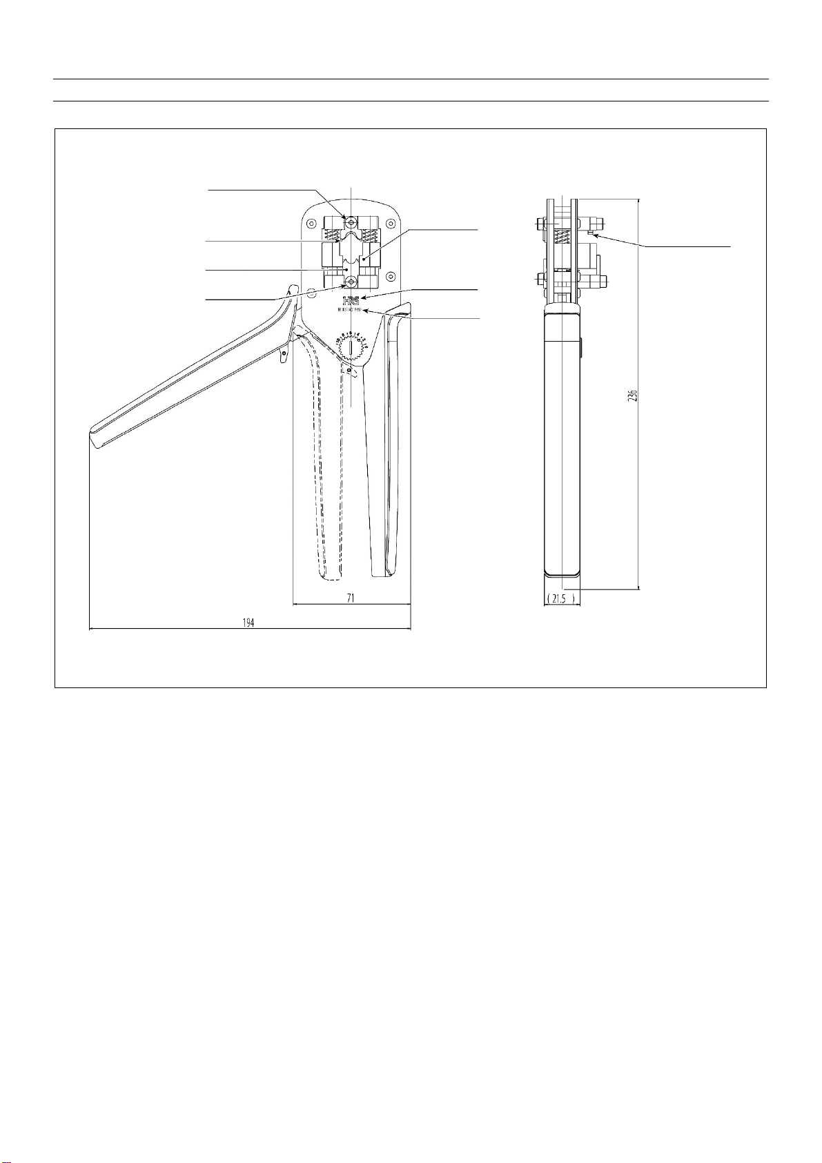
外形寸法/External dimensions 長さ 236㎜ × 幅71㎜ × 厚さ 21.5㎜
Length 236 mm × Width 71 mm × Thickness 21.5 mm
重量/Weight 1.0kg
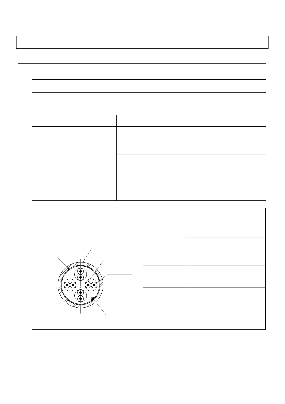
適合プラグ/Applicable plug
TM21P-88P(CL222-2862-9)
TM21CP-88P(CL222-2884-1-03)
TM21DP-TM-88P(CL222-2941-3)
TM31P-TM-88P(CL222-4626-7)
TM11AP-88P(CL222-2780-6)
TM36P-TM-88P※
TM21P-88P
適合ケーブル仕様/Applicable cable specifications
導体
Conductor
φ0.5㎜単線
ø 0.5 mm solid wire
AWG#24 より線
(φ0.2㎜×7本)
AWG #24 stranded wire
(ø 0.2 mm × 7 wires)
絶縁体外径
Insulator external
diameter
(φ0.9㎜ ~φ1.0㎜)
(ø 0.9 mm to ø 1.0 mm)
ドレイン線
Drain wire
AWG#26(すずコート線)
AWG #26 (Tin plated wire)
シース外径
Sheath external
diameter
(φ6.6mm)
※TM36P-TM-88P(CL222-4698-0)はTM36P-TM-88P(62)(CL222
-4698-0-6 2 )と TM36P-TM-88P(71)(CL222-4698-0-71)を一緒に
購入してください。
*For TM36P-TM-88P (CL222-4698-0), please purchased TM36P-TM-88P (62) (CL222-4698-0-62) and TM36P-
TM88P (71) (CL222-4698-0-71) together.
シールド
Shield
シース
Sheath
絶縁体
Insulator
導体
Conductor
ドレイン線
Drain wire
Apr.1.2022Copyright2022HIROSEELECTRICCO.,LTD.AllRightsReserved.

-
2
-
TM31P-TM-88P, TM36P-TM-88P
適合ケーブル仕様/Applicable cable specifications
導体
Conductor
AWG#24~#27 より線
AWG #24 to #27 stranded wire
絶縁体外径
Insulator external
diameter
(φ0.9㎜ ~φ1.0㎜)
(ø 0.9 mm to ø 1.0 mm)
遮蔽体
Shield material
すずめっき軟銅線編組シールド、
ラミネートテープ
Tinned annealed copper wire braid shield
,
Laminated tape
シース外径
Sheath external
diameter
(φ5.8㎜ ~φ6.0㎜)
(ø 5.8 mm to ø 6.0 mm)
TM11AP-88P
適合ケーブル仕様/Applicable cable specifications
導体
Conductor
AWG#26相当
Equivalent to AWG #26
絶縁体外径
Insulator external
diameter
(φ0.9㎜ ~φ1.0㎜)
(ø 0.9 mm to ø 1.0 mm)
シース外径
Sheath external
diameter
(φ5.0㎜)
導体
Conductor
絶縁体
Insulator
シース
Sheath
シールド
Shield
編組シールド
Braid shield
シース
Sheath
絶縁体
Insulator
導体
Conductor
電線シールド
Wires shield
Apr.1.2022Copyright2022HIROSEELECTRICCO.,LTD.AllRightsReserved.
Ყ㸱Ყ
Ძ
ᲫᲧᲭ φӲᢿƷӸᆅᲩ
Shape of tool and names of components
ǯȪȳ
ȑ
ܭƶ
ơ
Crimper fixing screw
ǯȪȳ
ȑ
Crimper
Ǣȳ
ȓ
ȫ
Anvil
Ǣȳ
ȓ
ȫ
ܭƶ
ơ
Anvil fixing screw
dz
ȍ
ǯǿțȫ
Ȁ
ȸ
Connector holder
*45 Ȟȸǯ
ᘙ
ᅆ
HRS marking
ᙌ
Լ
Ӹᘙ
ᅆ
Product name marking
ן
ȑ
ȳȁ
Insulation
dis
p
lacement
p
unch
Apr.1.2022Copyright2022HIROSEELECTRICCO.,LTD.AllRightsReserved.

Ყ㸲Ყ
ᇹ
ᇹᲬᇘ
˺ಅᲩ
CHAPTER 2 OPERATING PROCEDURE
ᲬᲧᲫ DZȸȖȫᇢϼྸᲩ
Cable end finish
Ĭ DZȸȖȫٳᘮǛኖᲭᲪəеᩉƠLJƢŵ
Ĭ Peel the cable sheath by approximately 30 mm.
ĭǷȸȫȉǛǷȸǹƷᇢ᩿ưǫȃȈƠLJƢŵ
ĭCut the shield at the end of the sheath.
ĮȝȪǨȁȬȳȆȸȗǛǷȸǹƷᇢ᩿ưǫȃȈƠLJ
Ƣŵ
ĮCut the polyethylene tape at the end of sheath.
ƂදƃٳᘮǛеᩉƢǔƴŴϋᢿƷӭዴǛ
ǭǺƭƚƳƍǑƏƴƠƯƘƩƞƍŵ
ǭǺƕλƬƨཞưƸŴ᎑ןɧᑣƳƲ
ƷҾ׆ƱƳǓLJƢŵ
[Caution] When peeling the sheath, be careful
not to damage the inside signal wire.
When the wire is damaged, defective
compression proofing or the like will
be caused.
Ƿȸȫȉ
Shield
Ƿȸǹ
Sheath
ȉȬǤȳዴ
Drain wire
ǷȸȫȉǫȃȈ
Shield cut
ə
ȝȪǨȁȬȳȆȸȗ
Polyethylene tape
ȝȪǨȁȬȳȆȸȗǫȃȈ
Pol
y
eth
y
lene ta
p
e cut
əˌɦᲩ1.5 mm or less
Apr.1.2022Copyright2022HIROSEELECTRICCO.,LTD.AllRightsReserved.

Ყ㸳Ყ
įȄǤǹȈȚǢᲧƷǑǓǛŴDZȸȖȫǷȸǹᇢ᩿LJ
ưDŽƙƠŴƠƝƍƯǯǻǛჼദƠLJƢŵ
ƜƷŴȉȬǤȳዴƸDZȸȖȫٳƴƛƯƓƍ
ƯƘƩƞƍŵ
įSlacken the twist of the twist pair up to the end of the
cable sheath and stretch to correct the way.
At this time, bend the drain wire on the outside of the
cable.
İDZȸȖȫᑵዴǛŴఌΨƔǒdzȍǯǿƷȔȳǢǵǤ
ȳƷဪƴ્ݧཞƴ࠼ƛƯƘƩƞƍŵ
İ Spread out the cable contact wires from the root in all
directions in the order of the pin assignment of the
connector.
ıDZȸȖȫᑵዴǛŴȔȳǢǵǤȳƴࢼƍૢЗƞƤƯ
ƘƩƞƍŵ
ıLine up the cable contact wires in accordance with the
pin assignment.
ƂදƃȄǤǹȈȚǢᲧƷǑǓƷჼദƕҗЎư
ƳƍƱŴࢸᆉưƷ˺ಅƕᩊƠƘƳǓ
LJƢŵDZȸȖȫᑵዴƸᄩܱƴDŽƙƠƯ
ƓƍƯƘƩƞƍŵ
[Caution] When the correction of the twist of the
twist pair is not sufficient, the work of
the post-process will be difficult. So
securely slacken the cable contact
wires.
ƂදƃDZȸȖȫᑵዴǛ࠼ƛǔƸŴᑵዴӷٟ
ƕʩࠀƠƳƍǑƏƴƠƯƘƩƞƍŵ
ᑵዴӷٟƕʩࠀƠƨLJLJƷཞưƸŴ
ࢸᆉưǬǤȉȗȬȸȈƕ٭࢟Ƣǔ
ǕƕƋǓLJƢŵ
[Caution] When spreading out the cable contact
wires, be careful not to allow the
contact wires to intersect with one
another.
When they are intersected with one
another, the guide plate may be
deformed at the post-process.
ȉȬǤȳዴ
Drain wire
Apr.1.2022Copyright2022HIROSEELECTRICCO.,LTD.AllRightsReserved.

Ყ㸴Ყ
IJǬǤȉȗȬȸȈǛλǕǍƢƘƢǔƨNJƴŴDZȸȖ
ȫᑵዴƷέᇢǛȋȃȑȸƳƲưЏǓƑƯƘƩƞ
ƍŵ
IJCut and arrange the top ends of the cable contact wires
with nippers or the like so that the guide plate can be
easily placed.
ijǬǤȉȗȬȸȈǛǷȸǹᇢ᩿ƔǒᲭ᳸ᲯəƷˮፗ
LJưλƠƯƘƩƞƍŵ
ƜƷŴλǕǍƢƘƢǔƨNJƴDZȸȖȫᑵዴƷέ
ᇢǛȋȃȑȸƳƲưЏǓƑƯƘƩƞƍŵ
ijInsert the guide plate into the position of 3 to 5 mm
from the end of the sheath.
At this time, cut and arrange the top ends of the cable
contact wires with nippers or the like so that the guide
plate can be easily placed.
ĴDZȸȖȫǷȸǹǛǬǤȉȗȬȸȈƔǒ d əƷ
ˮፗLJưеᩉƠƯƘƩƞƍŵ
ƜƷᨥŴǷȸȫȉƸЏǒƣƴസƠƯƓƍƯƘƩƞ
ƍŵ
ĴPeel the cable sheath up to the place of 14±1 mm from
the guide plate.
At this time, leave the shield without cutting.
ĵDZȸȖȫᑵዴǛǬǤȉȗȬȸȈƷέᇢƔǒኖ
əƷˮፗưЏǓƑƯƘƩƞƍŵ
ĵCut and arrange the cable contact wires at the position
of approximately 0.5 mm from the top end of the guide
plate.
ƂදƃDZȸȖȫᑵዴǛᡫƢƜƱƴǑƬƯǬǤ
ȉȗȬȸȈƕ٭࢟ƠƳƍǑƏƴƠƯƘ
Ʃƞƍŵ
ǬǤȉȗȬȸȈƕ٭࢟ƢǔᨥƸŴϐࡇ
ᑵዴƷȕǩȸȟȳǰǛǍǓႺƠƯƘƩ
ƞƍŵ
[Caution] Be careful not to allow the guide plate
to be deformed by passing the cable
contact wires.
When the guide plate is deformed,
perform again the forming of the
contact wires.
έᇢЏǓƑ
Cut and arrange
the top ends.
ǬǤȉȗȬȸȈ
Guide plate
᳸ə
3 to 5 mm
ǬǤȉȗȬȸȈƷ٭࢟
Deformation of guide plate
Ƿȸȫȉ
Shield
έᇢЏǓƑ
Cut and arrange
the top ends.
Apr.1.2022Copyright2022HIROSEELECTRICCO.,LTD.AllRightsReserved.

Ყ㸵Ყ
Ķኖ əƷȆȸȗǛDZȸȖȫƷǷȸǹƴ ԗ
ࠇƍƯƘƩƞƍŵ
ȆȸȗƷᧈƞƸŴDZȸȖȫƴࠇƖƭƚƨཞư
ٳࢲƕኖ əƴƳǔᧈƞǛؕแƱƠƯƘƩƞ
ƍŵ
ᲢӋᎋᲴ ƷDZȸȖȫƷئӳ əưƢŵᲣ
ĶTurn the copper tape of approximately 12.7 mm wide
once around the sheath of the cable.
For the length of the copper tape, make as the standard
the length that the external diameter is approximately
6.8 mm in the state that it is turned around the cable.
(Reference : In case of ø6.5 cable, the length is 32 mm.)
ķȉȬǤȳዴƕȆȸȗƷࠢƴλǔǑƏƴȕǩȸȟ
ȳǰƠƯƘƩƞƍŵ
ķPerform forming so that the drain wire enters the width
of the copper tape.
ĸസǓƷȆȸȗǛࠇƖƭƚƯƘƩƞƍŵ
ĸTurn the remaining copper tape around the sheath.
Ȇȸȗ
Copper tape
ƷǓᲩGlue side
Ƿȸǹᇢ᩿
End of sheath
ȉȬǤȳዴȕǩȸȟȳǰ
Forming of drain wire
Apr.1.2022Copyright2022HIROSEELECTRICCO.,LTD.AllRightsReserved.

Ყ㸶Ყ
Ĺdzȍǯǿஜ˳ƷDZȸȖȫǯȩȳȗᢿƴ࢘ƨǒƳƍ
ǑƏƴŴNJɥ૾ӼƔǒDZȸȖȫǛλƠLJƢŵ
ǬǤȉȗȬȸȈƷέᇢƕdzȍǯǿஜ˳ƷɶƴλƬ
ƨǒŴDZȸȖȫέᇢᢿƕdzȍǯǿஜ˳ϋᢿƷ࢘ƨ
ǔLJưλƠƯƘƩƞƍŵ
ĹInsert the cable from the upper aslant direction so that it
does not come in contact with the cable clamp section of
the connector main unit.
When the top end of the guide plate has entered in the
connector main unit, insert it to the position where the
top end section of the cable comes in contact with the
inside of the connector main unit.
DZȸȖȫᑵዴέᇢƕ࢘ƨǔLJưƢ
Press up to the place where the top end of
the cable contact wire comes in contact
with the inside.
ǯȩȳȗᢿ
Clamp section
Apr.1.2022Copyright2022HIROSEELECTRICCO.,LTD.AllRightsReserved.
-
9
-
2-2. クリンパ・アンビルの取り付け/Installing crimper and anvil
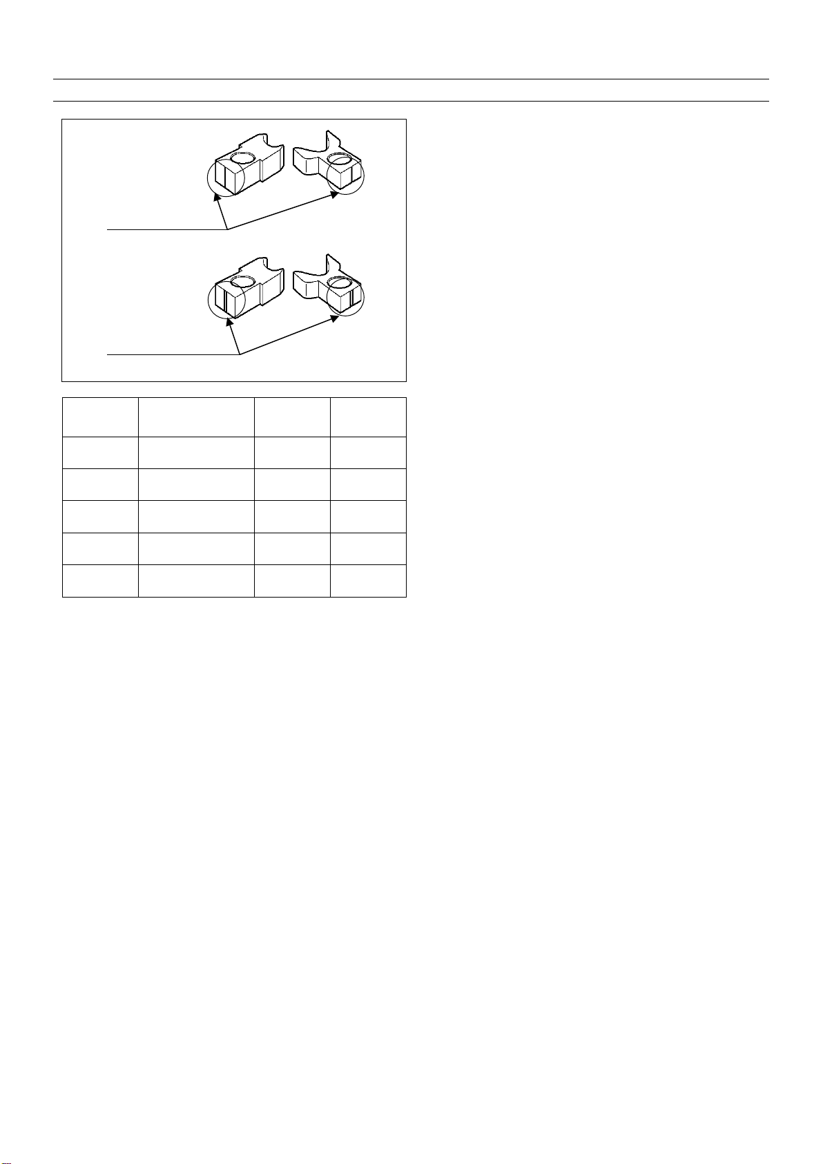
① 本工具にはクリンパ・アンビルが2個ずつ添付さ
れています。
各々に線が1本、または2本付いています。
下表に従って、正しい組み合わせを選んでくださ
い。
①Two pieces each of crimper and anvil are provided with
this tool.
One or two wires are provided with each.
Select the proper combination following the table below.
ケーブル径
Cable diameter
クリンパ
Crimper
アンビル
Anvil
TM11 φ5.5 ㎜I I
TM11 φ6.5 ㎜I I I I
TM21 I I I I
TM31 I I
TM36 I I
識別線
Discrimination line
識別線
Discrimination line
Apr.1.2022Copyright2022HIROSEELECTRICCO.,LTD.AllRightsReserved.

Ყ㸯㸮Ყ
Წ
ᲬᲧᲭ ኽዴ˺ಅᲩ
Wire connecting operation
Ĭ᳂ᲰᲪᲭᲩ᳇ᲬᲫᲧᲲᲲƷȏȳȉȫǛ
ɟࡇơƯŴȩȁǧȃȈǛᚐᨊƠƯƔǒஇٻƴ
ƍƯƘƩƞƍŵ
ĭφƷλӝƴdzȍǯǿǛλƠŴDZȸȖȫǛჵ
ҮƷ૾ӼƴƠƳƕǒȏȳȉȫǛƬƯƘƩƞ
ƍŵ
Ĭ Open the handle of HT603/TM-21P-88P to the
maximum after closing once and releasing the ratchet.
ĭ Insert the connector into the insertion opening of the
tool and hold the handle while pushing the cable in the
direction of the arrow.
ĮȩȁǧȃȈƕƖǕǔLJưȏȳȉȫǛƬƯኽዴ
ǛᘍƍLJƢŵ
ĮHold the handle up to the position where the ratchet is
released and perform the wire connecting operation.
ƂදƃλƷᨥŴdzȍǯǿƷӼƖǛ᧓ᢌƑƳ
ƍǑƏƴදƠƯƘƩƞƍ
ŵ
dzȍǯǿƕǹȈȃȑȸƴ࢘ƨƬƯƍǔ
ཞǛᄩᛐƠƯƘƩƞƍ
[Caution] When inserting, be careful not to
mistake the direction of the connector.
Check that the connector is in contact
with the stopper.
ƂදƃdzȍǯǿǛןƢǔᨥƸŴdzȍǯǿƕ
țȫȀȸƴݣƠƯŴӫƴǔǑƏƳ
ᒵƕƔƔǒƳƍǑƏƴƠƯ
ƘƩƞ
[Caution] When performing the insulation
displacement of the connector, be
careful not to apply any load inclining
to the right or left to the connector in
terms of the holder.
Apr.1.2022Copyright2022HIROSEELECTRICCO.,LTD.AllRightsReserved.

Ყ㸯㸯Ყ
Წ
ᲬᲧᲮ ԼឋؕแᲩ
Quality standard
ןࢸƷdzȍǯǿƕɦᚡƷᙹǛឱƠƯƍǔƜƱǛᄩ
ᛐƠƯƘƩƞƍŵ
Ĭ ᑵዴƷέᇢƕȗȩǰƷُƴᚑƠƯƍǔƜƱŵ
ĭ ǬǤȉȗȬȸȈέᇢƕǹȈȃȑȸᢿLJưƠᡂLJǕ
ƯƍǔƜƱŵ
Į ןȏǤȈƕŴᲰᲪᲬdᲪᲫəƷƜƱŵ
į DZȸȖȫьዸNJȏǤȈƕᲰᲯ᳸ᲰᲳəưƋǔƜƱŵ
İ ǰȩȳȉெƷ৵ǓƛᚌࡇƕᲮᲯcˌɥưƋǔƜƱŵ
Confirm that the connector after the insulation displacement
satisfies the standard below.
Ĭ The top end of the contact wire comes in contact with the
wall of the plug.
ĭ The top end of the guide plate is pressed up to the
stopper section.
Į Insulation displacement height has to be 6.02 ± 0.1 mm.
į Cable caulking height has to be 6.5 to 6.9 mm.
İ The bending angle of the ground plate has to be 45° or
more.
ĭǬǤȉȗȬȸȈέᇢˮፗ
Top end position of guide plate
Ĭᑵዴέᇢƕُƴᚑ
Top end of contact wire comes in contact
with wall.
İ৵Ǔƛᚌࡇ
Bending angle
įьዸNJȏǤȈ
Caulking height
ĮןȏǤȈ
Insulation displacement height
Apr.1.2022Copyright2022HIROSEELECTRICCO.,LTD.AllRightsReserved.

Ყ㸯㸰Ყ
ᇹ
ᇹᲭᇘ
ܣƱໜ౨Ჩ
CHAPTER 3 MAINTENANCE AND INSPECTION
ᲭᲧᲫ ӕǓৢƍɥƷදʙᲩ
Matters that demand special attention when handling
ĬφǛӡƍƨǓŴ᭗ƍƔǒᓳƱƢƳƲƷᘔએƸŴዌݣьƑƳƍưƘƩƞƍŵ
ĭஜƴᅆƢᢘӳdzȍǯǿ֫ᢘӳDZȸȖȫˌٳƷNjƷǛዌݣƴןƠƳƍưƘƩƞƍŵ
ĮȩȁǧȃȈƕᚐᨊƢǔЭƴȏȳȉȫǛƘƜƱƸưƖLJƤǜŵ
įφƴɧφӳƕႆဃƠƨƸŴᚐ˳ƳƲƤƣƦƷLJLJƷཞưɧφӳϋܾǛଢᅆƷɥŴࡴᅈƴ
ƓဎƠ˄ƚƘƩƞƍŵ
ĬNever apply shocks such as tapping, dropping the tool from a high place, etc.
ĭNever perform insulation displacement of anything other than the applicable connector and applicable cable described
in this Manual.
ĮHandle cannot be opened before the ratchet is released.
įWhen trouble of the tool occurs, contact our office while informing us of the trouble state and leaving the tool as it is
without disassembling.
ᲭᲧᲬ ଐࠝƷƓλǕƴƭƍƯᲩ
Daily maintenance
Ĭ˺ಅƕኳʕƠƨئӳƸŴțdzȪᲦǴȟᲦ൦ЎƳƲǛŴ௩ǒƔƍࠋƳƲưฌƠƯƘƩƞƍŵ
ĭȏȳȉȫƷᨥŴȏȳȉȫƕǫǸȪƳƲƳƘ๖ǒƔƴѣƢǔƜƱǛᄩᛐƠƯƘƩƞƍŵ
ƂදƃțdzȪᲦǴȟƳƲƕφƴ˄ბƠLJƢƱŴᢘദƳןƕưƖƳƘƳǓLJƢŵLJƨŴƦǕǒƷီཋƕ
dz
dzȍǯǿƴ˄ბƢǔǕƕƋǓLJƢŵ
ĬWhen the work has been completed, wipe dirt, dust, moisture, etc. with a piece of soft cloth.
ĭWhen opening/closing the handle, check that the handle smoothly moves without galling or the like.
[Caution] When dirt, dust, etc. adhere to the jig, the proper insulation displacement cannot be performed.
In addition, those foreign matters may adhere to the connector.
Apr.1.2022Copyright2022HIROSEELECTRICCO.,LTD.AllRightsReserved.

Apr.1.2022Copyright2022HIROSEELECTRICCO.,LTD.AllRightsReserved.

Apr.1.2022Copyright2022HIROSEELECTRICCO.,LTD.AllRightsReserved.

Ȓȭǻᩓೞఇࡸ˟ᅈ
HIROSE ELECTRIC CO., LTD. 2021
ӕৢᛟଢဪӭ Instruction Manual Number
è6#&2 èTAD-P0395
ႆᘍ࠰உ ࠰ 4 உDate of issue April 2021
ોܭ࠰உ Date of revision
༿ૠ И ༿Edition number First edition
ᲢᲫᲣ ஜƷɟᢿLJƨƸμᢿǛૺ᠃᠍ƢǔƜƱƸƘƓૺǓᐲƠLJƢŵ
ᲢᲬᲣ ஜƷϋܾƴƭƍƯŴݩஹʖԓƳƠƴ٭ƢǔƜƱƕƋǓLJƢŵ
ᲢᲭᲣ ஜƷϋܾƴƭƖLJƠƯƸŴɢμǛƠƯ˺ᐲƠLJƠƨƕŴɢɟƝɧݙƳໜǍᛚǓŴᚡ᠍ǕƳ
ƲŴƓൢ˄ƖƷໜƕƝƟƍLJƠƨǒӲૅࡃŴփಅLJưƝᡲዂƘƩƞƍŵ
ᲢᲮᲣ ࢘ᅈưƸŴஜᙌԼƷᢃဇǛྸဌƱƢǔڂŴڂМႩƳƲƷᛪ൭ƴƭƖLJƠƯƸŴᲢᲭᲣƴƔƔ
ǘǒƣᝧ˓ǛƍψƶLJƢƷưƝʕ১ƘƩƞƍŵ
ᲢᲯᲣ ஜᙌԼƕƓܲಮƴǑǓɧᢘЏƴဇƞǕƨǓŴஜƷϋܾƴࢼǘƣƴӕǓৢǘǕƨǓŴLJƨƸȒȭ
ǻᩓೞఇࡸ˟ᅈˌٳƷᇹɤᎍƴǑǓྸŴ٭ƞǕƨƜƱƳƲƴឪ׆ƠƯဃơƨܹƳƲƴƭƖ
LJƠƯƸŴᝧ˓ǛƍψƶLJƢƷưƝʕ১ƘƩƞƍŵ
ᲢᲰᲣ ෙٳƴƓƍƯƸŴஜᙌԼƷܣŴྸݣࣖǛƠƯƓǓLJƤǜƷưƝ১ჷƘƩƞƍŵ
ද
(1) No part of this manual may be reproduced without the permission of Hirose Electric Co., Ltd.
(2) Description in this manual is subject to change without notice.
(3) This Instruction Manual has been prepared for clarify. Should you find any unclear portion,
error, or omission, please, for the safety of other, contact our Marketing Department.
(4) It should be understood that, not withstanding the aforementioned item (3), we assume no
liability to any claim for loss or failure to earn profit resulting from the use of the machine.
(5) We assume no responsibility for any damage resulting from your improper use of the machine
including your failure to follow the instructions given in this Instruction Manual. This includes
repair or modification conducted by any third party other than Hirose Electric Co., Ltd.
(6) Please note that servicing of the machine is not available in any country other than Japan.
CAUTION
Apr.1.2022Copyright2022HIROSEELECTRICCO.,LTD.AllRightsReserved.

21.04Printed in Japan
ஜᅈƄ ᅕډ߷Ⴤ್ාࠊᣃሇғɶ߷ɶځʚɠႸ ဪ ӭ
ƝɧଢƳໜƳƲƝƟƍLJƠƨǒ
࢘փಅLJƨƸ 9'$ ǵǤȈƔǒƓբƍӳǘƤƘƩƞƍŵ
JVVRUYYYJKTQUGEQO
6-3, NAKAGAWACHUO 2-CHOME, TSUZUKI-KU, YOKOHAMA-SHI,
KANAGAWA 224-8540, JAPAN
https://www.hirose.com
Apr.1.2022Copyright2022HIROSEELECTRICCO.,LTD.AllRightsReserved.
Table of contents
Other Hirose Tools manuals

/CK-MP User manual")
Popular Tools manuals by other brands


RAASM
RAASM s. 430 S manual

Samoa
Samoa 168 600 Parts and technical service guide

Grant's
Grant's 57317 Owner's manual & safety instructions

Parkside
Parkside PDST 10 B3 Translation of the original instructions

Gude
Gude Automatic hose reel 15M Translation of the original instructions

Fohrenbach
Fohrenbach HT129 user guide


