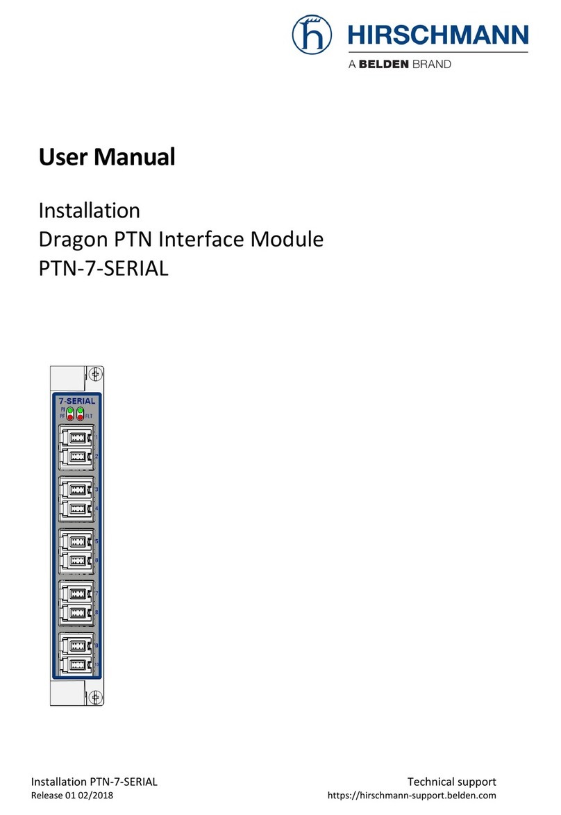
Installation PTN-4-DSL-LW 3
Release 01 02/2018
Contents
1. INTRODUCTION ......................................................................................................... 5
1.1 General...............................................................................................5
1.2 Manual References .............................................................................6
2. MODULE DESCRIPTION .............................................................................................. 7
2.1 Front Panel .........................................................................................7
2.1.1 Handle........................................................................................................7
2.1.2 LEDs............................................................................................................7
2.1.3 SHDSL RJ-45 Ports and Cables ...................................................................8
2.2 Functional Operation ..........................................................................9
2.2.1 Device Mode: CO/CPE ...............................................................................9
2.2.2 SHDSL Link Bring Up.................................................................................10
2.2.3 PAF or Bonding ........................................................................................10
2.2.4 Ethernet Service ......................................................................................11
2.2.5 SHDSL Bandwidth and Distances .............................................................12
2.2.6 I/O with the Central Switching Module (=CSM) ......................................12
2.2.7 Synchronization / Clock Distribution / Network Timing..........................13
2.2.8 Ethernet First Mile –Copper (=EFM-C) (currently not supported) .........13
2.2.9 Wetting Current (currently not supported) ............................................13
2.2.10 Loopback Selftests ...................................................................................14
2.3 Onboard Interfaces ...........................................................................14
2.3.1 Straps .......................................................................................................14
2.3.2 DIP Switches ............................................................................................14
3. MODULE SPECIFICATIONS ........................................................................................ 16
3.1 General Specifications....................................................................... 16
3.2 Other Specificiations......................................................................... 16
3.3 Ordering Information........................................................................ 16
4. ABBREVIATIONS ...................................................................................................... 16
List of figures
Figure 1 General SHDSL Example .................................................................................................. 6
Figure 2 Front Panel ...................................................................................................................... 7
Figure 3 SHDSL RJ-45 Connector ................................................................................................... 8
Figure 4 Detailed Functional Setup ............................................................................................... 9
Figure 5 Basic PAM Encoding ...................................................................................................... 12
Figure 6 4-DSL-LW: Side View...................................................................................................... 14
Figure 7 Hardware Edition........................................................................................................... 15
Figure 8 Device Mode Configuration........................................................................................... 15


