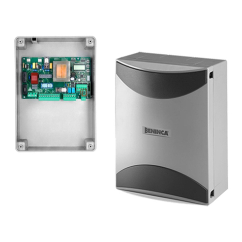
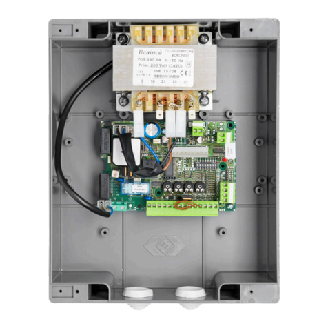
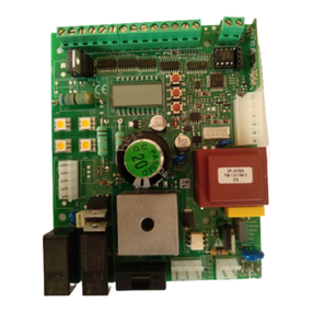
Beninca BRAINY User manual

UNIONE NAZIONALE COSTRUTTORI
AUTOMATISMI PER CANCELLI, PORTE
SERRANDE ED AFFINI
BRAINY
IT
EN
DE
FR
ES
PL
L8542910
07/2019 rev. 6

2
111098765 13124
33323130292827 3534 3626252423222120
F2
115/230Vac
50/60Hz
N
GND L
RADIO
TLS
Encoder M1
24Vac
500mA max
AUX1
AUX2
COM
M1
C
COM
M2
C
M1
191817161514
3837
NL
F1
LAMP
230Vac
Encoder M2
M2
Lock
12Vdc
10W
J2 DAS
Open
DAS N.C.
J2 DAS
Close
DAS 8K2
DAS
Encoder M1
M1
+ s -
Encoder M2
M2
+ s -
3+3 x 0.5mm
2
max 10m
U11
33323130292827 3534 3626252423222120
8k2
DAS
SWO-M1 (Open)
SWC-M1 (Close)
SWO-M2 (Open)
SWC-M2 (Close)
P.P.
COM
COM
PED.
OPEN
CLOSE
PHOT
PHOT (Close)
STOP
SHIELD
ANT
ANT
____
Code
Fig. 1

3
Fig. 2
SCA 24Vac
3W max
24Vac
1A max
191817161514 191817161514 31 32 3331292827 31 32 3331292827
24Vac 24Vac
COM
NC NO
RX1TX1
SCA PHOTO-TEST
191817161514
24Vac 24Vac
COM
NC NO
RX2TX2
24 25 2623222120
OPEN/CLOSE CLOSE
191817161514
BAR-TEST
BZ
LD1
N.C. N.C.
12-24
OPEN
BZ-W1-W2
CLOSE
DEFAULT
12/24
W2
W1
CH1 CH2 12/24V TSTANT
P
ANT
SHIELD
1
NOT
USED
2 3
(-)
4
(+)
J2 DAS
Open
DAS N.C.
J2 DAS
Close
DAS 8K2
S1
J1
LED 2
J2
RF.+ SUN PANEL
J1 Close
RF
J1 Open
SC-RF
RF

4
v1.05
8888
on PRG PUSH OK
PUSH OK
rtr PRG OK
PUSH OK
PUSH OK
LOG
RADI
TCA
tca
pp
clr
rtr
2ch
ped
0000 conf OK
res PRG
OFF PRG
0012 3456
Nman
MACI
RES
CODE
par
9000 9C5a
AUTO OK
PUSH
TCA
LOG radi
PAR
Power ON
Display OFF
pp
RE-ENTER
CODE
Display OFF
N Cycle
OPEN/CLOSE
Firmware Ver. (3s)
Diagnostic PRG
tca 40
OFF PRG
ibl
OFF PRG
IBCA
OFF PRG
SCl
OFF PRG
PP
OFF PRG
PRE
OFF PRG
HAM
OFF PRG
blc
OFF PRG
spn
OFF PRG
ltca
OFF PRG
htr
OFF PRG
1mot
OFF PRG
enc
on PRG
cvar
OFF PRG
mloc
OFF PRG
trx
OFF PRG
tst1
OFF PRG
tst2
OFF PRG
tst3
OFF PRG
2ch
OFF PRG
bb
OFF PRG
horn
ON PRG
REM
PRG
tm1 24
PRG
tm2 24
PRG
tped 50
PRG
PMO1 40
PRG
PMC1 40
PRG
PMO2 40
PRG
PMC2 40
PRG
tdmo 2
PRG
tdmc 3
PRG
tls 60
PRG
tloc 3
PRG
TSM1 0
PRG
TSM2 0
PRG
Pso1 70
PRG
PSc1 70
PRG
PSO2 70
PRG
PSC2 70
PRG
SEAU 0
PRG
SEAR 0
PRG
TINC 250
PRG
BLCC 0
PRG
BLCO 0

5
Schema menu di programmazione - Menu programming layout
Diagramm Programmiermenü - Menu de programmation
Menú de la carta de programación - Układ menu programowania
v1.05
8888
on PRG PUSH OK
PUSH OK
rtr PRG OK
PUSH OK
PUSH OK
LOG
RADI
TCA
tca
pp
clr
rtr
2ch
ped
0000 conf OK
res PRG
OFF PRG
0012 3456
Nman
MACI
RES
CODE
par
9000 9C5a
AUTO OK
PUSH
TCA
LOG radi
PAR
Power ON
Display OFF
pp
RE-ENTER
CODE
Display OFF
N Cycle
OPEN/CLOSE
Firmware Ver. (3s)
Diagnostic PRG
tca 40
OFF PRG
ibl
OFF PRG
IBCA
OFF PRG
SCl
OFF PRG
PP
OFF PRG
PRE
OFF PRG
HAM
OFF PRG
blc
OFF PRG
spn
OFF PRG
ltca
OFF PRG
htr
OFF PRG
1mot
OFF PRG
enc
on PRG
cvar
OFF PRG
mloc
OFF PRG
trx
OFF PRG
tst1
OFF PRG
tst2
OFF PRG
tst3
OFF PRG
2ch
OFF PRG
bb
OFF PRG
horn
ON PRG
REM
PRG
tm1 24
PRG
tm2 24
PRG
tped 50
PRG
PMO1 40
PRG
PMC1 40
PRG
PMO2 40
PRG
PMC2 40
PRG
tdmo 2
PRG
tdmc 3
PRG
tls 60
PRG
tloc 3
PRG
TSM1 0
PRG
TSM2 0
PRG
Pso1 70
PRG
PSc1 70
PRG
PSO2 70
PRG
PSC2 70
PRG
SEAU 0
PRG
SEAR 0
PRG
TINC 250
PRG
BLCC 0
PRG
BLCO 0
Legenda
Premere il tasto (-) / Press key (-) / Die Taste (-) drücken
Appuyez sur la touche (-) / Presionar la tecla (-) / Wcisnąć przycisk (-)
Premere il tasto (+) / Press key (+) / Die Taste (+) drücken
Appuyez sur la touche (+) / Presionar la tecla (+) / Wcisnąć przycisk (+)
Premere il tasto (PG) / Press key (PG) / Die Taste (PG) drücken
Appuyez sur la touche (PG) / Presionar la tecla (PG )/ Wcisnąć przycisk (PG)
Premere simultaneamente (+) e (-) / Press simultaneously keys (+) and (-)
Gleichzeitig (+) und (-) drücken / Presser simultanément (+) et (-)
Presionar simultáneamente (+) y (-) / Naciskać jednocześnie (+) i (-)
Selezionare il valore desiderato con i pulsanti (+) e (-)
Increase/decrease the value with keys (+) and (-)
Mit den Tasten (+) und (-) kann man eingerichtete Werte ändern
Régler la valeur désirée avec les touches (+) et (-)
Establecer con las teclas (+) y (-) el valor deseado
Nastawia przyciskami (+) i (-) obraną wartoś
Selezionare il pulsante del trasmettitore da associare alla funzione
Press the transmitter key, which is to be assigned to function
Taste des Sendegeräts drücken, dem diese Funktion zugeteilt werden soll.
Appuyer sur la touche du transmetteur qu’e l’on désire affecter à cette fonction.
Presionar la tecla del transmisor que se desea asignar a esta función.
Wcisnąć przycisk nadajnika, który zamierza się skojarzyć z tą funkcją.

14
ENG WARNING
The product shall not be used for purposes or in ways other than those for which the product is intended for and as described in
this manual. Incorrect uses can damage the product and cause injuries and damages.
The company shall not be deemed responsible for the non-compliance with a good manufacture technique of gates as well as for
any deformation, which might occur during use.
Keep this manual for further use.
This manual has been especially written to be use by qualified fitters.
Installation must be carried out by qualified personnel (professional installer, according to EN 12635), in compliance with Good
Practice and current code.
Make sure that the structure of the gate is suitable for automation.
The installer must supply all information on the automatic, manual and emergency operation of the automatic system and supply
the end user with instructions for use.
Packaging must be kept out of reach of children, as it can be hazardous. For disposal, packaging must be divided the various types
of waste (e.g. carton board, polystyrene) in compliance with regulations in force.
Do not allow children to play with the fixed control devices of the product. Keep the remote controls out of reach of children.
This product is not to be used by persons (including children) with reduced physical, sensory or mental capacity, or who are unfa-
miliar with such equipment, unless under the supervision of or following training by persons responsible for their safety.
Apply all safety devices (photocells, safety edges, etc.) required to keep the area free of impact, crushing, dragging and shearing
hazard. Bear in mind the standards and directives in force, Good Practice criteria, intended use, the installation environment, the
operating logic of the system and forces generated by the automated system.
Installation must be carried out using safety devices and controls that meet standards EN 12978 and EN 12453.
Only use original accessories and spare parts, use of non-original spare parts will cause the warranty planned to cover the products
to become null and void.
All the mechanical and electrical parts composing automation must meet the requirements of the standards in force and outlined
by CE marking.
An omnipolar switch/section switch with remote contact opening equal to, or higher than 3mm must be provided on the power
supply mains.
Make sure that before wiring an adequate differential switch and an overcurrent protection is provided.
Pursuant to safety regulations in force, some types of installation require that the gate connection be earthed.
During installation, maintenance and repair, cut off power supply before accessing to live parts.
Also disconnect buffer batteries, if any are connected.
The electrical installation and the operating logic must comply with the regulations in force.
The leads fed with different voltages must be physically separate, or they must be suitably insulated with additional insulation of
at least 1 mm.
The leads must be secured with an additional fixture near the terminals.
During installation, maintenance and repair, interrupt the power supply before opening the lid to access the electrical parts
Check all the connections again before switching on the power.
The unused N.C. inputs must be bridged.
WASTE DISPOSAL
As indicated by the symbol shown, it is forbidden to dispose this product as normal urban waste as some parts might be harmful
for environment and human health, if they are disposed of incorrectly. Therefore, the device should be disposed in special collec-
tion platforms or given back to the reseller if a new and similar device is purchased. An incorrect disposal of the device will result
in fines applied to the user, as provided for by regulations in force.
Descriptions and figures in this manual are not binding. While leaving the essential characteristics of the product unchanged, the manufac-
turer reserves the right to modify the same under the technical, design or commercial point of view without necessarily update this manual.

15
EN
BRAINY CONTROL UNIT
INPUT/OUTPUT FUNCTIONS
N° Terminals Function Description
1-2-3 Power supply Input 230 Vac ±10% 50/60Hz (1-GND/2-Phase/3-Neutral)
4-5-6 Motor 1 Connection of motor 1: (4-start/5-Com/6-start)
7-8-9 Motor 2 Connection of motor 2: (7-start/8-Com/9-start)
10-11 Blinking light Connection of blinking light 230Vac 40W max.
12-13 TLS N.O. clean contact (230V/16A max) for courtesy light, timer, etc.
The activation time is regulated by the parameter TLS
14-15 24 Vac Accessories power supply output 24Vac/1A max.
16-17 Lock 12Vdc Accessories power supply output 12Vac/10W for electric lock (16:0V, 17:+12V)
18-19 AUX1 Normally Open clean contact, configurable as SCA- open gate light (default) or photocell test.
20-21 EDGE
Input, sensitive edge contact
Resistive edge: “DAS” Jumper closed
Mechanical edge: “DAS” Jumper open
When the edge is activated, the gate movement is stopped and reversed for about 3s.
22 SWO-M1 OPEN limit switch input motor 1 (N.C contact.)
23 SWC-M1 CLOSE limit switch input motor 1 (N.C. contact)
24 SWO-M2 OPEN limit switch input motor 2 (N.C. contact)
25 SWC-M2 CLOSE limit switch input motor 2 (N.C. contact)
26-27 COM Common for limit switch and all the control inputs.
28 Step-by-Step Step-by-Step button input (N.O. contact)
29 PED Pedestrian button input (N.O. contact)
30 OPEN Input, OPEN push-button (Normally open contact).
It is possible to connect a timer for opening in time slots.
31 CLOSE CLOSE button input (N.O. contact)
32 PHOT Active photocell input on opening and closing
33 PHOT CLOSE Active photocell input only on closing
34 STOP STOP button input (N.C. contact)
35-36 Antenna
Antenna connection for plug-in radio receiver board (35-screen/36-signal).
37-38 AUX2 Voltage-free Normally Open Contact. Configurable as second radio channel (default) or SCA-
open gate LED.
J3 Radio Plug-in connector for radio receiver.
The control unit is equipped with an built-in radio module for the reception of variable code controls, with ARC (Advanced Rolling-
Code) or fixed code, 433.92 MHz frequency.
NOTES
The EDGE must be connected exclusively to the special inputs 20/21. Two types of EDGE may be used:
If an edge with resistance 8K2 is used, close the Jumper “DAS”.
If a mechanical edge with N.C. contact is used, open the Jumper “DAS”.
If the edge is not used, bridge the terminals 20-21 and open the Jumper “DAS”.
TO CHECK CONNECTIONS:
1) Cut-off power supply.
2) Manually release the wings, move them to approx. half-stroke and lock them again.
3) Reset power supply.
4) Send a step-by-step control signal by pressing the button or the remote control key.
5) The wings should start an opening movement.
If this is not the case, invert the movement wires of the motor. (4<>6 for motor M1, and 7<>9 for motor M2) and the relevant limit
switch inputs (22<>23 for motor M1, and 24<>25 for motor M2).
ARC COMPATIBLE CONTROL UNIT
IMPORTANT, PLEASE READ CAREFULLY:
The radio receiver in this product is compatible with the new ARC (Advanced Rolling Code) transmitters which, thanks to 128-bit en-
cryption ensure superior copy-security.
Storing new ARC transmitters is quite similar to that of normal rolling code transmitters with HCS coding, but be aware that:
1) ARC transmitters and Rolling Code HCS can not be stored in a single receiver.
2) The first transmitter memorized determines the type of transmitters to be used later. If the first transmitter memorized is ARC, you can
not store Rolling code HCS transmitters, and vice versa.
16
3) Fixed code transmitters may only be used in conjunction with Rolling code HCS transmitters, bringing the logic CVAR OFF. They are,
therefore, not usable in combination with the ARC transmitters. If the first rolling code transmitter stored is an ARC CVAR the logic is
inoperative.
4) If you want to change the type of transmitters it is necessary to proceed with a receiver reset.
PROGRAMMING
The programming of the various functions of the control unit is carried out using the LCD display on the control unit and setting the
desired values in the programming menus described below.
The parameters menu allows you to assign a numerical value to a function, in the same way as a regulating trimmer.
The logic menu allows you to activate or deactivate a function, in the same way as setting a dip-switch.
Other special functions follow the parameters and logic menus and may vary depending on the type of control unit or the software
release.
TO ACCESS PROGRAMMING
1 – Press the button <PG>, the display goes to the first menu, Parameters “PAR”.
2 – With the <+> or <-> button, select the menu you want.
3- Press the button <PG>, the display shows the first function available on the menu.
4 - With the <+> or <-> button, select the function you want.
5 - Press the button <PG>, the display shows the value currently set for the function selected.
6 - With the <+> or <-> button, select the value you intend to assign to the function.
7 - Press the button <PG>, the display shows the signal “PRG” which indicates that programming has been completed.
NOTES
Pressing <-> with the display turned off means an impulse of P.P.
Simultaneously pressing <+> and <-> from inside a function menu allows you to return to the previous menu without making any
changes.
Hold down the <+> key or the <-> key to accelerate the increase/decrease of the values.
After waiting 30s the control unit quits programming mode and switches off the display.
PARAMETERS, LOGIC AND SPECIAL FUNCTIONS
The tables below describe the individual functions available in the control unit.
PARAMETERS (PAR)
MENU FUNCTION MIN-MAX-
(Default) MEMO
TCA Automatic closing time. Active only with logic “TCA”=ON.
At the end of the set time the control unit orders a closing manoeuvre. 1-240-(40s)
TM1
Motor 1 work time. Regulates the maximum duration of the opening and closing manoeu-
vre of the motor 1.
It must be set about 4 sec. longer than the actual travel time of the automatism.
5-180-(24s)
TM2
Motor 2 work time. Regulates the maximum duration of the opening and closing manoeu-
vre of the motor 2.
It must be set about 4 sec. longer than the actual travel time of the automatism.
5-180-(24s)
TPed
The operating time for partial opening (pedestrian) is adjusted on motor 1.
With ENC: ON, the value is the opening percentage over the total stroke memorised dur-
ing self-setting.
With ENC: OFF, the value is the opening percentage over the time preset in TM1 param-
eter.
1-99-(50%)
PMo1 The torque applied to motor 1 in the OPENING* phase is adjusted. 1-99-(40%)
PMC1 The torque applie d to motor 1 in the CLOSING* phase is adjusted. 1-99-(40%)
PMo2 The torque applied to motor 2 in the OPENING* phase is adjusted. 1-99-(40%)
PMC2 The torque applied to motor 2 in the CLOSING* phase is adjusted. 1-99-(40%)
TDMo Mot.2 opening delay time.
Regulates the delay time of motor 2 on opening with respect to motor 1
0-15-(2s)
TDMC Mot.1 closing delay time
Regulates the delay time of motor 1 on closing with respect to motor 2 0-60-(3s)
TLS TLS contact activation time.
At each manoeuvre the contact closes for the set time. 1-240-(60s)
TLOc Electric lock activation time.
If the electric lock is not used, set the parameter at 0. 0-5-(3s)

17
EN
TsM1
Motor 1 slowing time
Regulates the duration of the slowing phase of motor 1 on opening and closing.Value is
calculated as a percentage on the space covered during the complete operation.
0 = slowing time disabled.
0-99-(0%)
TsM2
Motor 2 slowing time
Regulates the duration of the slowing phase of motor 2 on opening and closing. Value is
calculated as a percentage on the space covered during the complete operation.
0 = slowing time disabled.
0-99-(0%)
Pso1 The torque applied to motor 1 during braking in the opening phase is adjusted * 1-99-(70%)
PsC1 The torque applied to motor 1 during braking in the closing phase is adjusted * 1-99-(70%)
Pso2 The torque applied to motor 2 during braking in the opening phase is adjusted * 1-99-(70%)
PsC2 The torque applied to motor 2 during braking in the closing phase is adjusted * 1-99-(70%)
SeaU
The intervention threshold of the anti-crashing device (Encoder) during the phase at nor-
mal speed is adjusted.*
0:Off - 1:minimum sensitivity - 99: maximum sensitivity
0-99-(0%)
SEAR
The intervention threshold of the anti-crashing device (Encoder) during braking is ad-
justed *.
0:Off - 1:minimum sensitivity - 99: maximum sensitivity
0-99-(0%)
tinc
This parameter is enabled only for motors equipped with Encoder.
The encoder inhibition is regulated near the opening and closing mechanical stoppers.
1: minimum distance – 250: maximum distance
1-250-(250)
blcc
Adjusts the stoppage time after closure limit switch interception.
Recommended for motors for overhead doors equipped with limit switches.
Value expressed in tenths of a second.
0-50-(0)
blco
Adjusts the stoppage time after opening limit switch interception.
Recommended for motors for overhead doors equipped with limit switches.
Value expressed in tenths of a second.
0-50-(0)
** WARNING: AN INCORRECT SETTING OF THESE PARAMETERS MAY RESULT IN A DANGER.
COMPLY WITH REGULATIONS IN FORCE!
LOGIC (LOG)
MENU FUNCTION ON-OFF-(Default) MEMO
TCA
Enables or disables automatic closing
On: automatic closing enabled
Off: automatic closing disabled
(ON)
IbL
Enables or disables condominium function.
Off: condominium function disabled.
On: condominium function enabled. The step-by-step impulse or transmitter impulse has
no effect during the opening phase.
(OFF)
IbCA
During the TCA phase, the PP controls are enabled or disabled.
On: PP controls are disabled.
Off: PP controls are enabled.
(OFF)
SCL
Enables or disables rapid closing
On: rapid closing enabled. With the gate open or in the opening phase the intervention of
the photocell causes automatic closing after 3 s. Active only with TCA:ON.
Off: rapid closing disabled.
(OFF)
PP
Selects the operating mode of the ”Step by step button” and of the transmitter.
On: Operation: OPEN > CLOSE > OPEN >
Off: Operation: OPEN > STOP > CLOSE > STOP >
(OFF)
PRE
Enables or disables pre-blinking.
On: Pre-blinking enabled. Blinking is activated 3s before the motor starts.
Off: Pre-blinking disabled.
(OFF)
HAM
Enables or disables the inversion stroke function
On: Function enabled. Before each opening manoeuvre the control unit orders a manoeu-
vre of 2s in the opposite direction to facilitate the release of the electric lock.
Off: Function disabled.
(OFF)

18
BLC
Enables or disables the block maintaining function.
Recommended for hydraulic motors to keep the leaf resting against the mechanical stop
block.
On: Block maintaining function enabled. Every 2 hours the control unit makes a closing
manoeuvre with a duration of about 3s to keep the leaf in contact.
Off: Block maintaining function disabled.
(OFF)
SPN
Enables or disables starting torque function.
On: Starting torque enabled. At the start of each manoeuvre for 2s the motor operates at
maximum torque.
Off: Starting torque disabled.
(ON)
LTCA
Selects the operating mode of the blinking light during the time TCA
On: Blinking light on during TCA
Off: Blinking light off during TCA
(OFF)
htr
Enables or disables Man present function.
On: Man Present operation.
The OPEN/CLOSE buttons must be held down during the whole manoeuvre.
Off: Automatic operation.
(OFF)
1mot
Select the 1/2 motors operating mode:
On: only one motor (motor 1) active. Function to be used in the following cases:
- for single motor, to connect M1:4-5-6.
- for two syncronized motors (for instance overhead door), to connect M1:4-5-6 and M2:7-
8-9. You need to regulate the parameters related to the motor 1, the limit switch entries
M2 are disarmed (not activate).
Off: Both motors operating.
(OFF)
not
The calculation of residual operating time is activated or deactivated in the event of partial
operations:
On: Calculation of deactivated time. In case of partial operations, the operating time is
reset. The following operation restarts for the entire time preset by parameter TM1/TM2.
Off: Calculation of activated time. In case of partial operations, the operating time is stored
in memory and then subtracted from the TM1/TM2 parameter value in the following opera-
tion.
(ON)
ENC
The Encoder is enabled or disabled. See section “ TYPES OF INSTALLATIONS”
On: Encoder enabled – The anti-crash sensor is activated.
Off: Encoder disabled – The anti-crash sensor is deactivated.
(OFF)
Cvar
Enables or disables the programmable code transmitters.
IMPORTANT: The transmitters with programmable code can only be used in conjunction
with the Rolling Code HCS transmitters.
On: Radio receiver enabled only for transmitters Rolling Code (ARC or HCS, the first
transmitter sets the operating mode).
Off: Receiver enabled for transmitters Rolling Code HCS and programmable (self-learning
and dip/switch).
(ON)
mloc
Selects the type of electric lock used.
On: Magnetic electric lock, normally fed at 12Vdc.
Before each opening manoeuvre the power supply is interrupted for the time set by the
parameter TLOC.
Off: Electric lock with latch, normally not fed.
Before each opening manoeuvre power is fed at 12Vdc for the time set by the parameter
TLOC.
(OFF)
TRK
The check for integrity of TRIAC is enabled or disabled.
On: Activated check: if TRAC is faulty, the motor does not start.
Off: the TRIAC is not checked.
(OFF)
TST1
The test of photocells to PHOT O input is enabled or disabled.
On: Test is enabled. If the test is negative, no operation is performed. See Fig.2 “PHOTO
TEST”.
Off: Test is disabled.
(OFF)
TST2
The test of photocells to PHOT C input is enabled or disabled.
On: Test is enabled. If the test is negative, no operation is performed. See Fig.2 “PHOTO
TEST”.
Off: Test is disabled.
(OFF)

19
EN
TST3
Enable or disable the BAR input TEST.
The activation of the TEST function is only possible with the use of the articles SC.RF and
RF / RF.SUN, consult the specific instructions.
On: Test is enabled. If the test is negative, no operation is performed. See Fig.2 “BAR-
TEST”.
Off: Test is disabled.
(OFF)
2CH
Configuration, AUX2 output.
On: AUX2 Output, preset as open gate light. See “SCA” figure.
Light switched on with open gate, fast flashing during closure, slow flashing during open-
ing, light off with closed gate.
Off: AUX2 output, preset as second radio channel of the built-in receiver.
(OFF)
BB
The thrust function in the closing phase is activated or deactivated by this logic.
On: the operation in the closing phase is carried out at normal speed during the last sec-
ond (braking is disabled). In this way, a better hooking of the electric lock is performed.
Off: disabled function.
(OFF)
Horm
The automatic switching is activated/deactivated in Service Man mode.
On: If the sensitive edge remains activated for at least 10 seconds with open or closed
gate, the control unit automatically switches to Service man mode.
Off: Disabled function.
(OFF)
REM
The remote storage of the radio transmitter codes is enabled or disabled (see par. RE-
MOTE LEARNING).
On: Enabled remote storage
Off: Disabled remote storage.
(ON)
RADIO (RAD)
MENU FUNZIONE
PP
By selecting this function, the receiver is waiting for (Push) a transmitter code to be assigned to the step-by-step
function.
Press the transmitter key, which is to be assigned to this function.
If the code is valid, it will be stored in memory and OK will be displayed.
If the code is not valid, the Err message will be displayed.
2Ch
By selecting this function, the receiver is waiting for (Push) a transmitter code to be assigned to the second radio
channel.
Press the transmitter key, which is to be assigned to this function.
If the code is valid, it will be stored in memory and OK will be displayed.
If the code is not valid, the Err message will be displayed.
ped
When this function is selected, the receiver awaits (Push) a transmitter code to be assigned to the pedestrian opening
function (see TPED parameter).
Press the transmitter key, which is to be assigned to this function.
If the code is valid, it will be stored in memory and OK will be displayed.
If the code is not valid, the Err message will be displayed.
CLR
By selecting this function, the receiver is waiting for (Push) a transmitter code to be erased from memory.
If the code is valid, it will be stored in memory and OK will be displayed.
If the code is not valid, the Err message will be displayed.
RTR
The memory of the receiver is entirely erased. Confirmation for the operation is asked.
By selecting this function, the receiver waits for (Push) the GPM key to be pressed again to confirm the operation.
At end of erasing, the OK message is displayed
Note: The transmitters are stored in an EPROM memory (Fig.1 -U11), which can be removed and repositioned in a new control unit,
it required.
AUTOSET (AUTO)
The control unit performs a series of operations for the learning of the door leaf stroke.
Initially, both leaves are moved to closed position, then, after one, or both leaves, has carried out some opening and closing opera-
tions with different speeds, the working OK is displayed on the control unit. If this operation is not successful, the message ERR is
displayed. After checking both cables and the presence of obstacles again, repeat the operation.
CYCLES NUMBER (Nman)
Displays the number of complete cycles (open+close) carried out by the automation.
When the <PG> button is pressed for the first time, it displays the first 4 figures, the second time it shows the last 4. Example <PG>
0012 >>> <PG> 3456: made 123.456 cycles.

20
MAINTENANCE CYCLES (maci)
This function enables to activate the maintenance request notice after a number of manoeuvres determined by the installer.
To activate and select the number of manoeuvres, proceed as follows:
Press button <PG>, the display will show OFF, which indicated that the function is disabled (default value).
With the buttons <+> and <-> select one of the numeric values proposed (from OFF to 100). The values are intended as hundreds of
cycles of manoeuvres (for example: the value 50 indicates 5000 manoeuvres).
Press the OK button to activate the function. The display will show the message PROG.
The maintenance request is indicated to the user by keeping the indicator lamp lit up for other 10 sec after the conclusion of the
opening or closing operation.
RESET (RES)
RESET of the control unit. ATTENTION!: Returns the control unit to the default values.
Pressing the <PG> button for the first time causes blinking of the letters RES, pressing the <PG> button again resets the control unit.
Note: The transmitters are not erased from the receiver nor is the access password.
All the logics and all the parameters are brought back to default values, it is therefore necessary to repeat the autoset procedure.
PROTECTION CODE (CODE)
It allows to type in an access protection code to the programming of the control unit.
A four-character alphanumeric code can be typed in by using the numbers from 0 to 9 and the letters A-B-C-D-E-F.
The default value is 0000 (four zeros) and shows the absence of a protection code.
While typing in the code, this operation can be cancelled at any moment by pressing keys + and – simultaneously. Once the password
is typed in, it is possible to act on the control unit by entering and exiting the programming mode for around 10 minutes in order to
allow adjustments and tests on functions.
By replacing the 0000 code with any other code, the protection of the control unit is enabled, thus preventing the access to any other
menu. If a protection code is to be typed in, proceed as follows:
- select the Code menu and press OK.
- the code 0000 is shown, also in the case a protection code has been previously typed in.
- the value of the flashing character can be changed with keys + and -.
- press OK to confirm the flashing character, then confirm the following one.
- after typing in the 4 characters, a confirmation message “CONF” appears.
- after a few seconds, the code 0000 appears again
- the previously stored protection code must be reconfirmed in order to avoid any accidental typing in.
If the code corresponds to the previous one, a confirmation message “OK” appears.
The control unit automatically exits the programming phase. To gain access to the Menus again, the stored protection code must be
typed in.
IMPORTANT: TAKE NOTE of the protection code and KEEP IT IN A SAFE PLACE for future maintenance operations.
To remove a code from a protected control unit it is necessary to enter into programming with the password and
bring the code back to the 0000 default value.
IF YOU LOOSE THE CODE, PLEASE CONTACT THE AUTHORISED SERVICE CENTER FOR THE TOTAL RESET OF THE CON-
TROL UNIT.
BRAKING
With the ENC=OFF logics, braking is given by the TSM1/TSM2 parameter value referred to the TM1/TM2 operating time. For example,
if the operation of motor 1 lasts 20 seconds and TM1=24s and TSM1=8 are preset, 4 s braking will result (20-(24-8).
With ENC=ON logics, braking is calculated as a percentage on the space covered during the complete operation. If, for example,
TSM1=20, 20% of the operation will be slow down.
FUSES
F1: F6.3A (230VAC) / F10A (120VAC) – Motor protection
F2: T315mA (230VAC) – T500mA (120VAC) – Protection for primary transformer
TRANSMITTER REMOTE LEARNING
If the transmitter code is already stored in the receiver, the remote radio learning can be carried out (without accessing the control unit).
IMPORTANT: The procedure should be carried out with gate in the opening phase, during the TCA dwell time.
Proceed as follows:
1 Press the hidden key of the transmitter, the code of which has already been stored in memory.
2 Within 5 seconds, press the already memorised transmitter key corresponding to the channel to be matched to the new transmitter.
The flashing light switches on.
3 Within 10 seconds, press the hidden key of the new transmitter.
4 Within 5 seconds, press the key of the new transmitter to be matched to the channel selected at item 2. The flashing light switches off.
5 The receiver stores the new transmitter code and exits from the programming mode immediately.

21
EN
TYPES OF INSTALLATION
AUTOMATIC SYSTEM WITH ENCODER
Start a self-test operation, as indicated in the AUTO Menu.
At completion of the lelf-learning, the value of all torques and the TDMO/TDMC value are preset by the control unit.
If an obstacle is present, the Encoder acts as anti-crash sensor. Its sensitivity is adjusted by SEAV and SEAR parameters.
AUTOMATIC SYSTEM WITH ELECTROMECHANIC LIMIT SWITCHES
In this operating mode, the NOT=ON logics and the ENC=OFF logics must be preset.
All parameters must be preset manually. In particular, values of TM1/TM2 must be some seconds higher than the actual operating time.
AUTOMATIC SYSTEM WITH ELECTROMECHANIC LIMIT SWITCHES AND WITHOUT ENCODER
In this operating mode, the NOT=OFF logics and the ENC=OFF logics must be preset.
All parameters must be preset manually. In particular, values of TM1/TM2 must be some seconds higher than the actual operating time.
ERROR MESAGES
Some messages that are displayed in the event of malfunctions are shown hereunder:
Enc1 Error, motor 1 encoder Check the connection to motor 1 encoder
Enc2 Error, motor 2 encoder Check the connection to motor 2 encoder
Amp1 Error, motor 1 obstacle Check the presence of obstacles on the motor 1 leaf stroke
Amp2 Error, motor 2 obstacle Check the presence of obstacles on the motor 2 leaf stroke
Err1 Error, check motor 1 circuit Check connections to motor 1
Err2 Error, check motor 2 circuit Check connections to motor 2
Err3 Error, check actiation relay Ask for technical assistance
Err4 Error, check PHOTA photocell Check connections, alignment of PHOT A photocell or obstacle present.
Err5 Error, check PHOTC photocell Check connections, alignment of PHOT C photocell or obstacle present.
Err6 Error, activated sensitive edge (during self-set) During self-setting, the safety edge was activated.
Err7 Error, activated stop (during self-test) During self-setting, the STOP input was activated.
Err8 Error, activated input (during self-test) During self-setting, a Start/Pedestrian/Open/Close input was activated.
DIAGNOSTICS
In the event of malfunctions, by pressing key + or - the status of all inputs (limit switches,
control and safety) can be displayed. One segment of the display is linked to each input.
In the event of failure it switches on according to the following scheme.
PHOT-O
SWC-M1
STOP
SWO-M1 SWO-M2
SWC-M2
PHOT-C DAS
P.P. PED OPEN CLOSE
TECHNICAL DATA
Mains power supply 230 Vac ±10% 50/60 Hz (120 Vac ±10%50/60 Hz for BRAINY 115)
Output, Motor 1/2 motor, 230 Vac ±10%(1/2 motors 120 Vac ±10%for BRAINY 115)
Motor maximum power 600W + 600W
Output, power supply of accessories 24VAC 1A max.
Protection level IP54
Operating temperature -20°C / +60°C
Radio receiver 433,92 MHz, incorporated and configurable
No. of codes storable in memory 64

AUTOMATISMI BENINCÀ SpA - Via Capitello, 45 - 36066 Sandrigo (VI) - Tel. 0444 751030 r.a. - Fax 0444 759728
1
2
2
3
3
1. Premere le alette sui fianchi per
sganciare le due maschere copriviti.
2. Rimuovere le due viti sul lato di
apertura desiderato.
3. Allentare le viti con funzione di
cerniera senza rimuoverle, in modo da
consentire l’apertura del coperchio.
1. Press the tabs on the sides to release
the two masks that cover the screws.
2. Remove the two screws on the
desired opening side.
3. Slacken the two screws that act as a
hinge without removing them, so as to
allow opening the cover.
1. Auf die seitlichen Laschen drücken,
so dass die beiden Schraubenblenden
befreit werden.
2. Die beiden Schrauben an der
gewünschten Öffnungsseite ausbauen.
3. Zuletzt die beiden als Scharnier
dienenden Schrauben lockern, aber
nicht ausbauen, damit der Deckel
geöffnet werden kann.
1. Presser les deux ailettes latérales pour
décrocher les deux cache-vis.
2. Enlever les deux vis sur le côté
d’ouverture désiré.
3. Desserrer les deux vis faisant fonction
de charnière sans les enlever, de manière à
permettre l’ouverture du convercle.
1. Presionar las aletas en los lados para
desenganchar las dos tapas cubretornillos.
2. Extraer los dos tornillos del lado de
apertura desaedo.
3. Afojar los dos tornillos con función de
bisagra sin extraerlos, a fin de poder abrir
la tapa.
1. Nacisnąć boczne klapki w celu
odhaczenia dwóch masek nakry-wających
śruby.
2. Wyciągnąć dwie śruby po wybranej do
otwierania stronie.
3. Poluzować dwie śruby blokujące bez
wyciągania ich, w sposób umożliwiający
otwarcie nakrywki.
LB-BOX
Other manuals for BRAINY
4
Table of contents
Other Beninca Control Unit manuals

Beninca
Beninca DA.BA User manual

Beninca
Beninca CP.J3M User manual

Beninca
Beninca BRAIN User manual

Beninca
Beninca BRAIN 24 User manual

Beninca
Beninca SA.03 Head User manual

Beninca
Beninca RI.624 User manual

Beninca
Beninca MBE User manual

Beninca
Beninca BRAIN 24 User manual

Beninca
Beninca CP.J3M User manual

Beninca
Beninca Logica 230 User manual

Beninca
Beninca CELL.P User manual

Beninca
Beninca ZED-RE User manual

Beninca
Beninca BRAIN User manual

Beninca
Beninca DA.SO4 User manual

Beninca
Beninca CP.K3-RE User manual

Beninca
Beninca CORE User manual

Beninca
Beninca THINK-I User manual

Beninca
Beninca AU.TR User manual

Beninca
Beninca HEADY User manual

Beninca
Beninca CP.J3-SW User manual