Hirschmann PTN-7-SERIAL User manual

Installation PTN-7-SERIAL Technical support
Release 01 02/2018 https://hirschmann-support.belden.com
User Manual
Installation
Dragon PTN Interface Module
PTN-7-SERIAL

2 Installation PTN-7-SERIAL
Release 01 02/2018
The naming of copyrighted trademarks in this manual, even when not specially indicated, should not
be taken to mean that these names may be considered as free in the sense of the trademark and
tradename protection law and hence that they may be freely used by anyone.
© 2018 Hirschmann Automation and Control GmbH
Manuals and software are protected by copyright. All rights reserved. The copying, reproduction,
translation, conversion into any electronic medium or machine scannable form is not permitted,
either in whole or in part. An exception is the preparation of a backup copy of the software for your
own use.
The performance features described here are binding only if they have been expressly agreed when
the contract was made. This document was produced by Hirschmann Automation and Control GmbH
according to the best of the company's knowledge. Hirschmann reserves the right to change the
contents of this document without prior notice. Hirschmann can give no guarantee in respect of the
correctness or accuracy of the information in this document.
Hirschmann can accept no responsibility for damages, resulting from the use of the network
components or the associated operating software. In addition, we refer to the conditions of use
specified in the license contract.
You can get the latest version of this manual on the Internet at the Hirschmann product site
(www.hirschmann.com).
Hirschmann Automation and Control GmbH
Stuttgarter Str. 45-51
72654 Neckartenzlingen
Germany

Installation PTN-7-SERIAL 3
Release 01 02/2018
Contents
1. INTRODUCTION ......................................................................................................... 5
1.1 General...............................................................................................5
1.2 Manual References .............................................................................6
2. MODULE DESCRIPTION .............................................................................................. 7
2.1 Front Panel And Connection Kits .........................................................7
2.1.1 Handle........................................................................................................7
2.1.2 LEDs............................................................................................................7
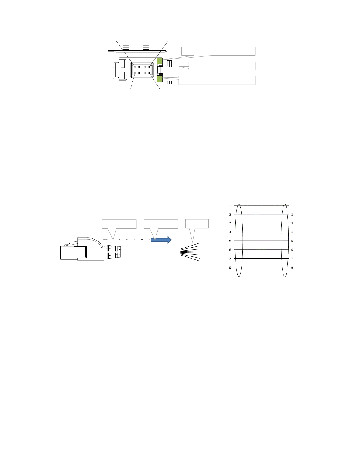
2.1.3 RJ.5 Connector...........................................................................................8
2.1.4 RJ.5 Cable...................................................................................................9
2.1.5 Connection Kits..........................................................................................9
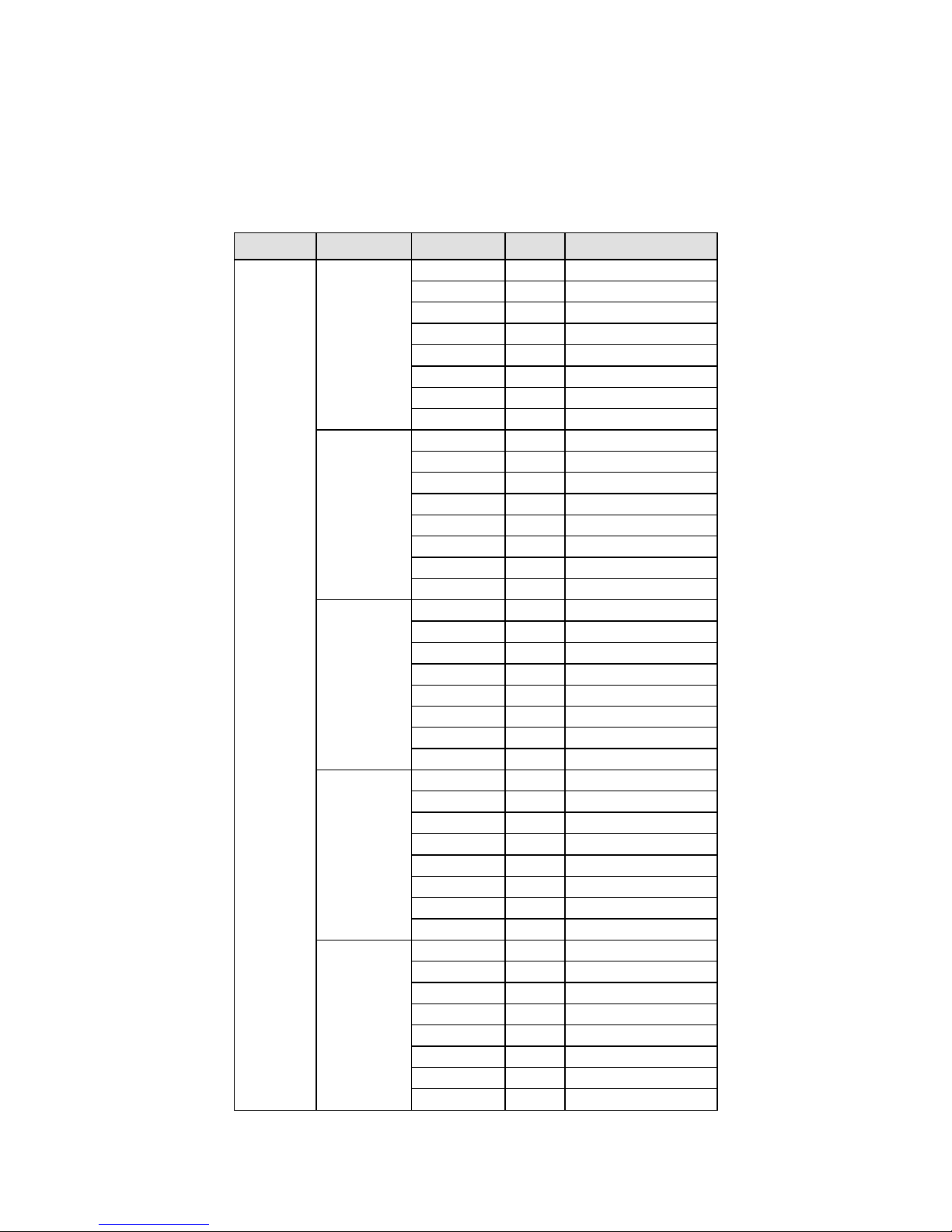
2.1.6 Signals per Serial Port ..............................................................................12
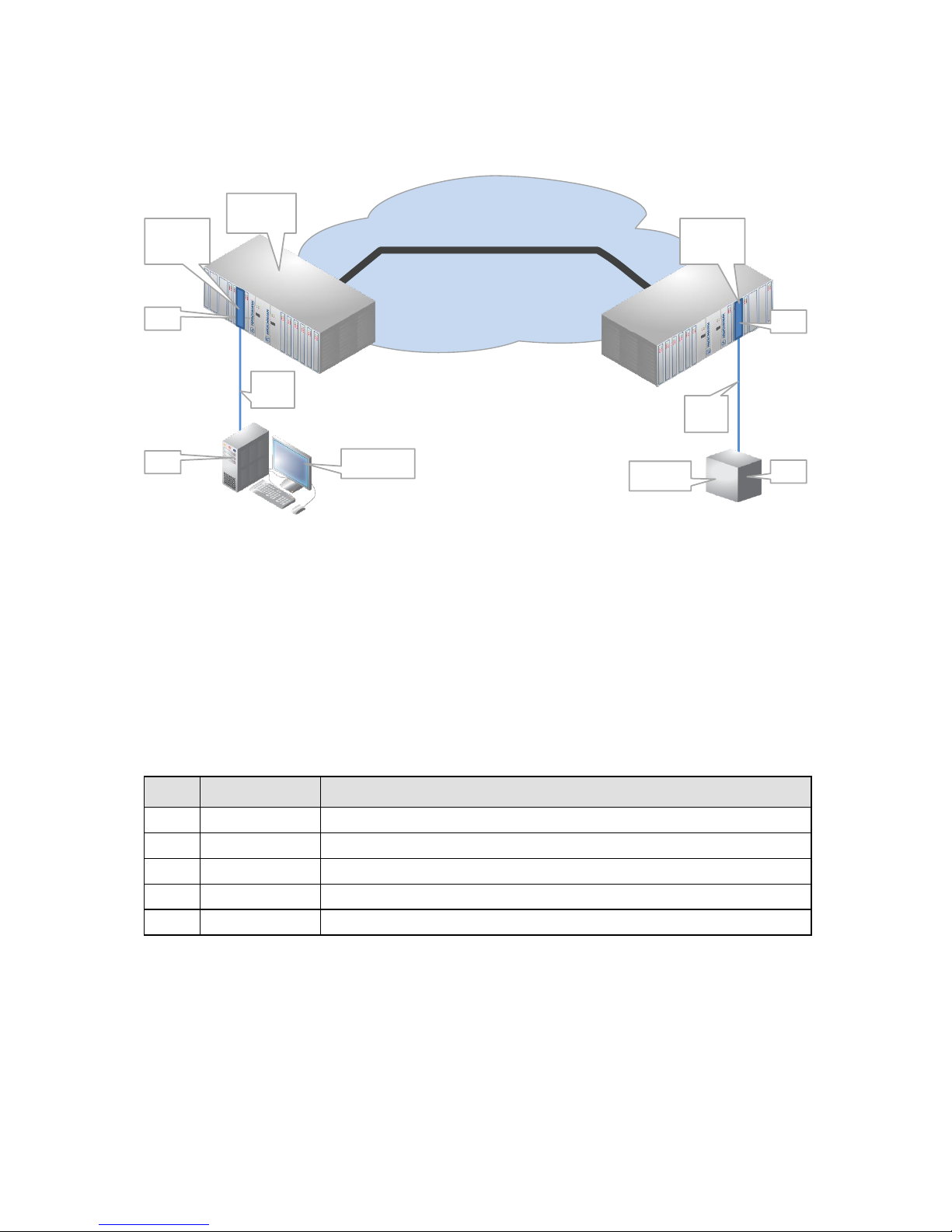
2.2 Functional Operation ........................................................................ 13
2.2.1 General ....................................................................................................13
2.2.2 Service Combination Examples per IFM..................................................13
2.2.3 Port Interface Types ................................................................................15
2.2.4 Serial Port Role DTE/DCE .........................................................................15
2.2.5 Synchronization Parameter .....................................................................15
2.2.6 Pin Layout Parameter ..............................................................................16
2.2.7 Services ....................................................................................................16
2.2.8 CES: CESoPSN (Point-to-Point).................................................................17
2.2.9 CES: Hitless Switching ..............................................................................17
2.2.10 CES: Single Path .......................................................................................18
2.2.11 CES: Delay Comparison in CES Features ..................................................19
2.2.12 Serial Ethernet (Point-to-Multipoint) ......................................................20
2.2.13 Serial Ethernet: Master/Slave..................................................................20
2.2.14 Serial Ethernet: Advanced Mode - Bandwidth Optimization..................20
2.2.15 Serial Ethernet: Multidrop Consistency...................................................21
2.2.16 I/O with the Central Switching Module (=CSM) ......................................21
2.2.17 Synchronization / Clock Distribution / Network Timing..........................21
2.2.18 Test and Loopback Selftests ....................................................................24
2.3 Onboard Interfaces ...........................................................................24
2.3.1 Straps .......................................................................................................24
2.3.2 DIP Switches ............................................................................................24
3. TDM FRAMES/PACKET FOR CES................................................................................ 25
3.1 General............................................................................................. 25
3.2 Bandwidth........................................................................................ 25
3.3 Delay ................................................................................................26
3.3.1 General ....................................................................................................26
3.3.2 Delay Parameters ....................................................................................26
3.3.3 Estimated Delay Calculation and Formulas .............................................27
3.3.4 Estimated Delay Examples.......................................................................27
3.4 Tuning CES = Tuning TDM Frames/Packet.......................................... 27

4 Installation PTN-7-SERIAL
Release 01 02/2018
4. MODULE SPECIFICATIONS ........................................................................................ 28
4.1 General Specifications....................................................................... 28
4.2 Other Specifications..........................................................................28
4.3 Ordering Information........................................................................ 28
5. ABBREVIATIONS ...................................................................................................... 28
List of figures
Figure 1 Functional Overview Matrix ............................................................................................ 5
Figure 2 General 7-SERIAL Example .............................................................................................. 6
Figure 3 Front Panel And Connection Kits..................................................................................... 7
Figure 4 RJ.5 Connector................................................................................................................. 9
Figure 5 RJ.5 Cable/Pin Numbering/Color Coding......................................................................... 9
Figure 6 Example1 ....................................................................................................................... 13
Figure 7 Example2 ....................................................................................................................... 14
Figure 8 Example3 ....................................................................................................................... 14
Figure 9 Example4 ....................................................................................................................... 15
Figure 10 Hitless Switching.......................................................................................................... 18
Figure 11 Single Path Enabled ..................................................................................................... 19
Figure 12 Single Path Disabled .................................................................................................... 19
Figure 13 7-SERIAL Clocking/Synchronization Overview............................................................. 22
Figure 14 7-SERIAL: Side View ..................................................................................................... 24
Figure 15 Hardware Edition......................................................................................................... 25
Figure 16 CESoPSN Bandwidth.................................................................................................... 25
Figure 17 Delays .......................................................................................................................... 26
List of Tables
Table 1 Manual References........................................................................................................... 6
Table 2 LED Indications In Boot Operation ................................................................................... 8
Table 3 LED Indications In Normal Operation ............................................................................... 8
Table 4 RJ.5 Cables to Serial Ports Mapping (Basic Kit)............................................................... 10
Table 5 RJ.5 Cables to Serial Ports Mapping (Extension Kit) ....................................................... 11
Table 6 Signals per Serial Port ..................................................................................................... 12
Table 7 Difference Between Hitless and Protection Switching................................................... 18
Table 8 Delay Comparison in CES (Features)............................................................................... 19
Table 9 Clocking Parameters on Port & Service Level................................................................. 23
Table 10 Estimated Delay Formulas ............................................................................................ 27
Table 11 Estimated Delay (µs) Examples..................................................................................... 27
Table 12 Other Specifications...................................................................................................... 28

Installation PTN-7-SERIAL 5
Release 01 02/2018
1. INTRODUCTION
1.1 General
This document is valid as of Dragon PTN Release 3.0DR.
This document describes the 7-SERIAL interface module (=IFM) which provides 7 logical
serial ports.
Depending on how the IFM is used, the amount of available serial ports varies from 4 to 7
per IFM. The matrix figure below indicates how many and which ports (Pn) can be used to
transport the indicated protocol (RS232...) in the indicated mode (Asynchronous,
Synchronous, Optimised, Full) in the indicated service (CES, Serial Ethernet). More
information on all these modes and services can be found further on.
‘CES’: Circuit Emulation Service;
‘X’: this individual port can transport the indicated service;
‘X combi’: these two ports are required to transport the indicated service;
‘spare’: this individual port cannot transport the indicated service, though it can still be
used to transport another service in the matrix, see §2.2.2 for some examples;
A point-to-multipoint service (e.g. SCADA) requires a Serial Ethernet service;
See the figure below for an overview:
Figure 1 Functional Overview Matrix
P1
RS232 RS422 RS485 X.21 V.35
Async
(Serial
Ethernet)
Async
(CES)
Sync
(CES)
Async
(Serial
Ethernet)
Async
(CES)
Sync
(CES)
Async
(Serial
Ethernet)
Async
(CES)
Optimised
(CES)
Full
(CES)
Optimised
(CES)
Full
(CES)
X X X X X spare X X X spare X spare
X X X X X
X combi
X X X
X combi
X
X combi
X spare spare X spare X spare spare spare
X X X X X
X combi
X X X
X combi
X
X combi
X spare spare X spare X spare spare spare
X X X X X
X combi
X X X
X combi
X
X combi
X spare spare X spare X spare spare spare
P2
P3
P4
P5
P6
P7

6 Installation PTN-7-SERIAL
Release 01 02/2018
This IFM can be used in any IFM slot of any node. An IFM slot overview can be found in Ref.
[3] in Table 1.
Figure 2 General 7-SERIAL Example
1.2 Manual References
Table 1 is an overview of the manuals referred to in this manual. ‘&’ refers to the language
code, ‘*’ refers to the manual issue. All these manuals can be found in the HiProvision (=
Dragon PTN Management System) Help function.
Table 1 Manual References
Ref.
Number
Title
[1]
DRA-DRM821-&-*
Dragon PTN and HiProvision Operation
[2]
DRA-DRM801-&-*
Dragon PTN Installation and Operation
[3]
DRB-DRM802-&-*
Dragon PTN Nodes: PTN2210, PTN2209, PTN2206, PTN1104
[4]
DRB-DRM803-&-*
Dragon PTN Switching Module: PTN-CSM310-A
[5]
DRA-DRM810-&-*
Dragon PTN General Specifications
MPLS-TP Dragon PTN Network
WAN (via SFP on fiber)
Serial
Link Serial
Link
e.g. SCADA
DTE
e.g. RTU DTE
DCE
Dragon PTN
Node
Module
7-SERIAL
DCE
Module
7-SERIAL

Installation PTN-7-SERIAL 7
Release 01 02/2018
2. MODULE DESCRIPTION
2.1 Front Panel And Connection Kits
Figure 3 Front Panel And Connection Kits
2.1.1 Handle
a. Insert the Module into the Node
Take the front panel handles to insert or slide the module into the Dragon PTN node. Push
the module thoroughly into the node’s backplane. Next, tighten the two fastening screws in
the front panel corners.
b. Remove the Module from the Node
Untighten the two fastening screws in the front panel corners. Take the front panel handles
to pull out and finally remove the module from the Dragon PTN node.
2.1.2 LEDs
The meaning of the LEDs depends on the mode of operation (= boot or normal) in which the
7-SERIAL module currently is running. After plugging in the module or rebooting it, the
module turns into the boot operation, see Table 2. After the module has gone through all
the cycles in the table below (=rebooted successfully), the module turns into the normal
operation, see LEDs in Table 3.
Handle
Fastening screw
10 RJ.5
connectors
3 Serial ports
CES: port 1,2
Serial Ethernet: port 1,2,3
8
1
Basic
Kit
Extension
Kit
4 Serial ports
CES: port 4,6
Serial Ethernet : port 4,5,6,7
7 Serial ports
CES: port 1,2,4,6
Serial Ethernet : port 1..7
8
1
8
1
8
1
8
1
8
1
8
1
8
1
8
1
8
1
LEDs
LED
Rx Data
LED
Tx Data

8 Installation PTN-7-SERIAL
Release 01 02/2018
Table 2 LED Indications In Boot Operation
Cycle
PI
PF
FLT
Tx Data[1..10]
Rx Data[1..10]
1
x
---
Slow blinking
---
---
2
x
---
Fast blinking
---
---
3
x
---
---
---
---
4
x
---
x
x red
x red
5
x
---
x
x green
x green
x : LED is lit / --- : LED is not lit; The sub cycle times may vary. The entire boot cycle time [1→5] takes
approximately 2 minutes;
Table 3 LED Indications In Normal Operation
LED
Color
Status
PI (=Power Input)
Not lit, dark
+12V power input to the board not OK
Green
+12V power input to the board OK
PF (=Power Failure)
Not lit, dark
power generation on the board itself is OK
Red
power generation on the board itself is erroneous
FLT (=FauLT)
Not lit, dark
no other fault or error situation, different from PF, is active on the module
Red
a fault or error situation, different from PF, is active on the module
Tx Data
RJ.5 Connector ‘x’
Not lit, dark
- No service programmed
- Service programmed: ‘Tx Data’ is not active on serial port ‘x’
Green
Service programmed: ‘Tx Data’ is active on serial port ‘x’
Red
Service programmed but no data receiving from network, e.g. WAN link
interrupted, destination IFM failure....
Rx Data
RJ.5 Connector ‘x’
Not lit, dark
- No service programmed
- Service programmed: ‘Rx Data’ is not active on serial port ‘x’
Green
Service programmed: ‘Rx Data’ is active on serial port ‘x’
Red
Service programmed but no data receiving from network, e.g. WAN link
interrupted, destination IFM failure....
2.1.3 RJ.5 Connector
This connector has 8 pins and 2 bi-color (green/red) LEDs, see figure below. For the meaning
of the LEDs, see Table 3. The LEDs shown on connector ‘x’ show information of serial port ‘x’
although the pins of connector ‘x’ are not necessarily pins of serial port ‘x’ (see Table 4,
Table 5). Example:
RJ.5 connector 1 LEDs show information of serial port 1;
RJ.5 connector 2 LEDs show information of serial port 2; etc.....
RJ.5 connector 8, 9, 10 LEDs are only lit during the self-test in the boot cycle (see Table 2)
but have no further meaning.

Installation PTN-7-SERIAL 9
Release 01 02/2018
Figure 4 RJ.5 Connector
2.1.4 RJ.5 Cable
Each connection kit has five RJ.5 cables. This cable is very suited for high density cabling
compared to traditional RJ45 cables. The RJ.5 cables in the connection kits are open end,
with the color coding of the wires as indicated in the figure below. WH = white; OG =
Orange; GN = Green; BU = Blue; BN = Brown; When a cable is plugged into the RJ.5
connector on the front panel and must be disconnected, remove the connector by pulling
out the unlock handle.
The cable connector has little holes which allow the LED light from the front panel RJ.5
connector to shine through, after the cable has been plugged in.
Figure 5 RJ.5 Cable/Pin Numbering/Color Coding
2.1.5 Connection Kits
The 7-SERIAL module provides 10 RJ.5 connectors on the front with each connector 8 pins.
As a result, a total of 80 pins are used to provide 7 serial ports that are wired out via 2
connection kits. The table below lists a mapping between the front panel connectors and the
7 serial ports; The signals available on the serial port pins depend on the port interface type,
see §2.2.1.
a. Basic Kit
The Basic kit (order n° 942 256-300) must be used to wire out serial port 1, 2 and 3. This kit
includes 5 open end RJ.5 cables of 3 meter marked from 1 to 5. This kit must be connected
to connector [15] on the front panel;
14
85
LED: Tx Data Serial Port ‘x’
1Connector Number = ‘x’
LED: Rx Data Serial Port ‘x’
Open end
WH/OG
OG
WH/GN
GN
BU
WH/BU
WH/BN
BN
SHIELD SHIELD
Unlock handle Pull to unlock

10 Installation PTN-7-SERIAL
Release 01 02/2018
b. Extension Kit
The Extension kit (order n° 942 256-301) must be used to wire out serial port 4, 5, 6 and 7.
This kit includes 5 open end RJ.5 cables of 3 meter marked from 6 to 10. This kit must be
connected to connector [610] on the front panel;
Table 4 RJ.5 Cables to Serial Ports Mapping (Basic Kit)
Cable Kit
RJ.5 Cable
RJ.5 Pin n°
Color
Serial Port –Pin n°
Basic Kit
1
1
WH/OG
1-1
2
OG
1-2
3
WH/GN
1-3
4
GN
1-4
5
BU
1-5
6
WH/BU
1-6
7
WH/BN
1-7
8
BN
1-8
2
1
WH/OG
1-9
2
OG
1-10
3
WH/GN
GND
4
GN
GND
5
BU
GND
6
WH/BU
GND
7
WH/BN
GND
8
BN
GND
3
1
WH/OG
2-1
2
OG
2-2
3
WH/GN
2-3
4
GN
2-4
5
BU
2-5
6
WH/BU
2-6
7
WH/BN
2-7
8
BN
2-8
4
1
WH/OG
2-9
2
OG
2-10
3
WH/GN
3-1
4
GN
3-2
5
BU
3-3
6
WH/BU
3-4
7
WH/BN
3-5
8
BN
3-6
5
1
WH/OG
GND
2
OG
Frame GND
3
WH/GN
Frame GND
4
GN
Frame GND
5
BU
3-7
6
WH/BU
3-8
7
WH/BN
3-9
8
BN
3-10

Installation PTN-7-SERIAL 11
Release 01 02/2018
Table 5 RJ.5 Cables to Serial Ports Mapping (Extension Kit)
Cable Kit
RJ.5 Cable
RJ.5 Pin n°
Color
Serial Port –Pin n°
Extension Kit
6
1
WH/OG
4-1
2
OG
4-2
3
WH/GN
4-3
4
GN
4-4
5
BU
4-5
6
WH/BU
4-6
7
WH/BN
4-7
8
BN
4-8
7
1
WH/OG
4-9
2
OG
4-10
3
WH/GN
5-1
4
GN
5-2
5
BU
5-3
6
WH/BU
5-4
7
WH/BN
5-5
8
BN
5-6
8
1
WH/OG
6-1
2
OG
6-2
3
WH/GN
6-3
4
GN
6-4
5
BU
6-5
6
WH/BU
6-6
7
WH/BN
6-7
8
BN
6-8
9
1
WH/OG
6-9
2
OG
6-10
3
WH/GN
7-1
4
GN
7-2
5
BU
7-3
6
WH/BU
7-4
7
WH/BN
7-5
8
BN
7-6
10
1
WH/OG
5-7
2
OG
5-8
3
WH/GN
5-9
4
GN
5-10
5
BU
7-7
6
WH/BU
7-8
7
WH/BN
7-9
8
BN
7-10

12 Installation PTN-7-SERIAL
Release 01 02/2018
2.1.6 Signals per Serial Port
An individual serial port (‘X’ in Figure 1) has 11 pins whereas a combined serial port (‘X combi’ in Figure 1) has 22 pins. See table below.
In RS232, RS422, X.21, V.35: Pin 9, 10, 20 and 21 are bidirectional pins. If the signal is available, the pin is output in DTE and input in DCE.
Table 4 and Table 5 shows where all these pins are outputted via the basic and extension kit.
Table 6 Signals per Serial Port
Serial
Port
n°
Pin
n°
In/
Out
RS232
RS422
RS485
X.21
V.35
Asynchronous
Synchronous
Asynchronous
Synchronous
Asynchronous
Optimised
Full
Optimised
Full
DTE
DCE
DTE
DCE
DTE
DCE
DTE
DCE
DTE
DCE
DTE
DCE
DTE
DCE
DTE
DCE
n
1
Out1+
TxD
RxD
TxD
RxD
TxDb
RxDb
TxDb
RxDb
Tri-state
TxDb
RxDb
TxDb
RxDb
TxDb
RxDb
TxDb
RxDb
2
Out1-
RTS
CTS
RTS
CTS
TxDa
RxDa
TxDa
RxDa
Tri-state
TxDa
RxDa
TxDa
RxDa
TxDa
RxDa
TxDa
RxDa
3
In1+
RxD
TxD
RxD
TxD
RxDb
TxDb
RxDb
TxDb
---
RxDb
TxDb
RxDb
TxDb
RxDb
TxDb
RxDb
TxDb
4
In1-
CTS
RTS
CTS
RTS
RxDa
TxDa
RxDa
TxDa
---
RxDa
TxDa
RxDa
TxDa
RxDa
TxDa
RxDa
TxDa
5
Out2+
---
---
TTC
RxC
RTSb
CTSb
TTCb
RxCb
Tri-state
Cb
Ib
Cb
Ib
TTCb
RxCb
TTCb
RxCb
6
Out2-
DTR
DSR
DTR
DSR
RTSa
CTSa
TTCa
RxCa
Tri-state
Ca
Ia
Ca
Ia
TTCa
RxCa
TTCa
RxCa
7
In2+
---
---
RxC
TTC
CTSb
RTSb
RxCb
TTCb
---
Ib
Cb
Ib
Cb
RxCb
TTCb
RxCb
TTCb
8
In2-
DSR
DTR
DSR
DTR
CTSa
RTSa
RxCa
TTCa
---
Ia
Ca
Ia
Ca
RxCa
TTCa
RxCa
TTCa
9
In3/Out3+
---
---
TxC(In)
TXC(Out)
DCDb(In)
DCDb(Out)
TxCb(In)
TXCb(Out)
TRxDb
Sb(In)
Sb(Out)
Sb(In)
Sb(Out)
TxCb(In)
TXCb(Out)
TxCb(In)
TXCb(Out)
10
In3/Out3-
DCD(In)
DCD(Out)
DCD(In)
DCD(Out)
DCDa(In)
DCDa(Out)
TxCa(In)
TXCa(Out)
TRxDa
Sa(In)
Sa(Out)
Sa(In)
Sa(Out)
TxCa(In)
TXCa(Out)
TxCa(In)
TXCa(Out)
11
GND
GND
GND
GND
GND
GND
GND
GND
GND
GND
GND
GND
GND
GND
GND
GND
GND
GND
n+1
(=combi)
1
Out1+
RTSb
CTSb
Xb
Bb
---
---
2
Out1-
RTSa
CTSa
Xa
Ba
RTS
CTS
3
In1+
CTSb
RTSb
Bb
Xb
---
---
4
In1-
CTSa
RTSa
Ba
Xa
CTS
RTS
5
Out2+
DTRb
DSRb
---
---
---
---
6
Out2-
DTRa
DSRa
---
---
DTR
DSR
7
In2+
DSRb
DTRb
---
---
---
---
8
In2-
DSRa
DTRa
---
---
DSR
DTR
9
In3/Out3+
DCDb(In)
DCDb(Out)
---
---
---
---
10
In3/Out3-
DCDa(In)
DCDa(Out)
---
---
DCD(In)
DCD(Out)
11
GND
GND
GND
GND
GND
GND
GND

Installation PTN-7-SERIAL 13
Release 01 02/2018
2.2 Functional Operation
2.2.1 General
Depending on how the IFM is used, the amount of available serial ports varies from 4 to 7
per IFM. See Figure 1 for an overview matrix. The figure indicates how many and which ports
(Pn) can be used to transport the indicated protocol (RS232...) in the indicated mode
(Asynchronous, Synchronous, Optimised, Full) in the indicated service (CES, Serial Ethernet).
Functional overview matrix, see Figure 1;
Service Combination Examples per IFM: see §2.2.2;
Supported interface types or protocols: see §2.2.3;
Port role DTE/DCE: see §2.2.4;
Synchronization parameter (Asynchronous/Synchronous): see §2.2.5;
Pin Layout parameter (Full/Optimised): see §2.2.6;
Services (CES/Serial Ethernet): see §2.2.7;
2.2.2 Service Combination Examples per IFM
The figures below some examples how the transport of different serial services can be -
combined on one 7-SERIAL IFM. All the examples below have all the 7 serial ports in use. A
green highlighted box indicates a used port for the indicated service.
Example1:
Transports 4 services in total;
P1 transports an Asynchronous RS232 protocol via a Serial Ethernet service.
P2+P3 transports a Full V.35 protocol via a CES service;
P4+P5 transports a Full V.35 protocol via a CES service;
P6+P7 transports a Full V.35 protocol via a CES service;
Figure 6 Example1
P1
RS232 RS422 RS485 X.21 V.35
Async
(Serial
Ethernet)
Async
(CES)
Sync
(CES)
Async
(Serial
Ethernet)
Async
(CES)
Sync
(CES)
Async
(Serial
Ethernet)
Async
(CES)
Optimised
(CES)
Full
(CES)
Optimised
(CES)
Full
(CES)
X X X X X spare X X X spare X spare
X X X X X
X combi
X X X
X combi
X
X combi
X spare spare X spare X spare spare spare
X X X X X
X combi
X X X
X combi
X
X combi
X spare spare X spare X spare spare spare
X X X X X
X combi
X X X
X combi
X
X combi
X spare spare X spare X spare spare spare
P2
P3
P4
P5
P6
P7
3*V.35 (Full) + 1*RS232 Async

14 Installation PTN-7-SERIAL
Release 01 02/2018
Figure 7 Example2
Figure 8 Example3
P1
RS232 RS422 RS485 X.21 V.35
Async
(Serial
Ethernet)
Async
(CES)
Sync
(CES)
Async
(Serial
Ethernet)
Async
(CES)
Sync
(CES)
Async
(Serial
Ethernet)
Async
(CES)
Optimised
(CES)
Full
(CES)
Optimised
(CES)
Full
(CES)
X X X X X spare X X X spare X spare
X X X X X
X combi
X X X
X combi
X
X combi
X spare spare X spare X spare spare spare
X X X X X
X combi
X X X
X combi
X
X combi
X spare spare X spare X spare spare spare
X X X X X
X combi
X X X
X combi
X
X combi
X spare spare X spare X spare spare spare
P2
P3
P4
P5
P6
P7
3*RS232 Sync + 4*RS422 Async
P1
RS232 RS422 RS485 X.21 V.35
Async
(Serial
Ethernet)
Async
(CES)
Sync
(CES)
Async
(Serial
Ethernet)
Async
(CES)
Sync
(CES)
Async
(Serial
Ethernet)
Async
(CES)
Optimised
(CES)
Full
(CES)
Optimised
(CES)
Full
(CES)
X X X X X spare X X X spare X spare
X X X X X
X combi
X X X
X combi
X
X combi
X spare spare X spare X spare spare spare
X X X X X
X combi
X X X
X combi
X
X combi
X spare spare X spare X spare spare spare
X X X X X
X combi
X X X
X combi
X
X combi
X spare spare X spare X spare spare spare
P2
P3
P4
P5
P6
P7
2*V.35 (Full) + 1*RS232 Async + 2*RS422 Async

Installation PTN-7-SERIAL 15
Release 01 02/2018
Figure 9 Example4
2.2.3 Port Interface Types
Each serial port can be configured via HiProvision (= Dragon PTN Management System) in
one of the interface types listed below. This setting occurs at service creation. As a result,
both end points or ports will have the same setting after the service creation.
RS232 / RS422 / RS485 / X.21 / V.35;
2.2.4 Serial Port Role DTE/DCE
For the protocols RS232, RS422, X.21, V.35, each serial port can be configured via HiProvision
in the port role DTE or DCE. By default, when a service is configured on a port, its port role is
set automatically to DCE. If it must be changed to DTE, it must be done later on via changing
the port settings in the Network Hardware tab.
DTE (=Data Terminal Equipment): Example: PC, RTU, terminal, printer, etc.
DCE (=Data Communication Equipment): modems etc.
NOTE: Not relevant for RS485;
2.2.5 Synchronization Parameter
Synchronous: both the transmitter and receiver use a clock to exchange data. The clock
is transmitted over the network as well;
Asynchronous: no clock is exchanged between the transmitter and receiver. Only data is
exchanged. Both the transmitter and receiver use start and stop bits to indicate the start
and stop of data;
P1
RS232 RS422 RS485 X.21 V.35
Async
(Serial
Ethernet)
Async
(CES)
Sync
(CES)
Async
(Serial
Ethernet)
Async
(CES)
Sync
(CES)
Async
(Serial
Ethernet)
Async
(CES)
Optimised
(CES)
Full
(CES)
Optimised
(CES)
Full
(CES)
X X X X X spare X X X spare X spare
X X X X X
X combi
X X X
X combi
X
X combi
X spare spare X spare X spare spare spare
X X X X X
X combi
X X X
X combi
X
X combi
X spare spare X spare X spare spare spare
X X X X X
X combi
X X X
X combi
X
X combi
X spare spare X spare X spare spare spare
P2
P3
P4
P5
P6
P7
4*X.21 Optimised + 3*RS232 Async

16 Installation PTN-7-SERIAL
Release 01 02/2018
2.2.6 Pin Layout Parameter
This parameter is only relevant for X.21 and V.35. See Table 6.
Full: indicates that all protocol signals are fully supported and transported. As a result,
this service requires a combi port ‘X combi’;
Optimised: indicates an optimised pin layout of the available protocol signals. It means
that only the essential signals are transported. As a result, this service only requires one
port ‘X’, which leaves some spare ports to transport other protocols;
X.21: One clock and all control signals are transmitted;
V.35: All three clocks are transmitted, but not the control signals;
2.2.7 Services
Serial communication can be configured in HiProvision via creating a CES or Serial Ethernet
Service.
CES (=Circuit Emulation Service): use this service when Point-to-Point is needed. Serial
data will be encapsulated in TDM packets which will be sent over the Dragon PTN
network as Ethernet packets. CES on the 7-SERIAL IFM is not compatible with CES on the
4-E1-L/4-T1-L/16-E1-L/16-T1-L or C37.94 IFM;
Serial Ethernet: use this service when Point-to-Multipoint (e.g. SCADA) is needed. Serial
data will be encapsulated directly into Ethernet packets and sent over the Dragon PTN
network. All 7 ports can transport such a service. Master(s)/slave(s) must be configured
in this service.
Following parameters are needed per service:
CES: Service Type: Circuit Emulation;
Protocol: Serial;
Usage is always CESoPSN;
optional: Hitless Switching;
optional: Single Path;
Synchronization: Synchronous/Asynchronous;
Interface Type:
Asynchronous: RS232/RS422/RS485;
Synchronous: RS232/RS422/X.21/V.35;
Bitrate;
Pin Layout: Full/Optimised
Serial Ethernet: Service Type: Serial Ethernet;
(Always Asynchronous)
Interface Type: RS232/RS422/RS485;
Bitrate;
Stop Bits;
Data Bits;
Parity;
Master(s)/Slave(s) selection;

Installation PTN-7-SERIAL 17
Release 01 02/2018
2.2.8 CES: CESoPSN (Point-to-Point)
CESoPSN (=Circuit Emulation Service over Packet Switched Network) is a point-to-point
service between two serial ports. One such service can be configured per port. This service
converts the incoming serial data into an amount of timeslots, to transport it over the MPLS-
TP Dragon PTN network. The amount of timeslots over the network just depends on the
selected bit rate.
The destination module will receive the transported timeslots from the Dragon PTN network
and regenerate the serial data from it. As a result, the destination sends out the regenerated
serial data on its serial port.
Each end-point or port must be located in a different node.
2.2.9 CES: Hitless Switching
Hitless Switching is a feature within CESoPSN that provides a safe redundant connection
where no data or synchronization is lost when switching from the active to the backup path
or vice versa, e.g. because of cable break. The total delay over the network remains nearly
constant during switch-over. Redundancy via Hitless Switching is obtained via completing the
list below:
creating two independent point-to-point tunnels without protection;
setting the Hitless Switching on at service creation time in HiProvision.
NOTE: See Ref.[1] for the creation of tunnels and services;
On the source side, with Hitless Switching enabled, the IFM duplicates each packet on a
second tunnel (e.g. Tunnel y, see figure below). Each packet also contains a 16 bit sequence
number. Different tunnels mean different paths through the network, with each path its
own delay. Different delays result in a slow and a fast path.
On the destination side, with Hitless Switching enabled, the IFM buffers the fastest path and
forwards packets from the slowest path on the serial link. Packets will be processed
according a packet sequence number.
Hitless Switching is a redundant mechanism but differs from Protection Switching, see the
table below for an overview. So if redundancy is needed in the service, either choose Hitless
Switching or Protection Switching, mixing up both mechanisms is not allowed. Depending on
the choice, settings must be done at tunnel creation time and/or service creation time.
When Hitless Switching has been enabled, the CES can only start up with two links up,
coming out of a two-links-down situation (except when Single Path has been enabled, see
§2.2.10).
See §2.2.11 for a delay comparison within CES depending on the enabled sub features, see
also further on.

18 Installation PTN-7-SERIAL
Release 01 02/2018
Table 7 Difference Between Hitless and Protection Switching
Protection Switching
Hitless Switching
required tunnel type
1 point-to-point tunnel
2 point-to-point tunnels
tunnel protection type
1:1;
none; the redundancy is created via two
independent point-to-point tunnels.
service parameter
Hitless Switching = disabled
Hitless Switching = enabled
at switch-over
possible data loss
no data or synchronization loss
total delay
less than hitless switching
more than protection switching
Figure 10 Hitless Switching
2.2.10 CES: Single Path
The Single Path feature is a sub feature of Hitless Switching (see §2.2.9). It influences the
start-up behavior of the Hitless Switching mechanism:
enabled: The CES can already start up with only one link up, coming out of a two-links-
down situation; this setting results in bigger delays because of bigger buffers.
if the fastest path came up first:
the CES starts up according to the fastest path;
possible CES interrupt or minor packet loss when the slowest path comes up
later on;
if the slowest path came up first:
the CES starts up according to the slowest path;
no CES interrupt or packet loss when the fastest path comes up later on;
See §2.2.11 for a delay comparison within CES depending on the enabled sub features, see
also further on.
Serial Data
data
Serial Data
data
Serial WAN:
duplicates and transmits
data twice
WAN Serial:
data buffering = constant delay;
no packet loss at switch-over
MPLS-TP Dragon PTN
Tunnel x has more nodes
= slow path
Tunnel y has less nodes
= fast path

Installation PTN-7-SERIAL 19
Release 01 02/2018
Figure 11 Single Path Enabled
Figure 12 Single Path Disabled
2.2.11 CES: Delay Comparison in CES Features
Table 8 Delay Comparison in CES (Features)
CES
Hitless Switching
Single Path
Resulting Delay
X
---
---
lowest
X
X
---
medium
X
X
X
highest
X = enabled; --- = disabled
data data
Single Path ENABLED:
ONE link required
no links up:
no CES
already with one link up
CES starts
Serial Data Serial Data
MPLS-TP Dragon PTN
MPLS-TP Dragon PTN
data
Serial Data
data
Single Path DISABLED:
BOTH links required
only with both links up
CES starts
no links up:
no CES
Serial Data
MPLS-TP Dragon PTN
MPLS-TP Dragon PTN

20 Installation PTN-7-SERIAL
Release 01 02/2018
2.2.12 Serial Ethernet (Point-to-Multipoint)
Serial Ethernet is a point-to-multipont service between two or more serial ports, e.g. for
SCADA systems. One such service can be configured per port. This service converts the
incoming serial data directly into Ethernet packets, to transport it over the MPLS-TP Dragon
PTN network.
The destination module will receive the Ethernet packets from the Dragon PTN network and
regenerate the serial data from it. As a result, the destination sends out the regenerated
serial data on its serial port.
At least two nodes are required and each node can have multiple end-points of that service.
2.2.13 Serial Ethernet: Master/Slave
A Serial Ethernet Service is typically used for a point-to-multipoint service, e.g. SCADA
systems. In this service, at least one master (maximum two masters) and one or more slaves
(maximum 156 slaves) must be selected.
When two masters are selected, one of them will be the active one and the other one will be
the backup master. Which one is the active/backup master will be decided by the serial
protocol itself.
The (active) master will initiate commands or requests to their slaves. The backup master
and all the slaves will see this request. Only the addressed slave will process the request and
send a response back to the (active) master. The backup master and all the other slaves will
see the slave response.
Only the (active) master will process the slave response. The backup master (if any) will be
synchronized with the active master and will take over when the active master gets out of
service.
2.2.14 Serial Ethernet: Advanced Mode - Bandwidth Optimization
At service creation, fine-tuning the bandwidth and delay through the network is done via the
Advanced Mode parameter. It groups payload data more efficiently in the transmit process
resulting in less overhead. Note that less bandwidth results in more delay and vice versa.
Serial data is collected at the front ports and buffered until one of the events below is
triggered. After the trigger, the payload data is packetized and sent over the Dragon PTN
network.
Amount of payload bytes received at the front (Fixed Block size);
Periodic transmit timer expires (Fixed Transmit Timer);
Detection of a line termination character (Delimiter: Line Termination Character);
Timeout occurs after the last received byte (Delimiter Timeout);
See the HiProvision manual for more info: Ref.[1] in Table 1;
Table of contents
Other Hirschmann Control Unit manuals

Hirschmann
Hirschmann Dragon PTN Series User manual

Hirschmann
Hirschmann Dragon PTN Series User manual

Hirschmann
Hirschmann PTN-2-C37.94 User manual

Hirschmann
Hirschmann Rotarus PK 10-16 User manual

Hirschmann
Hirschmann PRS 80 User manual

Hirschmann
Hirschmann Dragon PTN Series User manual

Hirschmann
Hirschmann PTN-4-2/4WEM User manual

Hirschmann
Hirschmann Dragon PTN Series User manual

Hirschmann
Hirschmann Dragon PTN Series User manual

Hirschmann
Hirschmann PTN-4-DSL-LW User manual