Hirschmann RT1-TP/FL Manual

Beschreibung und Betriebsanleitung
ETHERNET Rail Transceiver
Medienwandler 10BASE-T/10BASE-FL
RT1-TP/FL
Der Medienwandler (Rail Transceiver)
RT1-TP/FL ermöglicht den Medienüber-
gang von 10BASE-T (Twisted Pair-Verka-
belung ) nach 10BASE-FL (Lichtwellenlei-
ter).
Das Modul ist konform zu den Spezifika-
tionen der Norm IEEE 802.3 bzw. ISO/IEC
8802-3.
Der Medienwandler verfügt über eine
Twisted Pair (TP)-Schnittstelle (RJ45-
Buchse) und eine optische Schnittstelle
(BFOC). Über TP kann ein Endgerät oder
weitere TP-Netzkomponenten ange-
schlossen werden; über LWL ist der
Anschluß eines weiteren Endgerätes
oder einer optischen Netzkomponente
(RH1-TP/FL, ECFL2, Mini-OTDE, etc.)
möglich.
Kontroll-LEDs für
– Power,
– Datenempfang
– Link-Status
Meldung der Linkstati abschaltbar
Einsatz in industrieller Umgebung
Der Medienwandler wird auf die Hut-
schiene aufgesteckt
Geringe Stromaufnahme
Kompakte Bauform
Eine ausführliche Beschreibung des Auf-
baus eines lokalen Netzes und Hinweise
zur Netzplanung und Installation finden
Sie im „Handbuch Ethernet“ (Best.Nr.
943 320-001).
Bestell-Nr.
943 633-001
Railtransceiver
RT1-TP/FL
DIL-Switch-Settings:
Port 1 … Port 2
LA1 … LA2 Link Alarm
0 Disabled
1 Enabled
Made in Germany
P1
DA/
STAT 1
P2
DA/
STAT 2
Port 1
RT1-TP/FL

2
Sicherheitshinweise
vWarnung!
Die Geräte RT1-TP/FL sind für
den Betrieb mit Sicherheits-
kleinspannung ausgelegt. Ent-
sprechend dürfen an die Versor-
gungsspannungsanschlüsse
sowie an den Meldekontakt nur
Sicherheitskleinspannungen
(SELV) nach IEC950/ EN60950/
VDE0805 angeschlossen werden.
Wir haben den Inhalt der Druckschrift auf
Übereinstimmung mit der beschriebe-
nen Hard- und Software geprüft. Den-
noch können Abweichungen nicht aus-
geschlossen werden, so daß wir für die
vollständige Übereinstimmung keine
Gewähr übernehmen. Die Angaben in
der Druckschrift werden jedoch regel-
mäßig überprüft. Notwendige Korrektu-
ren sind in den nachfolgenden Auflagen
enthalten. Für Verbesserungsvorschläge
sind wir dankbar.
Technische Änderungen vorbehalten.
Weitergabe sowie Vervielfältigung dieser
Unterlage, Verwertung und Mitteilung
ihres Inhalts ist nicht gestattet, soweit
nicht ausdrücklich zugestanden. Zuwi-
derhandlungen verpflichten zu Scha-
densersatz. Alle Rechte vorbehalten, ins-
besondere für den Fall der Patentertei-
lung oder GM-Eintragung.
Copyright
© Richard Hirschmann GmbH & Co. 1998
All Rights Reserved
Hinweis
Wir weisen darauf hin, daß der Inhalt
dieser Betriebsanleitung nicht Teil einer
früheren oder bestehenden Vereinba-
rung, Zusage oder eines Rechtsverhält-
nisses ist oder diese abändern soll.
Sämtliche Verpflich-tungen von Hirsch-
mann ergeben sich aus dem jeweiligen
Kaufvertrag, der auch die vollständige
und allein gültige Gewährleistungsregel
enthält. Diese vertraglichen Gewährlei-
stungsbestimmungen werden durch die
Ausführungen dieser Betriebsanleitung
weder erweitert noch beschränkt.
Wir weisen außerdem darauf hin, daß
aus Gründen der Übersichtlichkeit in die-
ser Betriebsanleitung nicht jede nur
erdenkliche Problemstellung im Zusam-
menhang mit dem Einsatz dieses Gerä-
tes beschrieben werden kann. Sollten
Sie weitere Informationen benötigen
oder sollten besondere Probleme auftre-
ten, die in der Betriebsanleitung nicht
ausführlich genug behandelt werden,
können Sie die erforderliche Auskunft
über den Hirschmann-Vertragspartner in
Ihrer Nähe oder direkt bei Hirschmann
(Adresse siehe im Abschnitt „Hinweis
zur CE-Kennzeichnung“) anfordern.
Allgemeines
Dieses Gerät wird mit Elektrizität betrie-
ben. Beachten Sie genauestens die in
der Betriebsanleitung vorgeschriebenen
Sicherheitsanforderungen an die anzule-
genden Spannungen!
vWarnung!
Bei Nichtbeachten der Warnhin-
weise können deshalb schwere
Körperverletzungen und/oder
Sachschäden auftreten.
Nur entsprechend qualifiziertes
Personal sollte an diesem Gerät
oder in dessen Nähe arbeiten.
Dieses Personal muß gründlich
mit allen Warnungen und
Instandhaltungsmaßnahmen
gemäß dieser Betriebsanleitung
vertraut sein.
Der einwandfreie und sichere
Betrieb dieses Gerätes setzt sach-
gemäßen Transport, fachgerech-
te Lagerung und Montage sowie
sorgfältige Bedienung und
Instandhaltung voraus.
Anforderung an die Qualifi-
kation des Personals
Qualifiziertes Personal im Sinne dieser
Betriebsanleitung bzw. der Warnhinwei-
se sind Personen, die mit Aufstellung,
Montage, Inbetriebsetzung und Betrieb
dieses Produktes vertraut sind und die
über die ihrer Tätigkeit entsprechenden
Qualifikationen verfügen, wie z.B.:
– Ausbildung oder Unterweisung bzw.
Berechtigung, Stromkreise und Geräte
bzw. Systeme gemäß den aktuellen
Standards der Sicherheitstechnik ein-
und auszuschalten, zu erden und zu
kennzeichnen;
– Ausbildung oder Unterweisung gemäß
den aktuellen Standards der Sicher-
heitstechnik in Pflege und Gebrauch
angemessener Sicherheitsausrüstun-
gen;
– Schulung in erster Hilfe.

3
1. Funktionsbeschreibung
1.1 ALLGEMEINE FUNKTIONEN
Signalregenerierung
Der RT1-TP/FL bereitet Signalform und
Amplitude der empfangenen Daten auf.
1.2 SPEZIFISCHE FUNKTIONEN
DER TP-SCHNITTSTELLE
Leitungsüberwachung (Link Control)
Mit Idle-Signalen in Paketpausen gemäß
der Norm IEEE 802.3 10BASE-T über-
wacht der RT1-TP/FL die angeschlosse-
nen TP-Leitungssegmente auf Kurz-
schluß oder Unterbrechung. Der RT1-
TP/FL sendet keine Daten in ein TP-Seg-
ment, von dem er kein Idle-Signal emp-
fängt.
Hinweis: Eine nicht belegte Schnittstelle
wird als Leitungsunterbrechung bewer-
tet. Ebenso wird die TP-Strecke zu einem
ausgeschalteten Endgerät als Leitungs-
unterbrechung bewertet, da der stromlo-
se Transceiver keine Idle-Signale senden
kann.
Polaritätsumkehrung
(Auto Polarity Exchange)
Ist das Empfangsleitungspaar falsch
angeschlossen (RD+ und RD- ver-
tauscht), dann erfolgt automatisch die
Umkehrung der Polarität.
1.3 SPEZIFISCHE FUNKTIONEN
DER LWL-SCHNITTSTELLE
LWL-Überwachung
Mit Idle-Signalen in Paketpausen gemäß
der Norm IEEE 802.3 10BASE-FL über-
wacht der RT1-TP/FL die angeschlosse-
nen LWL-Leitungen auf Unterbrechung.
Der RT1-TP/FL sendet keine Daten in eine
LWL-Leitung, von der er kein Idle-Signal
empfängt.
Low Light Detection: Wenn die optische
Eingangsleistung unter die Low Light-
Schwelle absinkt, werden Sende- und
Empfangspfad des LWL-Ports für Daten
gesperrt und das Idle-Signal wird gesen-
det.
1.4 ANZEIGENELEMENTE
Gerätestatus
Die 4 oben angeordneten LEDs geben
Auskunft über Zustände, die Auswirkung
auf die Funktion des gesamten RT1-
TP/FL haben.
P1 – Power 1 (Grüne LED)
– leuchtet: Versorgungsspannung 1 liegt
an
– leuchtet nicht: – Versorgungsspannung
1 liegt nicht an,
– Hardwarefehler im
RT1-TP/FL
P2 – Power 2 (Grüne LED)
– leuchtet: Versorgungsspannung 2 liegt
an
– leuchtet nicht: – Versorgungsspannung
2 liegt nicht an,
– Hardwarefehler im
RT1-TP/FL
Portstatus
Diese LED-Gruppe zeigt portbezogene
Informationen an.
DA STAT 1 – Daten und Linkstatus
TP-Port (Port 1) (grün/gelbe LED)
– leuchtet gelb: RT1-TP/FL empfängt an
der TP-Schnittstelle
Daten
Je nach Netzlast kann das Leuchten der
LED zwischen kurzzeitigem Aufleuchten
bis zu Dauerlicht variieren.
– leuchtet grün: RT1-TP/FL empfängt
Idle-Signale vom TP-
Segment,
– das angeschlossene
TP-Segment arbeitet
ordnungsgemäß
– leuchtet nicht: RT1-TP/FL empfängt
keine Idle-Signale vom
TP-Segment,
– der zugeordnete TP-
Port ist nicht ange-
schlossen,
– das angeschlossene
Gerät ist ausgeschal-
tet,
– die TP-Leitung ist
unterbrochen oder
kurzgeschlossen
– Hardwarefehler im
RT1-TP/FL
DA STAT 2 – Daten und Linkstatus
FL-Port (Port 2) (grün/gelbe LED)
– leuchtet gelb: RT1-TP/FL empfängt an
der LWL-Schnittstelle
Daten
Je nach Netzlast kann das Leuchten der
LED zwischen kurzzeitigem Aufleuchten
bis zu Dauerlicht variieren.
– leuchtet grün: RT1-TP/FL empfängt
Idle-Signale vom LWL-
Segment,
– das angeschlossene
LWL-Segment arbeitet
ordnungsgemäß.
– leuchtet nicht: RT1-TP/FL empfängt
keine Idle-Signale vom
LWL-Segment,
– der zugeordnete LWL-
Port ist nicht ange-
schlossen,
– das angeschlossene
Gerät ist ausgeschal-
tet,
– Low Light Detection
– die LWL-Empfangsfa-
ser ist unterbrochen
– RT1-TP/FL empfängt
auf der Schnittstelle
keine Daten,
– Hardwarefehler im
RT1-TP/FL
Datenübertragung
– Wenn der RT1-TP/FL am TP-Port nichts
empfängt, wird am LWL-Port nichts
gesendet, auch keine Idle-Signale.
– Wenn der RT1-TP/FL am LWL-Port
nichts empfängt, wird am TP-Port
nichts gesendet, auch keine Idle-
Signale.
Der RT1-TP/FL unterstützt Halbduplex
(HDX)- und Vollduplex (FDX)-Verbindun-
gen. Eine Änderung der Konfiguration ist
nicht notwendig.
1.5 BEDIENELEMENTE
6poliger DIP-Schalter
Mit dem 6poligen DIP-Schalter auf der
Gehäuseoberseite des RT1-TP/FL
– kann die Meldung der Linkstati über
den Meldekontakt portweise unter-
drückt werden. Mit dem Schalter LA1
wird die Meldung des Linkstatus des
TP-Ports (Port 1), mit Schalter LA2 die
Meldung des Linkstatus des FL-Ports
(Port 2) unterdrückt. Auslieferungszu-
stand: Schalterstellung 1 (ON), d.h.
Meldung nicht unterdrückt, der Melde-
kontakt leitet den fehlerhaften Linksta-
tus weiter.
Abb. 1: 6poliger DIP-Schalter
LA1
Off On
LA2 Port 1 (TP)
nicht belegt
nicht belegt
nicht belegt
Port 2 (FL)
nicht belegt
über den Meldekontakt
Meldung des Linkstatus
unterdrücken
01
n.c. Pin 8
n.c. Pin 7
TD- Pin 6
n.c. Pin 5
n.c. Pin 4
Pin 3TD+ Pin 2RD- Pin 1RD+
Abb. 2: Pinbelegung TP-Schnittstelle
1.6 SCHNITTSTELLEN
TP-Anschluß
Eine 8polige RJ45-Buchse erlaubt den
Anschluß eines unabhängigen TP-Seg-
mentes. Das Gehäuse der Buchse ist gal-
vanisch mit der Frontblende und
dadurch mit dem Gehäuse des RT1-
TP/FL verbunden.
– Pinbelegung der RJ45-Buchse:
– TD+: Pin 3, TD-: Pin 6
– RD+: Pin 1, RD-: Pin 2
– Restliche Pins: nicht belegt.

4
LWL-Anschluß
Ein optischer Port nach 10BASE-FL
(BFOC/2,5 (ST)-Buchse) ermöglichet den
Anschluß von Endgeräten oder opti-
schen Netzkomponenten.
5poliger Klemmblock
Der Anschluß der Versorgungsspannung
und des Meldekontaktes erfolgt über
einen 5poligen Klemmblock mit
Schraubverriegelung.
vWarnung!
Die Geräte RT1-TP/FL sind für
den Betrieb mit Sicherheits-
kleinspannung ausgelegt. Ent-
sprechend dürfen an die Versor-
gungsspannungsanschlüsse
sowie an den Meldekontakt nur
Sicherheitskleinspannungen
(SELV) nach IEC950/ EN60950/
VDE0805 angeschlossen werden.
Abb. 3: Pinbelegung 5poliger
Klemmblock
+24V
+24 V *
Fault
L1+
L2+
M
F1
F2
– Spannungsversorgung: Die Versor-
gungsspannung ist redundant ansch-
ließbar. Beide Eingänge sind entkop-
pelt. Es besteht keine Lastverteilung.
Bei redundanter Einspeisung versorgt
das Netzgerät mit der höheren Aus-
gangsspannung das RT1-TP/FL alleine.
Die Versorgungsspannung ist galva-
nisch vom Gehäuse getrennt (>3MΩ).
– Meldekontakt: Der Betriebszustand
des RT1-TP/FL wird bzgl. Linkstatus
und Spannungsversorgung überwacht.
Über einen potentialfreien Meldekon-
takt (Relaiskontakt, Ruhestromschal-
tung) wird durch Kontaktunterbre-
chung gemeldet:
– der Ausfall mindestens einer der zwei
Versorgungsspannungen.
– eine dauerhafte Störung im Medien-
wandler (interne 5 VDC-Spannung,
Versorgungsspannung 1 oder 2 nicht
im zulässigen Bereich).
– der fehlerhafte Linkstatus des TP-
Ports (Port 1), während Schalter LA1
auf „ON“ steht.
– der fehlerhafte Linkstatus des LWL-
Ports (Port 2), während Schalter LA2
auf „ON“ steht.
Die Meldung des Linkstatus kann pro
Port über die DIP-Schalter LA1 und
LA2 maskiert werden.
2. Konfiguration
2.1 ANBINDUNG AN BESTEHENDE
INDUSTRIE-NETZE
Im Industrial Ethernet Bereich können
Endgeräte, Speicherprogrammierbare
Steuerungen (SPS) Automaten etc. über
störungsunempfindliche Lichtwellenlei-
ter angeschlossen werden.
Über den RT1-TP/FL können Geräte an
bestehende Ethernet-Netze mit Konzen-
tratoren aus der ASGE-, MC- und AMC-
Familie oder Railhubs RH1… angebun-
den werden.
Hinweise zur Berechnung der maximalen
Netzausdehnung finden Sie im Hand-
buch Ethernet im Kapitel 8 (Bestellnum-
mer siehe „Technische Daten“). Zwi-
schen Endgeräten bzw. Repeatern kön-
nen Sie maximal zwei RT1-TP/FL kaska-
dieren.
Twisted-Pair-
Leitung
DTE bzw.
Repeater
Trans-
ceiver
LWL-Leitung
RT1-
TP/FL
RT1-
TP/FL
Abb. 4: Konfigurationsmöglichkeit RT1-TP/FL
Der Meldekontakt ist geschlossen,
– wenn die Versorgungsspannungen in
Ordnung sind.
– wenn Schalter LA1 auf „ON“ steht
und der Linkstatus von Port 1 in Ord-
nung ist (oder wenn Schalter LA1 auf
„OFF“ steht).
– wenn Schalter LA2 auf „ON“ steht
und der Linkstatus von Port 2 in Ord-
nung ist (oder wenn Schalter LA2 auf
„OFF“ steht).
Hinweis: Bei nicht redundanter
Zuführung der Versorgungsspannung
meldet der RT1-TP/FL den Ausfall einer
Versorgungsspannung. Sie können diese
Meldung verhindern, indem Sie die Ver-
sorgungsspannung über beide Eingänge
zuführen.

5
3. Montage, Inbetriebnahme
und Demontage
3.1 AUSPACKEN, PRÜFEN
– Überprüfen Sie, ob das Paket komplett
ausgeliefert wurde (siehe
Lieferumfang).
– Überprüfen Sie die Einzelteile auf
Transportschäden.
vWarnung!
Nehmen Sie nur unbeschädigte
Teile in Betrieb!
3.2 MONTAGE
Das Gerät wird in betriebsbereitem
Zustand ausgeliefert. Für die Montage ist
folgender Ablauf zweckmäßig:
– Überprüfen Sie, ob die Schaltervorein-
stellung Ihren Anforderungen ent-
spricht.
– Ziehen Sie den Klemmblock vom RT1-
TP/FL ab und verdrahten Sie die Ver-
sorgungsspannungs- und Meldeleitun-
gen.
– Montieren Sie den RT1-TP/FL auf einer
35 mm Hutschiene nach DIN EN 50 022.
– Hängen Sie die oberen Rasthaken des
RT1-TP/FL in die Hutschiene ein, fahren
Sie mit einem Schraubendreher waa-
gerecht unterhalb des Gehäuses in den
Verriegelungsschieber und ziehen die-
sen nach unten (vgl. Abb. 7, Demonta-
ge) und drücken Sie die Unterseite des
Moduls auf die Hutschiene, bis sie einra-
stet (Abb. 6).
– Montieren Sie die Signalleitungen.
Hinweise:
– Die Erdung des Gehäuses des RT1-
TP/FL erfolgt über die Hutschiene. Ein
separater Erdungsanschluß ist nicht
vorhanden.
– Die Schrauben in den seitlichen Gehäu-
sehalbschalen dürfen auf keinen Fall
gelöst werden.
– Die Schirmungsmasse der anschließ-
baren Twisted Pair-Leitungen ist elek-
trisch leitend mit dem Gehäuse verbun-
den.
Abb. 6: Montage des RT1-TP/FL
Twisted-Pair-
Leitung
DTE
Trans-
ceiver
RH1-
TP/FL
RH1-
TP/FL
RH1-
TP/FL
RT1-
TP/FL
RT1-
TP/FL
Automat
SPS
LWL-Leitung
Automat
LWL-Leitung max. 2600 m (50/125)
LWL-Kabel m ax3100 m (62,5/125) Twisted Pair-
Leitung
Twisted Pair-
Leitung LWL-Leitung
LWL-Leitung
Abb. 5: Applikation mit RT1-TP/FL
3.3 INBETRIEBNAHME
Mit dem Anschluß der Versorgungsspan-
nung über den 5poligen Klemmblock
nehmen Sie den RT1-TP/FL in Betrieb.
Verriegeln Sie den Klemmblock mit der
seitlichen Verriegelungsschraube.
LWL-Verbindung
Am Medienwandler RT1-TP/FL stehen
zwei BFOC-Buchsen als Port für ein LWL-
Segment bereit. Ein Anschluß wird zum
Senden und ein Anschluß zum Empfan-
gen von Daten über LWL genutzt.
Das anschließbare LWL-Segment darf
maximal
– 2600 m bei Fasertyp 50/125
– 3100 m bei Fasertyp 62,5/125
lang sein.
Streckendämpfung
Laut IEEE 802.3 10BASE-T darf die
Streckendämpfung eines einfachen
Kabelsegments nicht mehr als 11,5 dB
bei Frequenzen zwischen 5 und 10 MHz
betragen. Dieser Wert beinhaltet
– die Dämpfung des Twisted-Pair-Kabels,
– Steckerdämpfung und
– Reflektionsverluste bedingt durch Fehl-
anpassung der verschiedenen Kompo-
nenten des einfachen Kabelsegmentes,
z. B. Patchfelder, in denen Twisted-Pair-
Kabel miteinander verbunden werden,
die im Rahmen der Toleranz unterschied-
liche Wellenwiderstände an der Koppel-
stelle besitzen.

6
P1
DA/
STAT 1
P2
DA/
STAT 2
Port 1
RT1-TP/FL
Verriegelung
Abb. 7: Demontage des RT1-TP/FL
4. Weitere Unterstützung
Bei technischen Fragen wenden Sie sich
bitte an den Hirschmann-Vertragspartner
in Ihrer Nähe oder direkt an Hirschmann.
Die Adressen unserer Vertragspartner
finden Sie
– im Internet
(http://www.hirschmann.de).
Darüber hinaus steht Ihnen unsere Hotli-
ne zur Verfügung:
Tel. +49(7127) 14-1538 (Fax -1542)
5. Technische Daten
Allgemeine Daten
Betriebsspannung DC 18 bis 32 V Sicherheitskleinspannung (SELV)
(redundante Eingänge entkoppelt)
Stromaufnahme typ. 80 mA bei 24 VDC
max. 100 mA bei 24 VDC
Überstromschutz am Eingang nicht wechselbare Schmelzsicherung
Abmessungen B x H x T 40 mm x 134 mm x 80 mm
Masse 520 g
Umgebungstemperatur 0 ºC bis + 60 ºC
Lagerungstemperatur - 40 ºC bis + 80 ºC
Luftfeuchtigkeit 10% bis 90% (nicht kondensierend)
Schutzklasse IP 30
Funkstörgrad EN 55022 Class B
Störfestigkeit EN 50082-2
Netzausdehnung
Übergang TP-Port ↔LWL-Port
Laufzeitäquivalent 50 m
Variability Value 1 BT
LWL-Port
Optische Ausgangsleistung
Gradientenfaser 50/125 µm (average) min. -22,0 dBm max. -16,2 dBm
Gradientenfaser 62,5/125 µm (average) min. -19,0 dBm max. -12,4 dBm
Optische Eingangsleistung min. -33,0 dBm
TP-Leitungslänge (TP-Port ↔TP-Port)
Länge eines Twisted Pair-Segmentes max. 100 m
3.4 DEMONTAGE
Um den RT1-TP/FL von der Hutschiene
zu demontieren, fahren Sie mit einem
Schraubendreher waagerecht unterhalb
des Gehäuses in den Verriegelungsschie-
ber, ziehen diesen – ohne den Schrau-
bendreher zu kippen – nach unten und
klappen den RT1-TP/FL nach oben
(Abb. 7).

7
Hinweis zur
CE-Kennzeichnung
Die Twisted Pair Hutschienen-
hubs stimmen mit den Vor-
schriften der folgenden Europäi-
schen Richtlinie überein:
89/336/EWG
Richtlinie des Rates zur Anglei-
chung der Rechtsvorschriften
der Mitgliedstaaten über die
elektromagnetische Verträglich-
keit
(geändert durch RL 91/263/EWG,
92/31/EWG und 93/68/EWG).
Einsatzbereich Anforderungen an
Störaussendung Störfestigkeit
Wohnbereich EN 50081-1: 1992 EN 50082-1: 1992
Industriebereich EN 50081-2: 1993 EN 50082-2: 1995
Das Produkt ist einsetzbar im Wohnbe-
reich (Wohnbereich, Geschäfts- und
Gewerbebereiche sowie Kleinbetriebe)
sowie im Industriebereich.
Voraussetzung für die Einhaltung der
EMV-Grenzwerte ist die strikte Einhal-
tung der in dieser Beschreibung und
Betriebsanleitung angegebenen Aufbau-
richtlinien.
Die EU-Konformitätserklärung wird
gemäß der obengenannten EU-Richtlini-
en für die zuständigen Behörden zur Ver-
fügung gehalten bei:
Richard Hirschmann GmbH & Co.
Produktbereich Netzwerktechnik
Stuttgarter Straße 45-51
D-72654 Neckartenzlingen
Telefon (07127) 14-1538
LWL-Leitungslänge (Beispiel)
50/125 µm-Faser max. 2.600 m
62,5/125 µm-Faser max. 3.100 m
Lieferumfang
Rail Transceiver RT1-TP/FL (Medienwandler)
Klemmblock für die Versorgungsspannung
Beschreibung und Betriebsanleitung
Bestellnummer
Rail Transceiver RT1-TP/FL 943 633-001
Zubehör
Handbuch Ethernet 943 320-001

8
0395950010898000
Richard Hirschmann GmbH & Co.
Produktbereich Netzwerktechnik
Stuttgarter Straße 45-51
D-72654 Neckartenzlingen
Telefon (07127) 14-1538
Printed in Germany
Subject to alterations
Notizen / Notes

Description and Operating Instructions
ETHERNET Rail Transceiver
Media converter 10BASE-T/10BASE-FL
RT1-TP/FL
The media converter (Rail Transceiver)
RT1-TP/FL allows the media transition
from 10BASE-T (twisted pair cableling)
to 10BASE-FL (fiber optic).
The module conforms to the specificati-
ons of IEEE 802.3 respectively ISO/IEC
8802-3.
The media converter has a twisted pair
(TP) interface (RJ45 socket) and an opti-
cal interface (BFOC). Via TP a device or
wider TP network components can be
attached; via fiber optic an additional
device or an optical network component
(RH1-TP/FL, ECFL2, Mini-OTDE, …) can
be attached.
Monitoring LEDs for
– Power,
– RxData
– Link status
Link status monitoring can be disabled
Operation in industrial area
Mounting on ISO/DIN rail
Low current consumption
Compact construction
You will find a detailed description for
construction of a local area network on
network planning and installation in the
“Ethernet manual“ (Order no. 943 320-
011).
Order no.
943 633-001
Railtransceiver
RT1-TP/FL
DIL-Switch-Settings:
Port 1 … Port 2
LA1 … LA2 Link Alarm
0 Disabled
1 Enabled
Made in Germany
P1
DA/
STAT 1
P2
DA/
STAT 2
Port 1
RT1-TP/FL

2
Safety guidelines
vWarning!
The RT1-TP/FL units are designed
for operation with safe extra-low
voltage. Accordingly, only safe
extra-low voltages (SELV) to
IEC950/EN60950/VDE0805 may
be connected to the supply volta-
ge connections.
We have checked that the contents of the
technical publication agree with the
hardware and software described. Howe-
ver, it is not possible to rule out deviati-
ons completely, so we are unable to gua-
rantee complete agreement. However,
the details in the technical publication
are checked regularly. Any corrections
which prove necessary are contained in
subsequent editions. We are grateful for
suggestions for improvement.
We reserve the right to make technical
modifications.
Permission is not given for the circulati-
on or reproduction of this document, its
use or the passing on of its contents
unless granted expressly. Contravention
renders the perpetrator liable for com-
pensation for damages. All rights reser-
ved, in particular in the case of patent
grant or registration of a utility or
design.
Copyright
© Richard Hirschmann GmbH & Co. 1998
All Rights Reserved
Note
We would point out that the content of
these operating instructions is not part
of, nor is it intended to amend an earlier
or existing agreement, permit or legal
relation-ship. All obligations on Hirsch-
mann arise from the respective purcha-
sing agreement which also contains the
full warranty conditions which have sole
applicability. These contractual warranty
conditions are neither extended nor
restricted by comments in these opera-
ting instructions.
We would furthermore point out that for
reasons of simplicity, these operating
instructions cannot describe every
conceivable problem associated with the
use of this equipment. Should you requi-
re further information or should particu-
lar problems occur which are not treated
in sufficient detail in the operating
instructions, you can request the neces-
sary information from your local Hirsch-
mann sales partner or directly from the
Hirschmann office (address: refer to
chapter entitled „Notes on CE identifica-
tion“).
General
Electricity is used to operate this equip-
ment. Comply in every detail with the
safety requirements specified in the ope-
rating instructions regarding the volta-
ges to apply!
vWarning!
If warning notes are ignored, it is
therefore possible for severe inju-
ries and/or material damage to
occur.
Only appropriately qualified staff
should work on or near this
equipment. Such staff must be
thoroughly acquainted with all
the warnings and maintenance
measures contained in these ope-
rating instructions.
The proper and safe operation of
this equipment assumes proper
transport, appropriate storage
and assembly and careful opera-
tion and maintenance.
Staff qualification
requirements
Qualified staff within the meaning of
these operating instructions or the war-
ning notes are persons familiar with set-
ting up, assembling, starting up and ope-
rating this product and who have appro-
priate qualifications to cover their activi-
ties, such as:
– training or instruction/entitlement to
switch circuits and equipment/systems
on and off, ground them and identify
them in accordance with current safety
standards;
– training or instruction in accordance
with current safety standards in loo-
king after and using appropriate safety
equipment;
– first aid training.

3
1. Functional description
1.1 GENERAL FUNCTIONS
Signal regeneration
The RT1-TP/FL processes the signal
shape and amplitude of the data recei-
ved.
1.2 SPECIFIC FUNCTIONS OF THE
TP INTERFACE
Link control
The RT1-TP/FL monitors the connected
TP line segments for short-circuit or
interrupt using idle signals during frame
pauses in accordance with IEEE standard
802.3 10BASE-T. The RT1-TP/FL does not
transmit any data in a TP segment from
which it does not receive an idle signal.
Note: A non-occupied interface is asses-
sed as a line interrupt. The TP line to ter-
minal equipment which is switched off is
likewise assessed as a line interrupt as
the de-energised transceiver cannot
transmit idle signals.
Auto polarity exchange
If the reception line pair is incorrectly
connected (RD+ and RD- switched) pola-
rity is automatically reversed.
1.3 SPECIFIC FUNCTIONS OF THE
F/O INTERFACE
Link control
The RT1-TP/FL monitors the connected
F/O lines for interrupts using idle signals
during frame pauses in accordance with
IEEE standard 802.3 10BASE-FL. The
RT1-TP/FL transmits no data to an F/O
line from which it is receiving no idle sig-
nal.
Low Light Detection: If the optical input
power decreases below the low light
threshold the transmit and receive path
will be disabled for data and the idle sig-
nal will be transmitted.
1.4 DISPLAY ELEMENTS
Equipment status
The 4 LEDs on top provide information
about the status which affects the func-
tion of the entire RT1-TP/FL.
P1 – Power 1 (green LED)
– lit: supply voltage 1 present
– lit not: – supply voltage 1 not present,
– hardware fault in RT1-TP/FL
P2 – Power 2 (green LED)
– lit: supply voltage 2 present
– lit not: – supply voltage 2 not present,
– hardware fault in RT1-TP/FL
Port status
These groups of LEDs display port-rela-
ted information.
DA STAT 1 – Data and Link status
TP-Port (Port 1) (green/yellow LED)
– lit yellow: RT1-TP/FL receives data
on the TP interface
Depending on the network load the LED
can lit short up to continiously.
– lit green: RT1-TP/FL receiving idle
signals from the TP seg-
ment,
– the attached TP seg-
ment works properly
– lit not: RT1-TP/FL not reveiving
idle signals from TP seg-
ment,
– the assigned TP port is
not attached,
– the attached device is
switched off,
– the TP line is interrup-
ted or short-circuited,
– RT1-TP/FL hardware
error.
DA STAT 2 – Data and link status of
F/O port (Port 2) (green/yellow LED)
– lit yellow: RT1-TP/FL receiving data
from F/O segment
Depending on the network load the LED
can lit short up to continiously.
– lit green: RT1-TP/FL receiving idle
signals from the F/O
segment,
– the attached F/O seg-
ment works properly
– lit not: RT1-TP/FL not reveiving
idle signals from F/O
segment,
– the assigned F/O port
is not attached,
– the attached device is
switched off,
– Low Light Detection
– the receive F/O line is
interrupted,
– RT1-TP/FL not recei-
ving data at the inter-
face,
– RT1-TP/FL hardware
error.
Data transmission
– If the RT1-TP/FL receives nothing at the
TP port nothing will be transmitted at
the F/O port even no idle signals.
– If the RT1-TP/FL receives nothing at the
F/O port nothing will be transmitted at
the TP port even no idle signals.
The RT1-TP/FL supports halfduplex
(HDX) and fullduplex (FDX) connections.
Changing the configuration is not neces-
sary.
1.5 CONTROLS
6-pin DIP switch
Using the 6-pin DIP switch on the top of
the RT1-TP/FL housing
– the message about the link statuses
can be suppressed by the indicator
contact on a port-by-port basis. Using
switch LA1, the message about the link
status of the TP port (port 1), using
switch LA2, the message about the link
status of the F/O port (port 2) is sup-
pressed. State of delivery: switch posi-
tion 1 (ON), i.e. message not suppres-
sed, the indicator contact passes the
faulty link status.
Fig. 1: 6-pin DIP switch
1.6 INTERFACES
TP connection
One 8pole RJ45 socket enables an inde-
pendent TP segment to be connected.
The housing of the socket is electrically
connected to the front panel. So it is also
connected to the housing of the RT1-
TP/FL.
– Pin configuraion of the RJ45 socket:
– TD+: Pin 3, TD-: Pin 6
– RD+: Pin 1, RD-: Pin 2
– remaining pins: not configured.
Fig. 2: Pin configuration TP interface
n.c. Pin 8
n.c. Pin 7
TD- Pin 6
n.c. Pin 5
n.c. Pin 4
Pin 3TD+ Pin 2RD- Pin 1RD+
LA1
Off On
LA2 Port 1 (TP)
not configured
not configured
not configured
Port 2 (FL)
not configured
about link status
Suppress message
via indicator contact
01

4
F/O connection
One optical port conform to 10BASE-FL
(BFOC/2.5 (ST) sockets) enables terminal
equipments or optical network compo-
nents to be connected.
5-pin terminal block
The supply voltage and the indicator
contact are connected via a 5-pin termi-
nal block with screw locking mechanism.
vWarning!
The RT1-TP/FL equipment is desi-
gned for operation with SELV.
Only safe extra-low voltages to
IEC950/EN60950/VDE0805 may
therefore be connected to the
supply voltage connections and
to the indicator contact.
Fig. 3: Pin configuration of 5-pin terminal
block
+24V
+24 V *
Fault
L1+
L2+
M
F1
F2
– Voltage supply: The voltage supply
can be connected to be redundant.
Both inputs are decoupled. There is no
load distribution. With redundant sup-
ply, the power pack supplies the RT1-
TP/FL alone with the higher output vol-
tage. The supply voltage is electrically
isolated from the housing.
– Indicator contact: Contact interrupt
indicates the following by means of a
potential-free indicator contact (relay
contact, closed circuit):
– the failure of at least one of the two
supply voltages.
– a permanent fault in the hub for
ISO/DIN rail (internal 5 V DC voltage,
supply voltage 1 or 2 not in the per-
missible range).
– the faulty link status of the TP port
(port 1), if the setting of DIP switch
LA1 is „ON“.
– the faulty link status of the F/O port
(port 2), if the setting of DIP switch
LA2 is „ON“.
The indication of the link state might
be masked on a port-by-port basis
using the DIP switches LA1 and LA2.
2. Configuration
2.1 CONNECTING TO EXISTING
NETWORKS
Terminal equipments, programable logi-
cal controles (PLC), automates etc. can
be attached by interference insensitive
F/O lines in the industrial ETHERNET
area.
Via the RT1-TP/FL terminal equipments
can be tied to existing ETHERNET net-
works with concentrators of the ASGE-,
MC- and AMC family or Railhubs RH1….
Hints on calculating the maximum net-
work expansion can be found in the
„Ethernet manual“, Chapter 8 (see
„Technical data“ for order number).
The maximum number of cascaded RT1-
TP/FL between terminal equipments or
repeaters is two.
twisted pair-
line
DTE or
Repeater
Trans-
ceiver
F/O line
RT1-
TP/FL
RT1-
TP/FL
Fig. 4: Possibility of Configuration
The inidicator contact is closed,
– if the power supply is okay.
– if the setting of DIP switch LA1 is
„ON“ and the link status of port 1 is
okay (or if the setting of DIP switch
LA1 is „OFF“).
– if the setting of DIP switch LA2 is
„ON“ and the link status of port 2 is
okay (or if the setting of DIP switch
LA2 is „OFF“).
Note: In the case of the voltage supply
being routed without redundancy, the
RT1-TP/FL indicates the failure of a supp-
ly voltage. You can prevent this message
by feeding in the supply voltage through
both inputs.

5
3. Assembly, startup proce-
dure and dismantling
3.1 UNPACKING, CHECKING
– Check whether the package was deli-
vered complete (see scope of delivery).
– Check the individual parts for transport
damage.
vWarning!
Use only undamaged parts!
3.2 ASSEMBLY
The equipment is delivered in a ready-to-
operate condition. The following proce-
dure is appropriate for assembly:
– Check whether the switch pre-setting
suits your requirements.
– Pull the terminal block off the RT1-
TP/FL and wire up the supply voltage
and indicator lines.
– Fit the RT1-TP/FL on a 35 mm ISO/DIN
rail to DIN EN 50 022.
– Suspend the upper snap-in hook of the
RT1-TP/FL in the ISO/DIN rail, insert a
screwdriver horizontally under the hou-
sing into the locking slide pull this
downwards (cf. Fig. 7, dismantling) and
press the bottom of the module onto
the ISO/ DIN rail until it locks in positi-
on (Fig. 6).
– Fit the signal lines.
Notes:
– The housing of the RT1-TP/FL is
grounded via the ISO/DIN rail. There is
no separate ground connection.
– The screws in the lateral half-shells of
the housing may not be undone under
any circumstances.
– The shielding ground of the twisted
pair lines which can be connected is
electrically connected to the housing.
Fig. 6: Assembling RT1-TP/FL
Twisted pair
line
DTE
Trans-
ceiver
RH1-
TP/FL
RH1-
TP/FL
RH1-
TP/FL
RT1-
TP/FL
RT1-
TP/FL
Machine
SPS
F/O line
Machine
F/O line 2600 m (50/125)
3100 m (62,5/125) maximum Twisted pair
line
Twisted pair
line F/O line
F/O line
Fig. 5: Application
3.3 STARTUP PROCEDURE
You start up the RT1-TP/FL by connecting
the supply voltage via the 5-pin terminal
block. Lock the terminal block with the
locking screw at the side.
LWL-Verbindung
For a F/O segment the RT1-TP/FL has one
port with two BFOC sockets, one to
transmit and one to receive data.
The maximum lenght of an attached F/O
segment is
– 2600 m at 50/125 µm fiber type
– 3100 m at 62,5/125 µm fiber type.
Line attenuation:
According to IEEE 802.3 10BASE-T, the
line attenuation of a single cable seg-
ment may not exceed 11.5 dB at frequen-
cies between 5 and 10 MHz (ZL = 100 Ω).
This value comprises
– the attenuation of the twisted pair
cable,
– plug connector attenuation, and
– reflection losses caused by mismat-
ching of the various components in the
simple cable segment, e.g. patches in
which twisted pair cables are connected
together with different characteristic
wave impedances at the coupling point
which are however within the tolerances.

6
P1
DA/
STAT 1
P2
DA/
STAT 2
Port 1
RT1-TP/FL
locking slide
Fig. 7: Dismantling
4. Further support
In the event of technical queries, please
talk to your local Hirschmann sales part-
ner or directly to the Hirschmann agency
in your country. You can find the addres-
ses
– on the Internet
(http://www.hirschmann.de)
5. Technical data
General data
Operating voltage DC 18 to 32 V safe extra-low voltage (SELV) (redundant inputs decoupled)
Current consumption typ. 80 mA at 24 VDC
max. 100 mA at 24 VDC
Overload current protection at input non-changeable thermal fuse
Dimensions W x H x D 40 mm x 134 mm x 80 mm 1.7 in x 5.28 in x 3.35 in
Mass 520 g 1.15 lb
Ambient temperature 0 ºC to + 60 ºC 32 ºF to + 140 ºF
Storage temperature - 40 ºC to + 80 ºC -40 ºF to + 176 ºF
Humidity 10% to 90% (non condensing)
Protection class IP 30
Radio interference level EN 55022 Class B
Interference immunity EN 50082-2
Network size
Transition TP port ↔F/O port
Propagation equivalent 50 m 164 ft
Variability value 1 BT
F/O port
Optical output power
Graded-index fiber 50/125 µm (average) min. -22,0 dBm max. -16,2 dBm
Graded-index fiber 62,5/125 µm (average) min. -19,0 dBm max. -12,4 dBm
Optical input power min. -33,0 dBm
TP line length (TP port ↔TP port)
Length of a twisted pair segment max. 100 m 328 ft
3.4 DISMANTLING
To take the RT1-TP/FL off the ISO/DIN
rail, insert a screwdriver horizontally
under the housing into the locking slide,
pull it (without tipping the screwdriver)
downwards and fold the RT1-TP/FL
upwards (Fig. 7).
Our hotline in Germany
Tel: +49-7127-14-1538 (Fax: -1542)
and our US support office
Tel. +800-225-0524
are also at your disposal.

7
Notes on CE identification
The Twisted Pair Industrial Hubs
for ISO/DIN Rail comply with the
regulations of the following
European directive:
89/336/EEC
Council Directive on the harmo-
nisation of the legal regulations
of member states on electroma-
gnetic compatibility (amended
by Directives 91/263/EEC,
92/31/EEC and 93/68/EEC).
Area used Requirements for
emitted interference interference immunity
Residential EN 50081-1: 1992 EN 50082-1: 1992
Industrial EN 50081-2: 1993 EN 50082-2: 1995
The product can be used in the residenti-
al sphere (residential sphere, business
and trade sphere and small companies)
and in the industrial sphere.
The precondition for compliance with
EMC limit values is strict adherence to
the construction guidelines specified in
this description and operating instruc-
tions and in the “Ethernet manual“.
The EU declaration of conformity is kept
available for the responsible authorities
in accordance with the above-mentioned
EU directives at:
Richard Hirschmann GmbH & Co.
Network Systems Division
Stuttgarter Straße 45-51
D-72654 Neckartenzlingen
Telephone ++49-7127-14-1538
F/O line length (example)
50/125 µm fiber max. 2.600 m 8530 ft
62,5/125 µm fiber max. 3.100 m 10170 ft
Scope of delivery
Rail Transceiver RT1-TP/FL (Media converter)
terminal block for supply voltage
description and operating instructions
Order number
Rail Transceiver RT1-TP/FL 943 633-001
Accessories
Ethernet manual 943 320-011

8
0395950010898000
Richard Hirschmann GmbH & Co.
Produktbereich Netzwerktechnik
Stuttgarter Straße 45-51
D-72654 Neckartenzlingen
Telefon (07127) 14-1538
Printed in Germany
Subject to alterations
Notizen / Notes
This manual suits for next models
1
Table of contents
Languages:
Other Hirschmann Media Converter manuals
Popular Media Converter manuals by other brands
gofanco
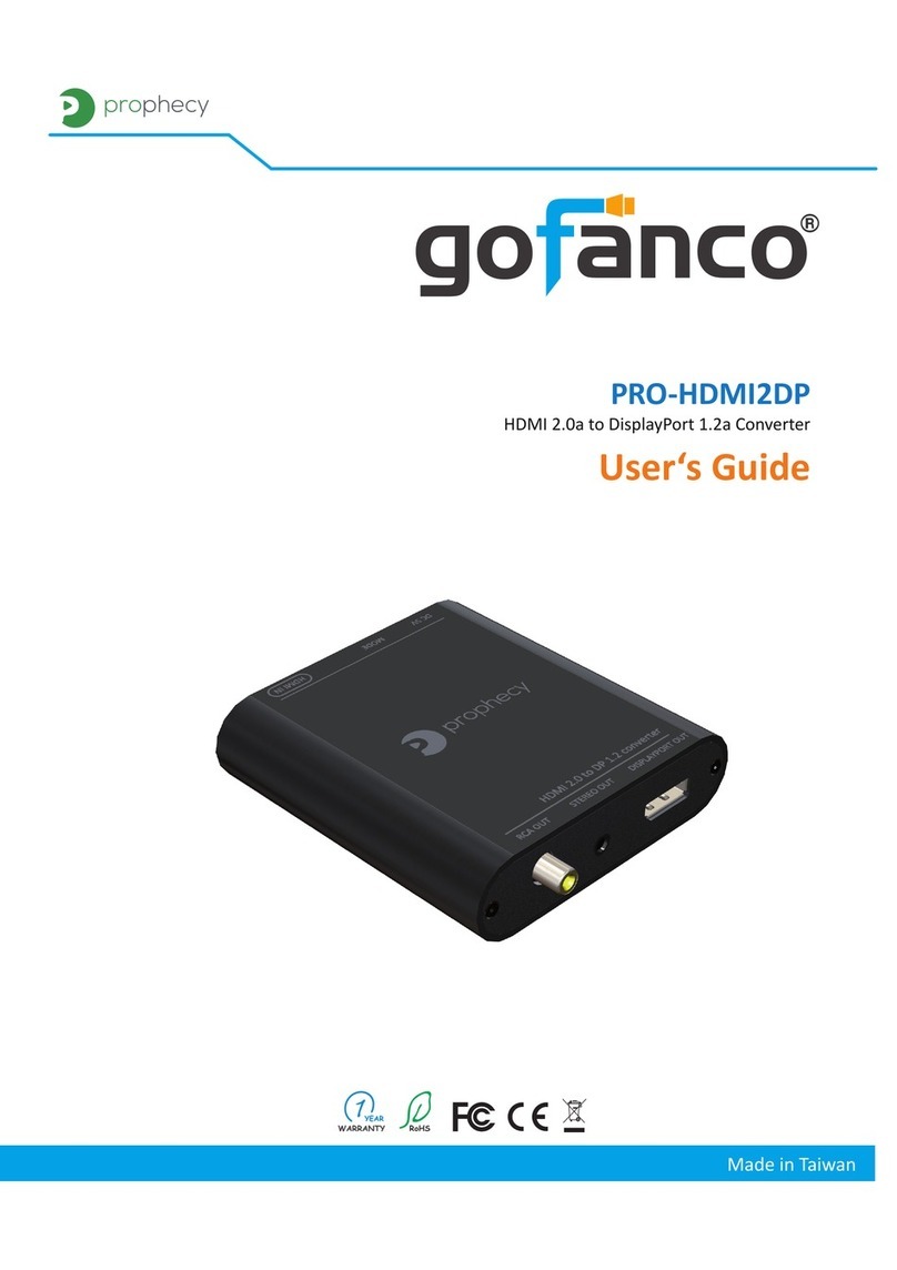
gofanco PRO-HDMI2DP user guide

Rockwell Automation
Rockwell Automation 1606-XLDF120E Reference manual
SWIT Electronics Co.,LTD.
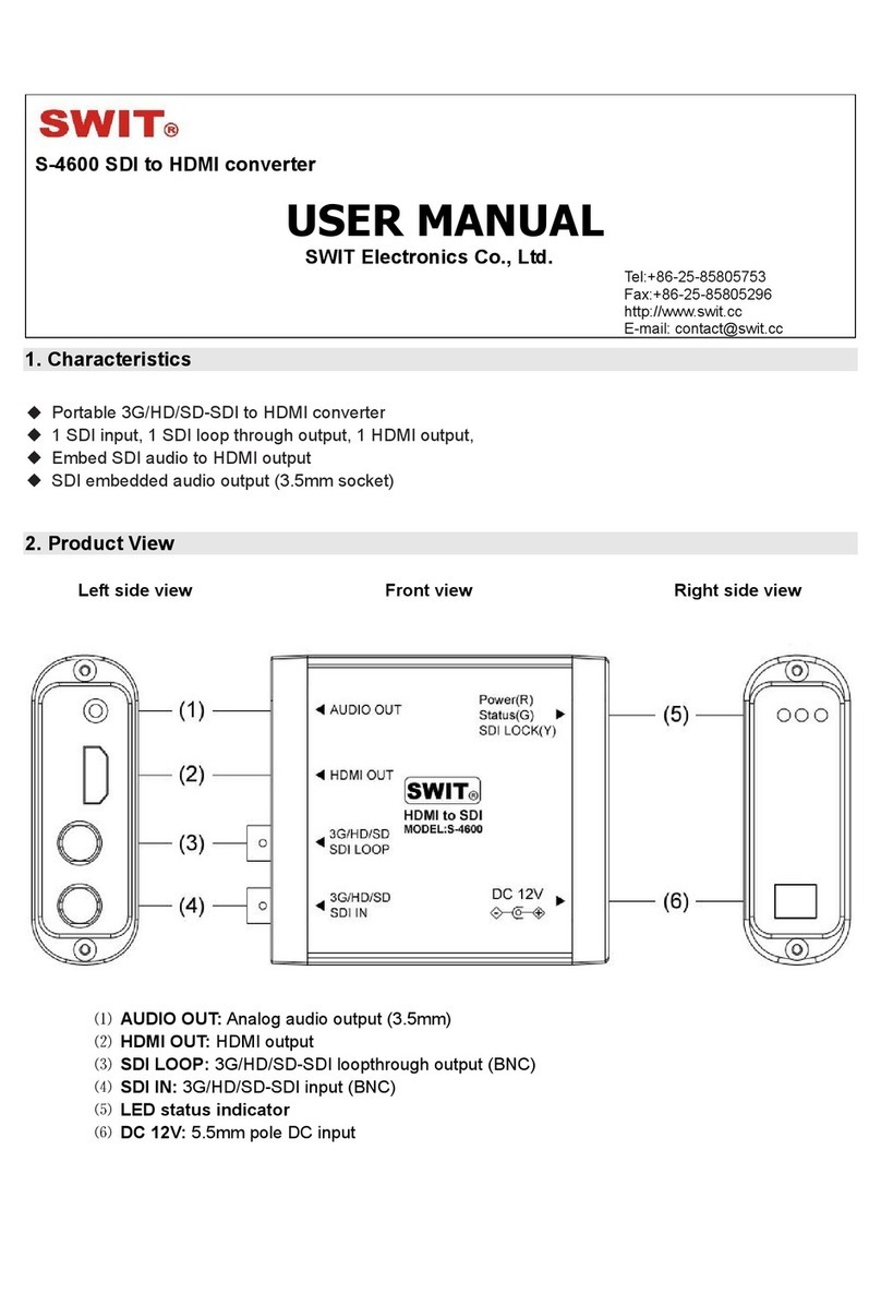
SWIT Electronics Co.,LTD. S-4600 user manual
Linear Technology
Linear Technology DC2050A manual
Gefen
Gefen EXT-GSCALER-PRON user manual

IMC Networks
IMC Networks MediaChassis/I-AC installation guide
