1
User Instructions for the
USB-311 and USB-312 "SmartWye"
PC USB Keyboard Encoders
Congratulations on your purchase of a VETRA USB Keyboard Encoder! This quality product is designed and built by us in
the USA and is backed by a VETRA Three-year Warranty and unlimited free technical support. We invite your comments,
please e-mail us at sales@vetra.com or call us at the numbers given at the end.
DESCRIPTION
The "SmartWye"äPC USB Keyboard Encoders make it easy to convert switch or contact closures to standard USB
keyboard codes for input to a PC’s USB port. The USB keyboard encoders enumerate as a standard HID keyboard, and
support USB bus suspend and remote wake-up. If enabled by the USB host, an input contact closure will generate a remote
wake-up signal on the USB bus. The USB Encoder model USB-312 contains an on-board USB hub providing an input for an
USB peripheral. If any device is connected to the hub, its current draw must not exceed 400 mA.
OPERATION
The encoder detects and debounces switch closures, generates appropriate key codes, and sends them to the PC. When the
switch is opened, the encoder sends a code indicating that the key is open.
GENERATED CODES
The USB Keyboard Encoder can generate one of four different USB keyboard code output configurations, selected by settings
of jumpers JP3 and JP4. Jumpers MUST BE set prior to applying power to USB Keyboard Encoder for correct keyboard code
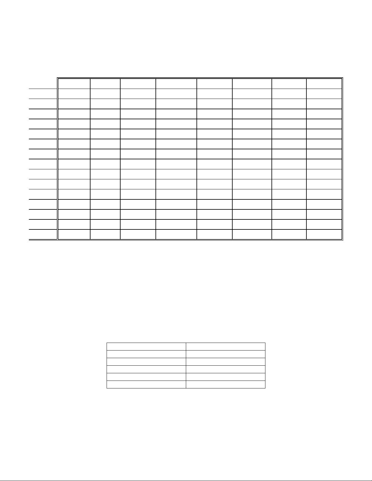
configuration outputs. The USB codes generated are shown in the table below:
Jumper JP3 Jumper JP4 Keyboard Code Configuration
Not Installed Not Installed USB-311/312 Matrix Key Codes, see Table 2
Installed Not Installed USB-311/312 Function Key Codes, see Table 1, column –24F
Not Installed Installed USB-311/312 Numeric Key Codes, see Table 1, column –24N
Installed Installed USB-311/312 Alpha Key Codes, see Table 1, column –24A
The keyboard code generated for a given switch closure is shown in the two tables (maps) below in terms of US keyboard key
cap legends. J3 is the switch input connector to the USB PC keyboard encoder.
The first table, Table 1, shows three standard maps for the keyboard encoder models that accept up to 24 discrete contact
closures to ground. The key code is generated when the J3 pin in the table is closed to the GND pin. The "A" (ALPHA) map
generates mostly alphabetic keys, the "F" (FUNCTION) map generates functions keys, and the "N" (NUMERIC) map
generates numeric keys.
Table 2 applies to matrix-connected switches, such as found on many membrane keypads. The matrix configuration of the
keyboard encoder contains the complete Windows 104 keys of the standard PC keyboard with switches connected in an 8 by
13 matrix.
PREPARE FOR OPERATION
1. Set-up: You can connect the "SmartWye" USB Keyboard Encoder to the PC at any time (plug-and-play). You do not
have to power-down the PC to make this connection. Use a standard USB Type A-B cable (may be purchased separately
from Vetra) to connect the keyboard encoder to any convenient USB port on the PC. The USB Keyboard Encoder is
powered from the PC via this cable. After plug-in, the Pc takes a short time to recognize (enumerate) the USB Keyboard
Encoder; then the USB Keyboard Encoder is ready for operation. Jumpers (JP3 and JP4) must be set prior to applying
power to the encoder board for correct keyboard code configuration. To set the encoder for a different key code output
configuration, the encoder must be unplugged from the PC, jumpers reconfigured and than plug the encoder back into
275 Marcus Blvd. Ste-J, Hauppauge, NY 11788-2022 USA
Tel: 800.537.9296 631.434.3185 Fax: 631.434.3516
www.vetra.com e-mail: sales@vetra.com