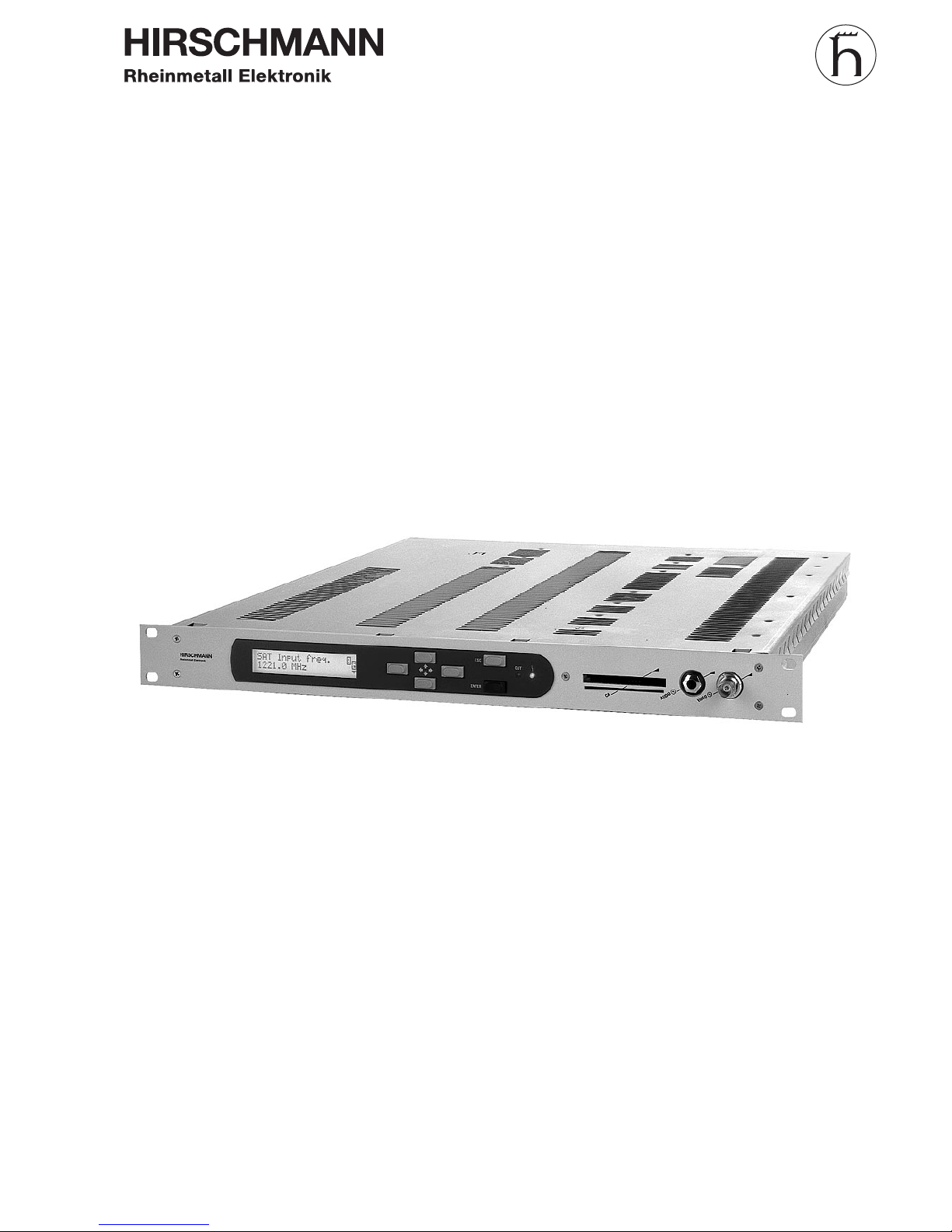
Hirschmann IRD 8500 User manual
Print: 1.0
Issue: October 2000
BH_8450E
IRD 8500/..
Operating manual
Integrated Receiver Decoder

Contents
Introduction 1-1
General notes....................................1-2
Technical modifications ...........................................1-2
Copyright .....................................................1-2
Explanation of warning and note symbols................1-2
Safety notes .....................................1-3
Explanation to digital TV broadcasting technique ..........1-4
General ......................................................1-4
Definitions ....................................................1-7
Putting into operation 2-1
Description ......................................2-2
General ......................................................2-2
Design .......................................................2-2
Power supply ..................................................2-3
Control .......................................................2-3
Monitoring ....................................................2-3
SAT-receiver/demodulator .........................................2-4
MPEG processing...............................................2-5
Conditional Access (Option) .......................................2-6
Video processing ...............................................2-6
Audio processing ...............................................2-7
Block diagram..................................................2-8
Interfaces and operating elements .....................2-9
Front-panel....................................................2-9
Rear-panel ...................................................2-10
Start-up........................................2-13
Procedure....................................................2-13
Contents
IRD 8500/..
0 - 2 Intergrated Receiver Decoder

Menu operation 3-1
Menu tree.......................................3-2
Menu operation...................................3-4
Operation .....................................................3-4
Change settings ................................................3-4
Alarm and warning messages ......................................3-5
Password protection .............................................3-5
Configuration / Identification .......................................3-6
Status display / history / operation log ................................3-6
Preset / Reset .................................................3-7
Network ......................................................3-7
Display.......................................................3-9
Date / Time / Temperature ........................................3-9
PIN-Code .....................................................3-9
Maintenance 4-1
Important notes...................................4-2
Functional check..................................4-3
Procedure ....................................................4-3
Nominal operation state ..........................................4-3
Help with problems ................................4-4
Change ........................................4-5
Changing the mains fuse..........................................4-5
Changing the battery.............................................4-5
Fitting of options ..................................4-7
General ......................................................4-7
Software update ..................................4-8
Handling........................................4-8
Storage ......................................................4-8
Transport .....................................................4-8
Disposal ......................................................4-8
Contents
IRD 8500/..
Intergrated Receiver Decoder 0 - 3

Ordering information ...............................4-9
Ordering information Integrated Receiver Decoder for 230 V mains connection ..4-9
Ordering information Integrated Receiver Decoder for 115 V mains connection ..4-9
Ordering information for options.....................................4-9
Services .......................................4-10
Changes 5-1
Appendix 6-1
General data ....................................6-2
Technical data ...................................6-2
Error messages ..................................6-6
Contents
IRD 8500/..
0 - 4 Intergrated Receiver Decoder

General notes
NOTE: Keep this manual handy at all times.
Technical modifications
Changes of information contained in this manual reserved.
Copyright
This manual contains information protected by copyright. All rights reserved. No part of
this manual may be photocopied, otherwise reproduced or translated into another
language without the prior written consent of Hirschmann.
Explanation of warning and note symbols
WARNING: Indicates that ignorance or neglicence of the recommended
cautionary measures may lead to personal injuries or
device damage.
ATTENTION: Indicates that ignorance or neglicence of the recommended
cautionary measures may lead to device damage.
NOTE: Useful tips and information on practical application.
Introduction
IRD 8500/..
1 - 2 Intergrated Receiver Decoder

Safety notes
WARNING: Improper use of electrical devices may result in electrical shocks !
ATTENTION: The IRD 8500/.. must be connected only to grounded mains !
ATTENTION: The mains cable must not be exposed to mechanical stress !
ATTENTION: The mains cable must be disconnected from the IRD 8500/.., if:
- the cable or the plug was damaged.
- a liquid was spilled onto the device
- the cabinet was damaged
Introduction
IRD 8500/..
Intergrated Receiver Decoder 1 - 3
Explanation to digital TV broadcasting technique
General
Objective With the help of data reduction by means of minimizing redundant moving picture in-
formation as well as flexible organisation of the signal quality, transmission capacity
shall be increased.
Realization First picture and sound data are reduced. Out of the compressed data streams a multi-
plex data stream is composed together with additional information (e.g. teletext).
The necessary methods for that are defined in the MPEG-2. For the additional infor-
mation only the syntactic frame is defined here. Which kind of data and in which way
data are to be integrated into the multiplex data stream is layed down by the European
DVP-project.
For decoding a high transmission quality and an approximative zero bit error rate must
be guaranteed. For digital modulation methods QPSK and QAM channel coding is
used. Through these methods a certain amount of bit errors can be corrected on the
receiver side.
The procedures for coding and transmission are defined by the European DVP-project.
MPEG-2 The MPEG-2 standard (ISO/IEC 13818) set up by the MPEG standardization commit-
tee regulates the coding of moving pictures and the accompanying sound.
DVB In addition to the transmission procedures defined by the MPEG-2 standard, the Euro-
pean DVB-project (Digital Video Broadcasting) has layed down a number of definitions
which were forwarded to the organisations ETSI / CENELEC for standardization.
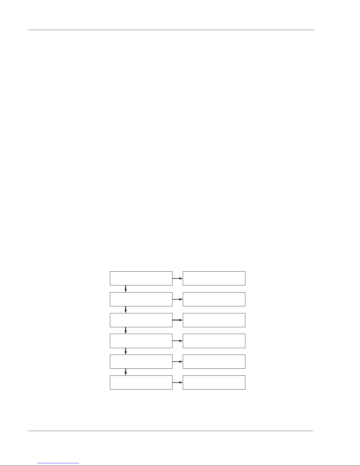
MPEG-decoding For decoding the MPEG data stream several steps are necessary.
For that different elements out of the data stream are used. ( see picture 1)
Introduction
IRD 8500/..
1 - 4 Intergrated Receiver Decoder
Transportstream Synchronisation
Reading out the Transportstream
Sync Byte 0x47
Program Specific Information
(PSI)
Selecting a program Packet Identifikation (PID)
Decoding Conditional Access Table (CAT)
Synchronisation Program
(VIDEO / AUDIO) Programm Clock Reference (PCR)
Time stamps (PTS + DTS)
Decoding additional data Service Information (SI)

Transport stream
synchronization
The transport stream packet consists of different substream data packets. The data
packets are transmitted with a length of 188 bytes. At the beginning of each packet is
the sync-byte (0x47). Because this value is not exclusively reserved for the sync-byte,
the repetetive occurrence of the sync-byte every 188 bytes has to be checked too to
ensure stable synchronization.
Packet identifying To identify the individual packets there is a Packet Identity (PID) contained at the be-
ginning of each packet (after the sync-byte). Each substream
(e.g. video, audio) gets its own PID. Some PIDs are assigned automatically and can-
not be changed. (e.g.: PAT, CAT , .. siehe table 1)
Structure of the transport
stream
Normally a transport stream contains several programs. Each of this program contains
again a number of different substreams (elementary streams).
Program access With the help of the information about the structure of a transport stream the required
program can be selected for decoding. If a program contains different equivalent ele-
mentary streams (e.g. different languages), the respective selection has to be made,
too. The selected elementary stream packets, which were detected by PID ,are passed
on from the demultiplexer to the decoder.
Decoding The encoding of the received data can take place on various levels.
The entire transport stream or elementary streams (Packetized Elementary Streams
PES ) can be encoded. The header information of the transport stream always stays
uncoded, the header information of the PES is also encoded when the entire transport
stream is encoded.
The data necessary for decoding are transmitted in the Entitlement Control Messages
(ECM) and in the Entitlement Management Messages (EMM).
The ECMs also contain the necessary keycodes and the EMMs also contain the ac-
cess codes for the receiver.
Program
synchronization
A program consists of several elementary streams. To synchronize the decoding of the
individual elementary streams a common reference is necessary.
For that a Program Clock Reference (PCR) is included in each elementary stream.
This information is contained in the Adaption Field, which is also transmitted in a cycle
of max. 100ms. The Adaption Field always stays uncoded.
The information derived from the PCR-data is used to control the 27 MHz system
clock of the receiver. In this way the synchronization of multiplexer and demultiplexer
is ensured.
For syncronizing the elementary streams additional time reference values, Decoding
Time Stamps (DTS) and Presentation Time Stamps (PTS) are contained in the ele-
mentary streams.
Introduction
IRD 8500/..
Intergrated Receiver Decoder 1 - 5

Data tables On the one hand, the tables are defined in the MPEG-2 standard and on the other
hand, they are specified from the DVB-project.
MPEG Program Specific Information (PSI):
PAT Program Association Table, contains information about the programs
in the transport stream.
PMT Program Map Table, contains information about the elementary
streams belonging to the program.
DVB Service Information (SI):
CAT Conditional Access Table, contains the necessary information for the
CA-module for decoding coded programs.
NIT Network Information Table, contains information about the included
programmes (e.g. frequency, modulation type, ...) of the distribution network
and the name of the distribution network.
SDT Service Description Table, describes the available programmes and
services of the distribution network.
EIT Event Information Table, an electronic TV-guide with identification of
programme start and age classification.
RST Running Status Table, contains status information about the individual
programmes.
TDT Time and Date Table, contains information about the current date and time
(UTC).
TOT Time Offset Table, contains information about the local date- and time-shift.
ST Stuffing Table, without content, is created when overwriting invalid tables.
BAT Bouquet Association Table, informs about the different programs of the
provider independent from the broadcasting area.
The PIDs of the tables are pre-assigned. the only exeption are the PMTs, whose PIDs
are defined in the PAT. To transmit different tables with one PID, each table contains
a Table_ID at the beginning.
Table PID Table_ID
PAT 0x0000 0x00
PMT 0x0020...0x1FFE 0x02
CAT 0x0001 0x01
NIT 0x0010 0x40...0x41
BAT 0x0011 0x4A
SDT 0x0011 0x42, 0x46
EIT 0x0012 0x4E...0x6F
RST 0x0013 0x71
TDT 0x0014 0x70
TOT 0x0014 0x73
ST 0x0010...0x0014 0x72
Introduction
IRD 8500/..
1 - 6 Intergrated Receiver Decoder

Definitions
MPEG Moving Pictures Experts Group: A standardization committee, whose task is the enco-
ding of moving pictures and sound information. Developed the basic standards for data
reduction. ( MPEG-1... MPEG-4 )
DVB Digital Video Broadcast: For digital broadcasting of TV-signals additional standards for
transmitting of MPEG-signals were defined.
Symbol rate Data rate of the applied digital signal on the input. For correct decoding the data rate
is to be set on the receiver.
Code rate According to the selected transmission path encoding is applied to ensure correct
transmission of the data signal. The code rate corresponds to the ratio between useful
data and total amount of data. The more additional data is transmitted, the better the
original useful signal can be restored in case of a transmission failure.
BER Bit Error Rate: The BER is measured by means of the Viterbi decoder. The BER
shows the ratio between the correctly received bits and the incorrect bits. For correct
processing of moving pictures the BER should not exceed a value of 1x10⁻⁵.
Multiplex Several Packetized Elementary Streams (PES) are multiplexed into a transportstream
(acc. to time-multiplex for MPEG2/Packetgeneration). A single PES contains the video,
audio and data information of a single programme.
The length of the transmitted packets are 188 or 204 bytes. In order to be able to
re-assign the individual packets on the receiver side, the packets are provided with a
programme identification.
C/N Carrier to Noise: Carrier to noise ratio of the input signal. For digital signals this value
includes the thermic noise and other distortions of the signal.
(e.g. intermodulation, phase-jitter, ...). It is very difficult to measure this value, it is cal-
culated back from the necessary correction expense.
In order to enable correct processing of moving pictures the C/N-ratio in connection
with the code rate of the input signal should achieve a BER smaller than 1x10⁻⁵
TS identifier Transport Stream identifikation: Each MPEG-transport stream has a unique descriptor.
This descriptor identifies a transport stream independently of transmission path and
frequency.
Demux state Demultiplexer status. The demultiplexer must adapt its signal processing clock to the
clock rate of the input signal. The necessary information for this is derived from the
MPEG-input signal. After successful syncronization the message “sync ok” occurs.
Introduction
IRD 8500/..
Intergrated Receiver Decoder 1 - 7

VPS Video Programming System. The VPS data is used for synchronization of recordings.
This data is integrated into line 16 of the baseband video signal.
Closed caption Using the TV-standard NTSC additional coded data can also be transmitted. For com-
plying with standards the function “Closed caption” must be used for signal integration.
Wide screen signalling If a PAL plus-signal is transmitted, the information about the currently sent picture size
(4:3, 16:9) is provided in line 23.
Common interface Defines a 64-pole interface for connection of a Conditional Access Module. The
CA-module is used for decoding encoded programmes.
CA Conditional Access: Several providers send their programmes encoded. In order to de-
code this programmes on the receiver side, a Conditional Access Card (hardware) of
the provider is needed. Together with the identification of the data in the MPEG-signal,
if the receiver supports this function, the signal can be decoded.
Smart-Card The smart card is supplied to the program receiver after obtaining the licence (Pay-TV)
or another valid authorization. On the smart card customer-specific data is stored. The
CA-module includes a smart-card reader. The releasing of decoding of programs hap-
pens via the digital data stream.
Introduction
IRD 8500/..
1 - 8 Intergrated Receiver Decoder
Description
General
The Integrated Receiver Decoder IRD 8500/QP serves for converting a QPSK SAT-
signal with MPEG-2 standard into a video-baseband-signal with the standard PAL,
NTSC or SECAM according to ITU-R BT624 (PAL-B/G). The audio signal is also con-
verted into the baseband. The IRD 8500/.. also supports the decoding of encoded data
(software option). All CA-modules which use the Common Interface are supported.
With its optional MPEG-interface an MPEG-input and an MPEG-output are also availa-
ble. With option LNB supply the supply voltage 13/18V and the control signal 22kHz
are available.
Design
View
The IRD 8500/.. is built as a 19" slide-in module with 1HU height.
The front-panel contains:
lthe display
lthe LED’s
lthe operating elements
lthe video monitoring output
lthe audio monitoring output
lopening to slide-in the Conditional Access Module
The rear-panel contains:
lthe mains connection
l1.SAT-IF input
lvideo-signal outputs
lRS232 interface
l10 Mbit Ethernet-interface
lremote monitoring interface ”ALARMS”
Cooling The IRD 8500/.. is cooled by convection.
Putting into operation
IRD 8500/..
2 - 2 Intergrated Receiver Decoder
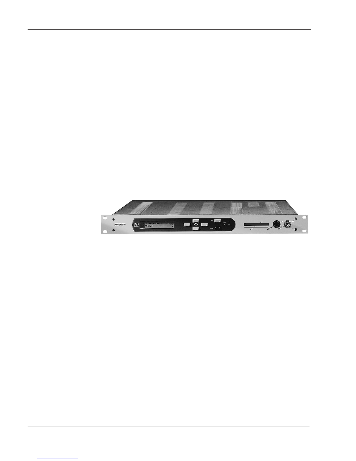
Integrated Receiver Decoder IRD 8500/..

Power supply
Depending on the model the IRD 8500/.. can be operated with the following mains vol-
tages:
l115 VAC
l230 VAC
ATTENTION: Before operation make sure that the mains voltage matches
the supply voltage indicated on the device.
The mains fuse is located beside the mains socket. The IRD 8500/.. does not have a
mains switch. To disconnect the IRD 8500/.. from the mains, the mains plug must be
pulled out of the device.
Control
General For controlling there are the following possibilities:
lKeypad and display on the IRD 8500/.. .(see chapter ”Menu operation”)
l10Mbit Ethernet-interface (software option “Network Access Control”)
lRS 232 Interface for stand-alone devices (software option “Network Access
Control”)
Remote control in a
network
(software option)
The IRD 8500/.. can be remote controlled via the Ethernet- or RS232-interface. A stan-
dard WWW-browser with TCP/IP protocol (e.g. Internet Explorer) is to be used. The
remote control can be disabled on the IRD 8500/.. .
Monitoring
General For monitoring there are the following possibilities:
lkeypad and display
lLED’s ”f” and ”OUT” (see interfaces and operating elements)
lMonitoring output ”VIDEO m”, monitoring output ”AUDIO m”
l10 Mbit Ethernet-interface (software option “Network Access Control”)
lRS 232 Interface for stand-alone devices (software option “Network Access
Control”)
lRemote monitoring interface ”ALARMS”
lHistory / operation log (see menu operation)
lStatus display (see menu operation)
Remote monitoring interfa-
ce ”ALARMS”
On the remote monitoring interface ”ALARMS” the status messages ”ALARM” and
”WARNING” are signalled via two floating double-throw contacts.
To the floating double-throw contacts external error indicators ( e.g. siren, lamp) can
be connected. The pin-assignment is shown in chapter ”Interfaces and operating ele-
ments”.
Putting into operation
IRD 8500/..
Intergrated Receiver Decoder 2 - 3

SAT-receiver/demodulator
Input frequency
menu
”Input frequency"
”Input level"
”Frequency offset”
”Tuner status”
The input frequency can be adjusted in a range from 920 ... 2150 MHz in steps of 0,1
MHz. The current signal strength as well as the frequency offset of the input signal can
be queried. The displayed frequency offset is defined as follows: offset = received fre-
quency - set frequency. The software is tracking the frequency, until the tuner is lo-
cked. The current status (locked/unlocked) can be queried. For monitoring a warning-
and an alarm threshold can be defined for each parameter.
Symbol rate
Menu ”Input symbol rate”
The symbol rate of the input signal is to be adjusted according to the input signal. It
can be set in a range from 4 ... 45 MSymb/s in steps of 0,1 kSymb/s.
Transport stream
Menu ”TS identifier”
When entering a SAT-input frequency a search starts in a range of ±8MHz of the set
mid-frequency to find present transport streams. The transport stream identifier (ID)
and the input frequency of the transport streams are displayed.
Unique identification of a transport stream is only possible with the TS ID.
The displayed input frequency of a transport stream can vary about the frequency de-
viation of the LNC-oscillator.
The desired transport stream is to be selected from the available transport streams.
Bit Error Rate
Menu
”Input BER after V.”
The BER of the MPEG-signal can be queried after the Viterbi-decoding.
A warning- or an alarm threshold can be defined.
Code rate input signal
Menu ”Input code rate”
The code rate of the input signal can be queried. The code rate can be monitored by
defining a warning- or an alarm message.
Carrier to noise
Menu ”Input C/N”
The C/N-ratio of the input signal is measured and can be queried. A warning- or an
alarm threshold can be defined.
LNB remote supply
Menu “LNB supply”
With the option “LNB supply” this menu is displayed. The LNB remote supply is used
for the direction of the polarity and is available with 13V (vertical) or 18V (horicontal).
LNB control
Menu “LNB 22kHz”
With the option “LNB supply” this menu is displayed. The 22kHz control signal is used
for the selection of the receiving frequency band.
Putting into operation
IRD 8500/..
2 - 4 Intergrated Receiver Decoder

MPEG processing
MPEG-input
Menu ”MPEG input”
According to the desired source of the MPEG-signal, the MPEG input has to be
pre-selected. There are following possibilities available:
lSAT
lSPI
lTSI (only with the option “MPEG interface” available)
Program selection
Menu ”Select service”
The programmes present in the transport stream are displayed. The desired program-
me must be selected. In order to read the entire displayed text for long programme
descriptions, the text can be scrolled (see menu operation).
In the beginning of each programme description a symbol is positioned which shows
the current status of decoding.
The following indications are possible:
l”#” encoded programme
l”?” programme is not decoded correctly
l”+” programme is decoded correctly
When changing a programme, a programme interruption occurs for approx. 2sec. du-
ring re-initialization.
Demultiplexer and
decoder status
Menu
”Demux status”
”Decoder status”
If the demultiplexer is synchronized with the MPEG-input data stream, ”sync ok” is dis-
played. If the decoder can decode the signal correctly, ”play” is displayed, otherwise
”idle” is displayed. Monitoring of the corresponding states can be done by setting war-
ning- or alarm messages.
Test lines
Menu ”Test lines”
The test lines pre-assigned for the respective standard ( see Appendix / Technical
data) can be switched off.
VPS data, sound status
Menu ”VPS”
The VPS-data as well as the sound status (mono/stereo/2-tone) present in the MPEG-
input signal are inserted into the data line 16. The VPS-data can be switched off.
Teletext
Menu ”Teletext”
Teletext data present in the MPEG-input signal can be inserted into the video signal.
Closed captioning
Menu ”Closed caption”
For NTSC, data of the MPEG-signal coded in the picture can be transmitted. This
function can be switched off.
Wide screen
Menu ”Wide screen sign.”
For PAL-plus the information ”wide screen signalling” is inserted into line 23, if a corre-
sponding picture format is present at the input. This function can be switched off.
Putting into operation
IRD 8500/..
Intergrated Receiver Decoder 2 - 5

Conditional Access (Option)
Selection CA-
applications
Menu ”CA-applications”
Applications available on the CA-card can be queried. The application for the desired
programme is to be selected.
CA-card menu
Menu ”CA-menu”
Menus available on the card can be selected here. The description of the menu items
can be found in the documentation of the CA-card.
Video processing
Image format
Menu
”Format processing”
The format of the output image of the IRD 8500/.. is set with 4:3.
If a 16:9 input format is present, adaptation to the output format can be set in 3 diffe-
rent ways:
lpass-through (not defined output image)
lletter box (vertical filter, black bar on the upper and lower image margin)
lpan & scan (expanding to the total image height, trimming the left and right
margin)
Test signal
Menu ”Color bar”
The IRD 8500/.. provides a EBU color bar testsignal 100%.
Output switch-off
Menu ”Video output ”
The video baseband output can be switched off. Switch-off of the output signal is re-
commended when settings are changed on the IRD 8500/.. .
TV Standard For the baseband video signal the following TV-standards are available:
Menü ”Video mode” lPAL
lNTSC
lSECAM
If the TV-standard is changed, a warm reset is performed on the IRD 8500/.. .
Putting into operation
IRD 8500/..
2 - 6 Intergrated Receiver Decoder

Audio processing
Language selection
of the sound
Menu ”Select language”
The language of the sound can be selected in the menu. When changing the langua-
ge, the programme is interrupted for approx. 2 seconds.
Selection of the mode
of the sound
The audio baseband output can be selected from the following possibilities:
Menu ”Audio Mode” lMono
lStereo
l2-Tone R
l2-Tone L
The selection of the audio baseband signal does not influence the sound coding
(mono, stereo, 2tone) carried out by the MPEG input signal.
Mute switching of the
audio signal
Menu ”MUTE”
The audio base band signal can be switched off.
Audio output level
Menu ”Audio level”
The output level can be adjusted in a range from -3 ... 12 dBm (600 ohm) in steps of
minimum 0,1 dB.
Putting into operation
IRD 8500/..
Intergrated Receiver Decoder 2 - 7

Block diagram
Putting into operation
IRD 8500/..
2 - 8 Intergrated Receiver Decoder
1st SAT-IF e
AUDIO a
AUDIO m
VIDEO a
VIDEO a
VIDEO m
DA
Video -
Encoder
FPGA
MPEG-
Decoder
MPEG-
Demux
Data
Latch
Data
Latch
Common
Interface CI
SAT-
Demodulator
Option
MPEG-
Interface
mC
to Conditional
Access Module
MPEG SPI
input
MPEG SPI/ASI
output
TTX
OUT
LCD/
Keyboard
RS 232
Alarms
Ethernet
Monitoring/
Control
Power Supply
230/115 VAC
Block diagram Integrated Receiver Decoder with option MPEG-interface

Interfaces and operating elements
Front-panel
View
[1] Display (two lines with 20 characters each)
[2] Cursor keys
[3] ESC-key
[4] ENTER-key
[5] LED ”OUT” lights up green, if input signal is correctly processed and an output
signal is present.
[6] LED ” f” lights up red in case of an alarm or hardware error. In addition the dis-
play shows which error occured ( e.g. ”ERROR: sync nok”).
[7] Slide-in place for Conditional Access Module
[8] AUDIO-monitoring output ”AUDIO m” (6.3mm jack socket; 600 ohm)
[9] VIDEO-monitoring output ”VIDEO m” (BNC-socket 75 ohm)
Putting into operation
IRD 8500/..
Intergrated Receiver Decoder 2 - 9
[1] [3]
[4][5]
[2] [6]
[7] [8] [9]
OUT
ESC
ENTER
AUDIOm
CA
VIDEOm
Integrated Receiver Decoder IRD 8500/..

Rear-panel
View
[1] 1. SAT-IF input ”SAT IF e” (F-socket)
[2] VIDEO output ”VIDEO a” (BNC-socket; 75 ohm)
[3] VIDEO output ”VIDEO a” (BNC-socket; 75 ohm)
[4] left audio baseband output ”AUDIO L a” (XLR-socket, 3-poles)
[5] right audio baseband output ”AUDIO R a” (XLR-socket, 3-poles)
[6] Serial output “ASI a” (BNC-socket, 75 ohm)
[7] Parallel output “SPI a” (25-pole sub-D-socket)
[8] Parallel input “SPI e” (25-pole sub-D-socket)
[9] remote monitoring interface ”ALARMS’ (9-pole sub-D-socket)
[10] ”RS 232" interface (9 pole sub-D-socket)
[11] 10 Mbit Ethernet-interface ”10BASE-T” (RJ-45 Stuart connector)
[12] LED ”LINK” (lights up when Ethernet connection is electrically correct)
[13] mains connection ”MAINS”
[14] mains fuse
Putting into operation
IRD 8500/..
2 - 10 Intergrated Receiver Decoder
[1] [3] [4] [5] [6] [7] [8]
[9]
[2] [10] [11]
[12] [13] [14]
SAT IFeVIDEOaVIDEOa
AUDIO L
a
AUDIO R
a
RS 232
10BASE-T MAINS
230V -/315mAT
115V -/630mAT
LINK
ALARMS
ASI
SPI SPI e
Integrated Receiver Decoder IRD 8500/..
This manual suits for next models
4
Table of contents
Other Hirschmann Media Converter manuals


