System calibration
Calibration is an essential operation that completes readhead set-up,
with the optimum incremental and reference mark signal settings
stored in the readhead non-volatile memory.
Before system calibration, install the readhead to maximise
the signal strength throughout the axis travel.
NOTE: CAL routine maximum speed <100 mm/s
Step 1 – Incremental signal calibration
uEnsure Automatic Gain Control is switched off
(CAL LED on readhead is not illuminated)
before beginning calibration.
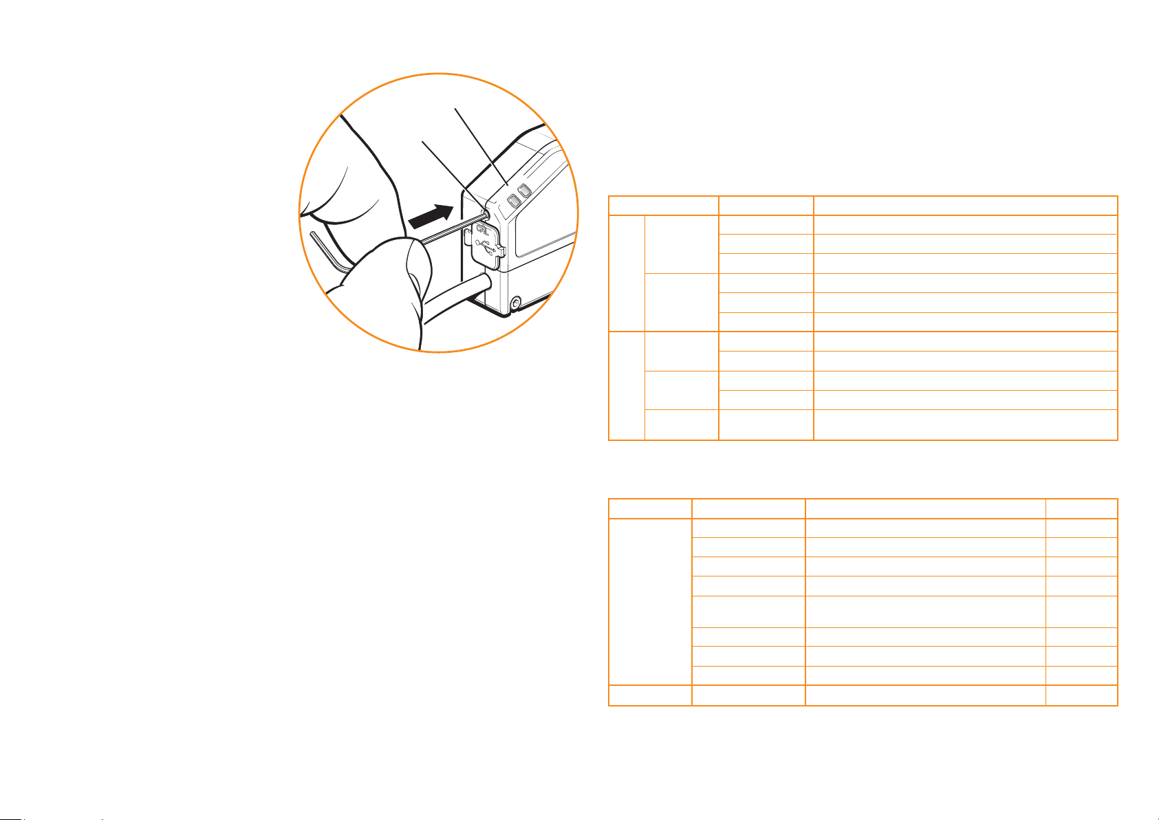
uPress and release the CAL button on the
end of the interface as shown.
u The CAL LED will now periodically single-ash
to indicate that it is in incremental signal
calibration routine.
u Move the axis at slow speed, ensuring you do not
pass the reference mark. The CAL LED will
double-ash periodically, indicating the incremental
signal is now calibrated and the new settings are
stored in the readhead memory.
uThe system is now ready for reference mark phasing.
NOTE: For systems without a reference mark, go to ‘Calibration routine - manual exit’
Step 2 – Reference mark phasing
u Move the axis until the reference mark passes the readhead optical centre in any direction,
the CAL LED will continue to double ash periodically.
u Move the readhead back over the selected reference mark; the CAL LED will stop ashing and
remain off. The reference mark is now phased.
u The system automatically exits the CAL routine and is ready for operation.
Calibration routine - manual exit
u To exit the calibration routine at any time press and release the CAL button.
u
The CAL LED will stop ashing and remain off.
u If step 1 is complete (CAL LED is periodically double-ashing) the incremental signal CAL settings
will be stored.
u
Reference mark phasing settings will not be stored for CAL manual exit.
u
If the calibration routine has not been completed, restore factory defaults and then repeat the full
calibration.
Restoring factory defaults
When re-installing the system, or in the case of incomplete calibration, the factory defaults
should be restored.
To restore factory defaults;
uSwitch system off.
uPress and hold the CAL button whilst switching the system on. The CAL LED on the readhead
will ash several times, indicating that the factory defaults have been restored.
uRelease CAL button.
u Check the ‘Readhead mounting/installation’ and re-calibrate the system.
NOTE: System must be re-calibrated after restoring factory defaults.
NOTE: The LED on the interface will flash blank when the reference mark is detected
(<100 mm/s only). It indicates the presence of a reference mark not the phasing status.
Switching Automatic Gain Control on or off
AGC can be switched on or off via the DOP interface CAL push button switch.
uPress and hold the CAL button on the interface for >3 seconds to switch AGC on or off.
The CAL LED on the readhead will be illuminated when AGC is active.
NOTE: The system must be calibrated before switching AGC on.
Txxxx Readhead LED diagnostics
Normal set-up: signal level 70% to 135%
Acceptable set-up; signal level 50% to 70%
Poor set-up; signal may be too low for reliable operation; signal level <50%
Normal phasing
Acceptable phasing
Poor phasing; recalibrate
Automatic Gain Control – On
Automatic Gain Control – Off
Calibrating incremental signals
Calibrating reference mark
Restoring factory defaults
Status
Set-up
CAL
LED Indication
Incremental
Reference mark
Operating
Calibration
Reset
Green
Orange
Red
Green (ash)*
Orange (ash)
Red (ash)
On
Off
Single ashing
Double ashing
Flashing at
power-up (<2s)
DOP interface set-up LED diagnostics
Normal setup; signal level 110% to 135%
Optimum setup; signal level 90% top 110%
Normal set-up: signal level 70% to 90%
Acceptable set-up; signal level 50% to 70%
Poor set-up; signal may be too low for reliable operation;
signal level <50%
Over signal; system in error
Over speed; system in error
Poor set-up; signal level <20%; system in error
Reference mark detected (speed <100mm/s only)
Status
Signal Alarm output*
Indication
Incremental
Reference mark
Purple
Blue
Green
Orange
Red
Purple / blank - ashing
Blue / blank - ashing
Red / blank - ashing
Blank ash
No
No
No
No
No
Ye s
Ye s
Ye s
No
*-Alarm output will take the form of 3-state or line driven E signal depending on interface conguration.
Also, some congurations do not output overspeed alarm. See TONiC DOP Data Sheet (L-9517-9411) for details of interface conguration.
-Momentary status only, while fault condition remains.
-Alarm may result in axis position error, re-datum to continue.
*Flash will effectively be invisible when incremental signal level is >70% when passing reference mark.
CAL button
Set-up LED
{