Hirschmann OZDV 2471 P Manual

Beschreibung und Betriebsanleitung
Optischer Schnittstellenwandler
Description and Operating Instructions
Optical interface converter
Description et manuel d’utilisation
Convertisseur interface optique
OZDV 2471 P
Schnittstellenwandler V.24/LWL;
asynchron, vollduplex
Spannungsversorgung wahlweise durch das
angeschlossene Endgerät oder über
Steckernetzteil möglich
Überbrückbare Entfernungen
≤100 m mit Kunststoff-LWL
≤6700 m mit Quarzglas-LWL
Bitrate: DC bis 20 kbit/s
Kompakte Aufsteckmodule in stabilem
Metallgehäuse
V.24/Fibre optic interface converter;
asynchronous, full duplex
Power supply either via the connected
terminal device or via plug-in power supply
Maximum transmission distance
≤100 m using plastic fibre
≤6700 m using quartz glass fibre
Bit rate: DC - 20 kbit/s
Compact plug-in modules housed in stable
metal cases
Convertisseur interface V.24/guide d’ondes
lumineuses; asynchrone, duplex intégral
Tension d’alimentation possible au choix par
l’appareil terminal connecté ou par le bloc
d’alimentation à connecteur
Distances de transmission:
≤100 m avec guide d’ondes lumineuses en
plastique
≤6700 m avec guide d’ondes lumineuses en
verre quartzeux
Taux de bit: DC jusqu’à 20 kbits/s
Modules enfichables compacts dans un boî-
tier en métal solide
Bestell-Nr. / Ord. code / N° de cde.
943 340-021
OZDV 2471 G
Bestell-Nr. / Ord. code / N° de cde.
943 341-021
,
,
,,
,,,
,,,
,,
,
,,
,
,,
,,,

2
Inbetriebnahme
Betriebsarteneinstellungen
Überprüfen und korrigieren Sie bei Bedarf
folgende Einstellungen:
– Umschaltung „für DTE/für DCE”-Betrieb
– Verbindung Schirmmasse mit Signalmasse
– Wahl der Spannungsversorgung.
Umschaltung „für DTE/für DCE”-Betrieb
Je nach Erfordernis des angeschlossenen
Endgerätes können Sie mit den Schiebe-
schaltern S1(braun) und S2(rot) zwischen
„für DTE”- und „für DCE”-Betrieb umschalten.
(Informationen hierzu finden Sie im Handbuch
des anzuschließenden Endgerätes.)
Schieben Sie zum Umschalten die
Schiebeschalter mit einem spitzen
Gegenstand in die entsprechende Stellung.
„für DTE”-Betrieb
(werkseitig eingestellt)
„für DCE”-Betrieb
Verbindung Schirmmasse mit Signal-
masse
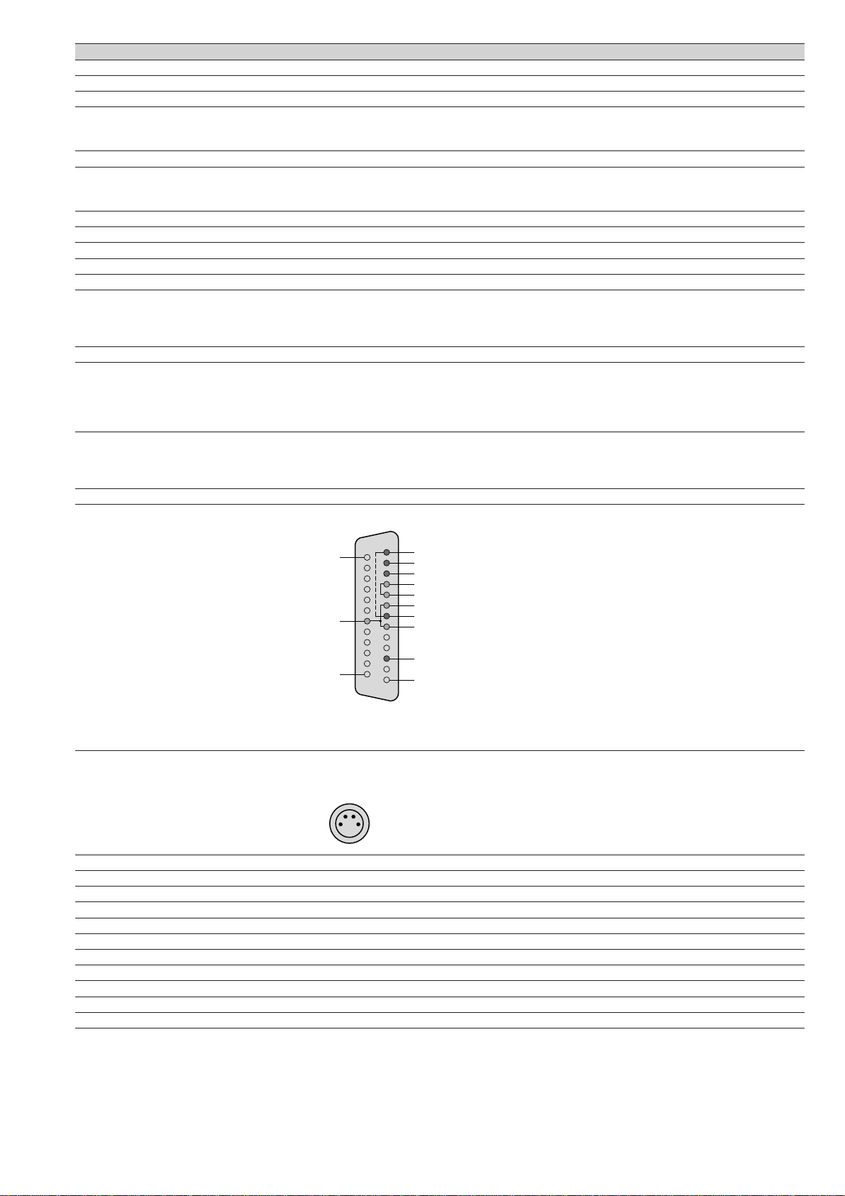
Bei Bedarf können Sie die Schirmmasse (Pin
1 des 25poligen Sub-D Steckverbinders) mit
der
Signalmasse/Spannungsversorgungsmasse
(Pin 7) mit dem Schiebeschalter S3(orange)
galvanisch verbinden.
ABCD
1234
ABCD
1234
Schieben Sie zum Umschalten den
Schiebeschalter mit einem spitzen
Gegenstand in die entsprechende Stellung.
Pin 1 und Pin 7 getrennt
(werkseitig eingestellt)
Pin 1 und Pin 7 verbunden
Wahl der Spannungsversorgung
Wünschen Sie statt der
Spannungsversorgung über ein
Steckernetzteil eine Spannungsversorgung
vom angeschlossenen Endgerät über den
25poligen Sub-D-Steckverbinder (Pin 11), so
ist dies durch Umschalten von
Schiebeschalter S4(gelb) möglich.
Schieben Sie zum Umschalten den
Schiebeschalter mit einem spitzen
Gegenstand in die entsprechende Stellung.
Spannungsversorgung
über Steckernetzteil
(werkseitig eingestellt)
Spannungsversorgung
über Pin 11
ABCD
1234
ABCD
1234
ABCD
1234
ABCD
1234
LWL-Kabelverbindung
Verbinden Sie die beiden Schnittstellen-
wandler durch ein Duplex-LWL Kabel mit
BFOC (ST®) Steckverbindern.
Achten Sie bitte darauf, daß jeweils ein
Eingang (IN) und ein Ausgang (OUT) miteinan-
der verbunden sind („Überkreuzverbindung“).
Aufstecken
Stecken Sie den 25 poligen Sub-D
Steckverbinder (male) des
Schnittstellenwandlers auf den entsprechen-
den Anschluß am Endgerät und arretieren Sie
ihn mit den beiden Rändelschrauben.
Betriebsstörungen
In folgenden Störungsfällen gehen die elektri-
schen Ausgänge der Schnittstellenwandler in
den High Pegel:
– Zweiter Schnittstellenwandler nicht auf
Endgerät gesteckt;
– Zweites Endgerät ausgeschaltet.
Sind die optischen Steckverbinder am
Schnittstellenwandler OZDV 2471 P/G nicht
gesteckt, so kann – insbesondere bei hoher
Umgebungshelligkeit – ein rein zufälliges
Signal an den elektrischen Ausgängen anlie-
gen.
Zubehör
Steckernetzteil SNT 510
Bestell-Nr. 268 109-001
Beschreibung
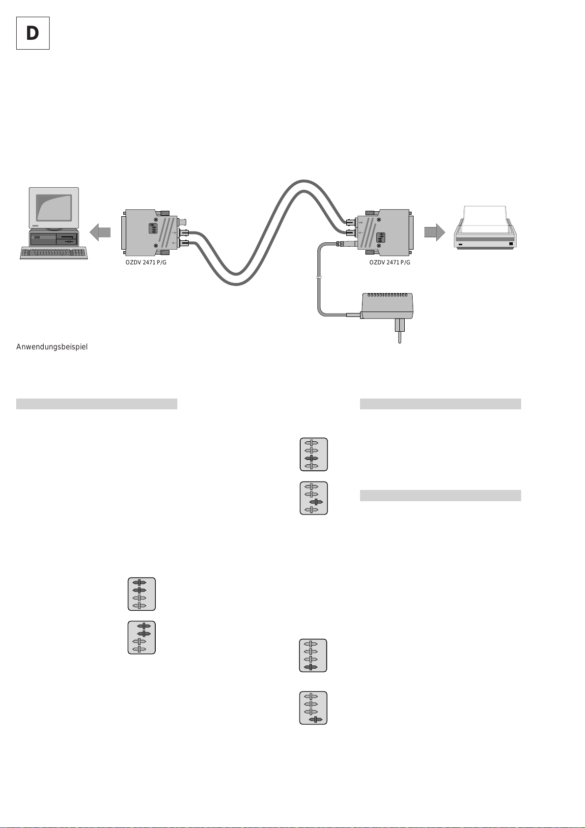
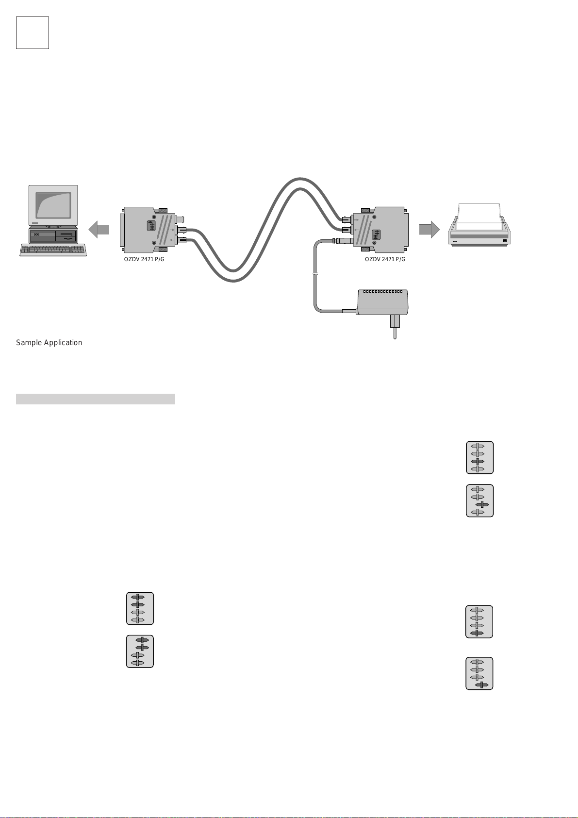
Eine Übertragungsstrecke, bestehend aus
zwei Schnittstellenwandlern OZDV 2471 P
oder OZDV 2471 G und einem Duplex-Licht-
wellenleiter, ermöglicht eine störsichere, op-
tische Datenübertragung von V.24 (RS-232 D)
Signalen über eine Entfernung von bis zu
6700 m.
Die Übertragungsstrecke arbeitet im asyn-
chronen Vollduplex-Betrieb. Sie ersetzt alle
konventionellen Vierdraht-Verbindungslei-
tungen. Die Datenübertragung erfolgt über
zwei optische Fasern, somit müssen die ange-
schlossenen Endgeräte für Software-Hand-
shake (X on/X off-Übertragung) geeignet sein.
Dies ist in den jeweiligen Handbüchern der
anzuschließenden Endgeräte angegeben.
Der mechanische Aufbau der Schnittstellen-
wandler erfolgt als kompakte 25polige Sub-D
Steckverbinder, die die gesamte Elektronik
enthalten.
Die Spannungsversorgung der Schnittstellen-
wandler erfolgt wahlweise durch das ange-
schlossene Endgerät über den Sub-D-
Steckverbinder oder über ein Steckernetzteil.
Die Schnittstellenwandler sind sowohl „für
DTE“- (Data Terminal Equipment) als auch „für
DCE“- (Data Communication Equipment)
Betrieb geeignet. Durch einen Schiebeschalter
sind sie auf den jeweiligen Betriebszustand
des anzuschließenden Endgerätes (siehe
Handbuch) einstellbar.
Durch eine vollständige DC-Kopplung der
Schnittstellenwandler ist gewährleistet, daß
sofort beim Einschalten der Endgeräte der
richtige Zustand übertragen wird und beliebig
lange Übertragungspausen problemlos mög-
lich sind.
Durch einen Schiebeschalter kann die Schirm-
masse mit der Signalmasse verbunden werden.
,,
,,,,
,,
,,
,,
,,
,,,,
,,
,,
,,
,,
,,
,,,,
,,
,,
,,
,
,,
,,,,
,,
,,
,,
,
OZDV 2471P/G OZDV 2471P/G
Anwendungsbeispiel
D

3
Technische Daten 1)
Typ OZDV 2471 P OZDV 2471 G
Betriebsspannung 5 V ±5%
Stromaufnahme (typ./max.) 90 mA/120 mA
V.24-Schnittstelle
Eingangsignal
– HIGH (min./max.) –30 V/–3 V
– LOW (min./max.) +3 V/+30 V
Eingangsimpedanz > 3 kΩ
Ausgangssignal (V.24 (RS-232 D)-Pegel)
– HIGH (min./max.) –15 V/–5 V bei 3-7 kΩLastwiderstand
– LOW (min./max.) +5 V/+15 V bei 3-7 kΩLastwiderstand
Flankensteilheit (max.) 30 V/µs
Bitrate DC bis 20 kbit/s (DC-Kopplung)
Bitfehlerhäufigkeit < 10-9
Optische Schnittstelle
Wellenlänge 665 nm 860 nm
Einkoppelbare optische Leistung
– in 50/125 µm Faser – 30 µWss, –15 dBm
– in 62,5/125 µm Faser – 60 µWss, –12 dBm
– in 980/1000 µm Faser 250 µWss, –6 dBm –
Empfindlichkeit Empfänger –38 dBm –40 dBm
Überbrückbare Entfernung mit 2*)bzw. 3**)dB
Systemreserve/Streckendämpfung
– mit 50/125 µm Faser (3,0 dB/km) – 0 bis ≥6700 m**)/23 dB
– mit 62,5/125 µm Faser (3,5 dB/km) – 0 bis ≥6600 m**)/26 dB
– mit 980/1000 µm Faser (0,24 dB/m) 0 bis ≥100 m*)/29 dB –
Schiebeschalter S11: „für DCE“-Betrieb A: „für DTE“-Betrieb
S22: „für DCE“-Betrieb B: „für DTE“-Betrieb
S33: Pin 1 und Pin 7 verbunden C: Pin 1 und Pin 7 getrennt
S44: Spannungsversorgung über Pin 11 D: Spannungsversorgung über Steckernetzteil
Anschlüsse
Data 25poliger Sub-D-Steckverbinder, male
Beschaltung „für DTE“-Betrieb Eingang: Pin 2 (TxD), Ausgang: Pin 3 (RxD)
Beschaltung „für DCE“-Betrieb Eingang: Pin 3 (RxD), Ausgang: Pin 2 (TxD)
Betriebsspannung
intern über 25poligen Sub-D-Steckverbinder (Pin 11)
extern über 4polige Kleinspannungsbuchse; Bauform: M8 nach IEC 947-5-2
Opto BFOC (ST®) 2,5
EMV-Schutz
Störaussendung Erfüllt EN 55011, Grenzwertklasse B
Störfestigkeit Erfüllt IEC 801-2, -3, -4
Allgemeine Daten
Umgebungstemperatur 0 °C bis +50 °C
Lagerungstemperatur –20 °C bis +70 °C
Relative Luftfeuchtigkeit 10% bis 90% (nicht kondensierend)
Masse 110 g
Gehäusewerkstoff Zink-Druckguß
Abmessungen B x H x T 56 x 17 x 80 mm
1) Technische Daten die nur beim Typ OZDV 2471 P aufgeführt sind gelten auch für den Typ OZDV 2471 G
1
13
14
20
25
PGND
2 TxD/RxD
3
4
5
6
8
RxD/TxD
7 GND
11 Externe Versorgung
PGND Protective Ground
TxD Transmit Data
RxD Receive Data
GND Ground (Data)
4
3
2
1
1NC
2 +5 V
3NC
4 Masse

GB
4
Setting up
Operational settings
Check and, if necessary, adjust the following
settings:
– DTE/DCE selection
– Protective ground/signal ground connec-
tion
– Power supply selection
DTE/DCE selection
According to the specific requirements of the
connected equipment the module may be
switched to either DTE (Data Terminal
Equipment) or DCE (Data Communications
Equipment) operation using the slide switches
S1(brown) and S2(red) (information is con-
tained in the documentation of the terminal
equipment used).
Use a pointed object to push the switches to
the desired position.
“for DTE” operation
(factory setting)
“for DCE” operation
Protective ground/signal ground
connection
If required, the protective ground (pin 1 of the
ABCD
1234
ABCD
1234
25-pin Sub-D connector) can be electrically
connected to the signal/power supply ground
(pin 7) by switch S3(orange).
Use a pointed object to push the slide switch
to the desired position.
Pin 1 not connected to pin 7
(factory setting)
Pin 1 connected to pin 7
Power supply selection
If you wish power to be supplied via the
25-pin Sub-D connector (pin 11) instead of by
a plug-in power supply, you can change the
setting with slide switch S4(yellow).
Use a pointed object to push the slide switch
to the desired position.
Power supply via
plug-in power supply
(factory setting)
Power supplied
via pin 11
ABCD
1234
ABCD
1234
ABCD
1234
ABCD
1234
Description
A transmission link consisting of two
OZDV 2471 P or OZDV 2471 G interface
converters and a duplex optical fibre can
provide interference-free optical data trans-
mission of V.24 (RS-232 D) signals over dis-
tances of up to 6700 m.
The transmission link operates in asynchro-
nous full duplex mode and can replace all
conventional 4-wire connections.
Data transfer takes place through two optical
fibers. For that reason, the terminal equipment
must be able to handle software handshaking
(X on/X off transmission).
The information as to whether a terminal device
supports software handshaking can be found
in the appropriate manuals for the device in
question.
Mechanically, the interface converters are
built into compact 25-pin Sub-D connectors
which house all electronic components.
Power supply of the interface converters
occurs either via the connected terminal devi-
ce and the Sub-D connector or via a plug-in
power supply.
The interface converters are suited for both
DTE (Data Terminal Equipment) and DCE
(Data Communication Equipment) use.
A slide switch is provided for setting the
converters to the individual terminal device's
operational mode (refer to the appropriate
manual).
Complete DC coupling of the modules gua-
rantees that the correct status is immediately
transmitted after switching on the equipment.
This also allows the equipment to handle arbi-
trarily long transmission interruptions without
problem.
A slide switch is provided for connecting the
protective ground to the signal ground.
,,
,,,,
,,
,,
,,
,,
,,,,
,,
,,
,,
,,
,,
,,,,
,,
,,
,,
,
,,
,,,,
,,
,,
,,
,
OZDV 2471P/G OZDV 2471P/G
Sample Application

5
Technical Data 1)
Type OZDV 2471 P OZDV 2471 G
Operating voltage 5 V ±5%
Current consumption (typical/max.) 90 mA/120 mA
V.24 interface
Input signal
– HIGH (min./max.) –30 V/–3 V
– LOW (min./max.) +3 V/+30 V
Input impedance > 3 kΩ
Output signal (V.24 (RS-232 D) level)
– HIGH (min./max.) –15 V/–5 V at 3-7 kΩload resistance
– LOW (min./max.) +5 V/+15 V at 3-7 kΩload resistance
Slope rate (max.) 30 V/µs
Bit rate DC to 20 kbit/s (DC coupling)
Bit error rate < 10-9
Optical interface
Wavelength 665 nm 860 nm
Launchable optical power
– in fibre 50/125 µm – 30 µWpp, –15 dBm
– in fibre 62,5/125 µm – 60 µWpp, –12 dBm
– in fibre 980/1000 µm 250 µWpp, –6 dBm –
Receiver sensitivity –38 dBm –40 dBm
Maximum transmission distance with
2*)/3**)dB system reserve/line attenuation
– with fibre 50/125 µm (3.0 dB/km) – 0 to ≥6700 m**)/23 dB
– with fibre 62.5/125 µm (3.5 dB/km) – 0 to ≥6600 m**)/26 dB
– with fibre 980/1000 µm (0.24 dB/m) 0 to ≥100 m*)/29 dB –
Slide switches S11: "for DCE" operation A: "for DTE" operation
S22: "for DCE" operation B: "for DTE" operation
S33: pins 1 and 7 connected C: pins 1 and 7 not connected
S44: power supply via pin 11 D: power supply via plug-in power supply
Connections
Data 25-pin Sub-D connector, male
Connection for DTE operation input: pin 2 (TxD), output: pin 3 (RxD)
Connection for DCE operation input: pin 3 (RxD), output: pin 2 (TxD)
Operating voltage
internal via 25-pin Sub-D connector (pin 11)
external via 4-pole low-power socket; form of construction: M8 according to IEC 947-5-2
Optical BFOC (ST®) 2.5
EMC protection
Interference emissions meets EN 55011, class B
Interference immunity meets IEC 801-2, -3, -4
General data
Ambient temperature 0 °C to +50 °C
Storage temperature –20 °C to +70 °C
Relative humidity 10% to 90% (non condensing)
Mass 110 g
Housing material die cast zinc
Dimensions W x H x D 56 x 17 x 80 mm
1) Technical data given only for the OZDV 2471 P is also valid for the OZDV 2471 G
1
13
14
20
25
PGND
2 TxD/RxD
3
4
5
6
8
RxD/TxD
7 GND
11 external
power supply
PGND Protective Ground
TxD Transmit Data
RxD Receive Data
GND Ground (Data)
4
3
2
1
1NC
2 +5 V
3NC
4 Ground

F
6
Mise en service
Réglages des modes de service
Vérifier et corriger au besoin les réglages
suivants:
– Commutation en mode DTE/DCE
– Liaison de la protection par mise à la terre
à la masse du signal
– Choix de la tension d’alimentation
Commutation en mode DTE/DCE
Les interrupteurs à coulisse S1(marron) et S2
(rouge) permettent de commuter entre les
modes DTE et DCE selon les conditions de
l’appareil terminal connecté. (Les informations
à ce sujet figurent dans le manuel de l’appar-
eil terminal à connecter.)
Poussez pour commuter l’interrupteur à
coulisse avec un objet pointu sur la position
correspondante.
Mode DTE
(réglage en usine)
Mode DCE
Liaison de la protection par mise à la
terre à la masse du signal
Au besoin, la protection par mise à la terre
(broche 1 du connecteur enfichable sub-D à
25 pôles) peut recevoir une liaison galvanique
à la masse du signal/masse de la tension
d’alimentation (broche 7) à l’aide de l’inter-
rupteur à coulisse S3(orange).
ABCD
1234
ABCD
1234
Poussez pour commuter l’interrupteur à
coulisse avec un objet pointu sur la position
correspondante.
Broches 1 et 7 séparées
(réglage en usine)
Broches 1 et 7 reliées
Choix de la tension d’alimentation
Si une alimentation en tension, depuis l’appa-
reil terminal connecté par l’intermédiaire du
connecteur enfichable sub-D à 25 pôles
(broche 11), est désirée à la place de la tension
d’alimentation par le bloc d’alimentation à
connecteur, cela est possible en commutant
l’interrupteur à coulisse S4(jaune).
Poussez pour commuter l’interrupteur à
coulisse avec un objet pointu sur la position
correspondante.
Alimentation en tension
par le bloc d’alimentation
à connecteur
(réglage en usine)
Alimentation en tension
par la broche 11
ABCD
1234
ABCD
1234
ABCD
1234
ABCD
1234
Liaison par câble du guide d’ondes
lumineuses
Relier les deux convertisseurs interfaces par
un câble pour guide d’ondes lumineuses
duplex avec des connecteurs enfichables
BFOC (ST®).
Veiller à chaque fois à ce qu’une entrée (IN)
et une sortie (OUT) soient reliées entre elles
(“liaison entrecroisée”).
Connexion
Brancher le connecteur enfichable sub-D à 25
pôles (mâle) du convertisseur interface au
connecteur correspondant de l’appareil terminal
et le bloquer avec les deux vis moletées
Anomalies de service
Lors des anomalies suivantes, les sorties
électriques des convertisseurs interfaces
passent en niveau fort:
– le second convertisseur interface n’est pas
branché à l’appareil terminal
– le second appareil terminal est débranché.
Si les connecteurs enfichables optiques ne
sont pas en place sur le convertisseur inter-
face OZDV 2471 P/G, un signal purement
stochastique peut surgir aux sorties électri-
ques – en particulier lors d’une luminosité
ambiante élevée.
Accessoires
Bloc d’alimentation à connecteur SNT 510
N° de cde. 268 109-001
Description
Un lien de transmission, se composant de
deux convertisseurs interfaces OZDV 2471 P
ou OZDV 2471 G et d’un guide d’ondes
lumineuses duplex, permet une transmission
optique sans interférence des données de
signaux V.24 (RS-232 D) sur une distance
comportant jusqu’à 6700 m.
Le lien de transmission fonctionne en mode
duplex intégral asynchrone. Il remplace tous
les câbles conventionnels de liaison à quatre
âmes. La transmission des données s’effectue
par deux fibres optiques: les appareils termi-
naux connectés doivent ainsi être appropriés
à l’établissement de liaison (handshake) du
logiciel (transmission X on/X off). Cela est
indiqué dans les manuels respectifs des
appareils terminaux à connecter.
Les convertisseurs interfaces sont conçus
mécaniquement comme connecteurs enfich-
ables sub-D à 25 pôles renfermant l’électro-
nique au complet.
L’alimentation en tension des convertisseurs
interfaces est réalisée au choix par l’appareil
terminal connecté, au moyen des connecteurs
enfichables sub-D, ou par un bloc d’alimenta-
tion à connecteur.
Les convertisseurs interfaces sont appropriés
aussi bien au mode DTE (Data Terminal
Equipment) qu’au mode DCE (Data
Communication Equipment). Ils peuvent être
ajustés sur le mode de service correspondant
de l’appareil terminal connecté grâce à un
interrupteur à coulisse (consulter le manuel).
Le couplage intégral DC des convertisseurs
interfaces garantit que l’état correct est trans-
mis dès l’enclenchement des appareils termi-
naux et que des interruptions de transmission
d’une durée quelconque sont possibles sans
problème.
L’interrupteur à coulisse permet de relier la
protection par mise à la terre à la masse du
signal.
,,
,,,,
,,
,,
,,
,,
,,,,
,,
,,
,,
,,
,,
,,,,
,,
,,
,,
,
,,
,,,,
,,
,,
,,
,
OZDV 2471P/G OZDV 2471P/G
Exemple d’application

7
Données techniques 1)
Type OZDV 2471 P OZDV 2471 G
Tension de service 5 V ±5%
Consommation de courant (typique/maximale) 90 mA/120 mA
Interface V.24
Signal d’entrée
– élevé (HIGH) (min./max.) –30 V/–3 V
– bas (LOW) (min./max.) +3 V/+30 V
Impédance d’entrée > 3 kΩ
Niveau du signal de sortie (V.24 / RS-232 D)
– élevé (HIGH) (min./max.) –15 V/–5 V pour une résistance de charge de 3-7 kΩ
– bas (LOW) (min./max.) +5 V/+15 V pour une résistance de charge de 3-7 kΩ
Pente du signal (max.) 30 V/µs
Taux de bits DC jusqu’à 20 kbits/s (couplage DC)
Fréquence d’erreur sur les bits < 10-9
Interface optique
Longueur d’ondes 665 nm 860 nm
Puissance optique modulable
– dans fibre de 50/125 µm – 30 µWss, –15 dBm
– dans fibre de 62,5/125 µm – 60 µWss, –12 dBm
– dans fibre de 980/1000 µm 250 µWss, –6 dBm –
Sensibilité récepteur –38 dBm –40 dBm
Distance de transmission avec 2*)ou 3**)dB
réserve du système /affaiblissement de propagation
– avec fibre de 50/125 µm (3,0 dB/km) – 0 à ≥6700 m**)/23 dB
– avec fibre de 62,5/125 µm (3,5 dB/km) – 0 à ≥6600 m**)/26 dB
– avec fibre de 980/1000 µm (0,24 dB/m) 0 à ≥100 m*)/29 dB –
Interrupteurs à coulisse S11: mode DCE A: mode DTE
S22: mode DCE B: mode DTE
S33: broches 1 et 7 reliées C: broches 1 et 7 séparées
S44: alimentation en tension par D: alimentation en tension par
broche 11 le bloc d’alimentation à connecteur
Connexions
Données connecteur enfichable sub-D à 25 pôles (mâle)
Circuit d’enclenchement pour mode DTE entrée: broche 2 (TxD), sortie: broche 3 (RxD)
Circuit d’enclenchement pour mode DCE entrée: broche 3 (RxD), sortie: broche 2 (TxD)
Tension de service
Interne par connecteur enfichable sub-D à 25 pôles (broche 11)
Externe par douille pour faibles tensions à quatre pôles; construction M8 selon IEC 947-5-2
Optique BFOC (ST®) 2,5
Protection CEM
Emission de parasites conforme à EN 55011, classe de valeur limite B
Résistance aux parasites conforme à IEC 801-2, -3, -4
Caractéristiques générales
Température ambiante 0 °C à +50 °C
Température d’entreposage –20 °C à +70 °C
Humidité relative 10% à 90% (non condensable)
Masse 110 g
Matériau du boîtier zinc moulé sous pression
Dimensions L x H x P 56 x 17 x 80 mm
1) Les données techniques qui ne sont listées que pour le type OZDV 2471 P sont également valables pour le type OZDV 2471 G
1
13
14
20
25
PGND
2 TxD/RxD
3
4
5
6
8
RxD/TxD
7 GND
11 Alimentation externe
PGND protection par mise à la terre / Protective Ground
TxD transmission des données / Transmit Data
RxD réception des données / Receive Data
GND mise à la terre (données) / Ground (Data)
4
3
2
1
1NC
2 +5 V
3NC
4 Masse

943 341-901-03-798
Printed in Federal Republic of Germany
Richard Hirschmann GmbH & Co
Steckverbindungstechnik Industrie
Industrial Interconnection Technology
Service connectique
Stuttgarter Strasse 45 - 51
D-72654 Neckartenzlingen
Tel.: ++49 / 7127/ 14-1850
Fax: ++49 / 7127/ 14-1495 Technische Änderungen vorbehalten
Technical changes reserved
Other manuals for OZDV 2471 P
1
This manual suits for next models
1
Table of contents
Languages:
Other Hirschmann Media Converter manuals
Popular Media Converter manuals by other brands

Matrix Electronic Technology
Matrix Electronic Technology element P user manual

MiLAN
MiLAN MIL-140CRM installation guide

RGBlink
RGBlink MSP Garage w-PSU quick start

Moxa Technologies
Moxa Technologies VPort 451 user manual

SRC
SRC 3000 user manual

Texas Instruments
Texas Instruments TPS548D21EVM-784 user guide