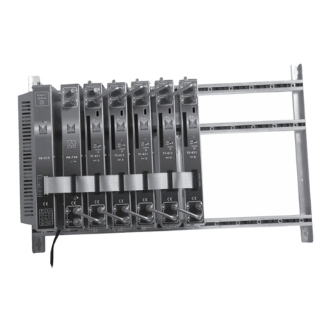
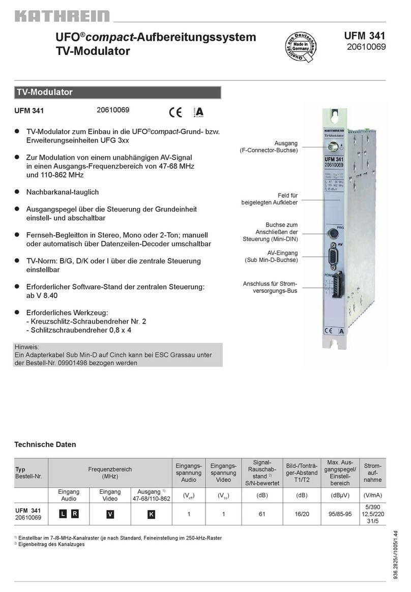
Hirschmann PAL 1 HU User manual

Manual
PAL modulator 1 HU
version: 1.2
print: March 96/BH_1760E
Hirschmann ü

Index
Introduction 1 - 1
General Notes. . . . . . . . . . . . . . . . . . . . . . . . . . . . . . . . . . . . . . . . . . . . . . . . . . . 1 - 2
Technical modifications . . . . . . . . . . . . . . . . . . . . . . . . . . . . . . . . . . . . . . . . . . . . . . . 1 - 2
Guarantee and Warranty . . . . . . . . . . . . . . . . . . . . . . . . . . . . . . . . . . . . . . . . . . . . . . 1 - 2
Copyright . . . . . . . . . . . . . . . . . . . . . . . . . . . . . . . . . . . . . . . . . . . . . . . . . . . . . . . . . . 1 - 2
Explanation of the warning and note symbols. . . . . . . . . . . . . . . . . . . 1 - 2
Operation 2 - 1
Functional description . . . . . . . . . . . . . . . . . . . . . . . . . . . . . . . . . . . . . . . . . . . 2 - 2
General. . . . . . . . . . . . . . . . . . . . . . . . . . . . . . . . . . . . . . . . . . . . . . . . . . . . . . . . . . . . 2 - 2
Block diagram. . . . . . . . . . . . . . . . . . . . . . . . . . . . . . . . . . . . . . . . . . . . . . . . . . . . . . . 2 - 3
Video processor VP 501/1 . . . . . . . . . . . . . . . . . . . . . . . . . . . . . . . . . . . . . . . . . . . . . 2 - 5
Vision/Sound modulator BTM 501/1 . . . . . . . . . . . . . . . . . . . . . . . . . . . . . . . . . . . . . 2 - 7
Sound2 modulator T2M 501/1 . . . . . . . . . . . . . . . . . . . . . . . . . . . . . . . . . . . . . . . . . . 2 - 9
IF matching unit . . . . . . . . . . . . . . . . . . . . . . . . . . . . . . . . . . . . . . . . . . . . . . . . . . . . 2 - 10
Interfaces. . . . . . . . . . . . . . . . . . . . . . . . . . . . . . . . . . . . . . . . . . . . . . . . . . . . . . . 2 - 11
Module frontside. . . . . . . . . . . . . . . . . . . . . . . . . . . . . . . . . . . . . . . . . . . . . . . . . . . . 2 - 11
Module rear side. . . . . . . . . . . . . . . . . . . . . . . . . . . . . . . . . . . . . . . . . . . . . . . . . . . . 2 - 12
Putting the modulator into operation. . . . . . . . . . . . . . . . . . . . . . . . . . . . 2 - 13
Help with problems . . . . . . . . . . . . . . . . . . . . . . . . . . . . . . . . . . . . . . . . . . . . . 2 - 14
Video processor . . . . . . . . . . . . . . . . . . . . . . . . . . . . . . . . . . . . . . . . . . . . . . . . . . . . 2 - 14
Vision/sound modulator . . . . . . . . . . . . . . . . . . . . . . . . . . . . . . . . . . . . . . . . . . . . . . 2 - 14
Sound2 modulator . . . . . . . . . . . . . . . . . . . . . . . . . . . . . . . . . . . . . . . . . . . . . . . . . . 2 - 15
Index
Manual
0 - 2 PAL modulator 1 HU ü

Service 3 - 1
Warning Note . . . . . . . . . . . . . . . . . . . . . . . . . . . . . . . . . . . . . . . . . . . . . . . . . . . 3 - 2
Adjustments. . . . . . . . . . . . . . . . . . . . . . . . . . . . . . . . . . . . . . . . . . . . . . . . . . . . . 3 - 2
Functional check. . . . . . . . . . . . . . . . . . . . . . . . . . . . . . . . . . . . . . . . . . . . . . . . 3 - 2
Handling . . . . . . . . . . . . . . . . . . . . . . . . . . . . . . . . . . . . . . . . . . . . . . . . . . . . . . . . 3 - 2
Equipment . . . . . . . . . . . . . . . . . . . . . . . . . . . . . . . . . . . . . . . . . . . . . . . . . . . . . . 3 - 3
Customer Service. . . . . . . . . . . . . . . . . . . . . . . . . . . . . . . . . . . . . . . . . . . . . . . 3 - 4
Data sheets 4 - 1
Data sheet index. . . . . . . . . . . . . . . . . . . . . . . . . . . . . . . . . . . . . . . . . . . . . . . . 4 - 2
Data sheet identification . . . . . . . . . . . . . . . . . . . . . . . . . . . . . . . . . . . . . . . . 4 - 2
Index
Manual
üPAL modulator 1 HU 0 - 3

Index
Manual
0 - 4 PAL modulator 1 HU ü

Introduction
Introduction
Manual
üPAL modulator 1 HU 1 - 1

General Notes
CAUTION: Keep the manual handy all the time.
Technical modifications
The information contained in this manual is subject to change at any time.
Guarantee and Warranty
The Hirschmann Company assumes no liability whatsoever (liability for material
defects, legal warranty, guarantee for marketability, violation of existing patent
rights) with the exception of the guarantees indicating in this manual.
Copyright
This manual covers information protected by copyright. All rights are reserved.
No part of this manual may be photocopied, otherwise reproduced or translated
into another language without the prior written consent of Hirschmann.
Explanation of the warning and note symbols
WARNING: Indicates that non compliance with the cautionary
measures listed could result in personal injury or
equipment damage.
CAUTION: Indicates that non compliance with the cautionary
measures listed could result in equipment damage.
NOTE: Comments giving useful tips and information on
practical application.
Introduction
Manual
1 - 2 PAL modulator 1 HU ü

Operation
Operation
Manual
üPAL modulator 1 HU 2 - 1

Functional description
General
The PAL modulator is used in headend systems. It processes a scrambled
video signal and supplies the following IF signals:
l
IF vision carrier
l
IF sound carrier 1 (IF SC1)
l
IF sound carrier 2 (IF SC2)
l
IF sound carrier 1+2 (IF SC1+2)
It can be used for stereo/2sound and mono transmission.
The PAL modulator functional group consists of:
l
Assy video processor
l
Assy vision/sound modulator
l
Assy sound2 modulator
l
IF matching unit
l
IF locking
l
AUX assy
l
Remote record interface
l
Rear panel assy
l
Data processor
Arrangement All of the terminals of the module are located on the back of the main frame.
The monitoring outputs and the interface for the Data processor (PC monito-
ring) are located in front of it. Adjustment elements for tuning are on the front
panel and inside the module. The IF matching unit and the power supply are at-
tached to the rear side of the main frame.
Monitoring Check of the most important parameters can be made via the PC monitoring
software. Therefor a Dataprocessor DP 501-1 is nessesary, witch handle the
data communication between the PAL modulator and the PC.
The following signals are available on the rear side of the main frame on
connector "STATUS"
l
video signal on the video main sync. input is present
l
summary fault
Operation
Manual
2 - 2 PAL modulator 1 HU ü

Block diagram
Block diagram of overall PAL modulator 1 HU
Operation
Manual
üPAL modulator 1 HU 2 - 3

Schematic diagram of the video processor, vision sound modulator and sound2
modulator
Operation
Manual
2 - 4 PAL modulator 1 HU ü

Video processor VP 501/1
The video signal being fed in, it is precorrected in the video processor and fed
the vision/sound modulator.
Inputs The video processor has the following inputs:
l
VIDEO MAIN IN: Scrambled main video input
l
VIDEO AUX IN: Substitute video input
l
VIDEO MAIN SYNC IN: Video signal with standard sync pulse
Arrangement The video processor consists of a main assembly which holds the AUX assem-
bly (substitute signal processing). The EPROM for text field insertion is located
on the AUX assembly.
Input part The video main input can be switched from symmetric to asymmetric.
Input signal present LED "VIDEO" lights up, when the input signal (VIDEO MAIN SYNC IN) is pre-
sent. The information whether the input signal is present is also available on
the rear side of the main frame (Connector "STATUS").
Control The input level can be adjusted in a range from -3 ... +3 dB using the front
panel potentiometer "VIDEO IN".
Switch-over main/sub-
stitute signal Switch-over to the substitute signal can be done in two ways:
l
Automatic switch-over
l
Forced switchthrough
The video processor reports to the vision/sound modulator via the control line
"MAIN/AUX", indicating whether the main or the substitute signal is connected,
so the sound can be simultaneously switched to the substitute signal.
Automatic switch-over The switch-over to the substitute signal is automatic if the video signal (VIDEO
MAIN SYNC IN) has no standard sync pulses.
Forced switchthrough The switchover to the substitute signal can also be performed by the monito-
ring software (known as "forced switchover"). The automatic switchover is then
blocked and the following LED lights up
l
REMOTE MAIN in the event of a forced switchover to the
operating signal
l
REMOTE AUX in the event of a forced switchover to the
substitute signal
Text insertion The customer specified text, inserted in the substitute picture, is stored in an
EPROM. The text field insertion feature can be switched off with the monitoring
software. The EPROM for the text insertion is not fitted in the video processor
VP 501/1 but can easily be installed any time.
Operation
Manual
üPAL modulator 1 HU 2 - 5

Monitoring output The level of the monitoring output is the same, whether the group delay precor-
rection is bridged or not.
Control The following controls can be carried out with the monitoring software:
l
forced switchthrough of main/substitute signal
l
switch on/off of text insertion
Block diagram
Video processor
Operation
Manual
2 - 6 PAL modulator 1 HU ü

Vision/Sound modulator BTM 501/1
Within the vision/sound modulator, the vision carrier (38,9 MHz) is amplitude-
modulated by the processed video signal and VSB-filtered. The audio proces-
sing, the matrixing and the modulation of the 1st sound carrier also takes place
in the vision/sound modulator. The vision sound modulator supplies the
l
IF vision carrier and
l
IF sound carrier 1.
Quarz oscillator The oscillator in the vision sound modulator is locked to the external reference
frequency (REF).
SAW filter Following the VSB modulation, the saw filter limits the band width, ensuring
flawless adjacent channel operation.
Sound part The sound part contains two symmetric audio inputs with switchable input impe-
dance (600 ohm/>12 kohm).
The level can be set between 0/+6 dBm (referenced to 600 ohm) using swit-
ches on the assembly and in a range from -3 ... +3 dB on the front panel.
The substitute sound inputs are asymmetric, highly resistive and not tunable.
(Level = +6 dBm / 600 Ohm)
Preemphasis The preemphasis (50 µs) can be switched off on the assembly to carry out
measurements.
Matrixing The transmission mode (mono/stereo/2sound) is determined from the data line
in the sound2 modulator. This information is then passed to the
vision/sound modulator via the "stereo" control line.
Sound IF The sound carrier frequencies 33,4 and 33,158 MHz are derived from the
vision carrier frequency 38,9 MHz and are frequency-modulated directly by the
matrixed audio signals.
Sound carrier lowering The sound carrier can be lowered by 3 dB with a switch on the assembly.
Switchover to
the substitute signal The switchover to the substitute signal occurs at the same time with the video
processor. The timing of the switchover is determined in the video processor
and this information is passed on to the vision/sound modulator via the
"MAIN/AUX" control line.
Operation
Manual
üPAL modulator 1 HU 2 - 7

Block diagram
Vision/sound modulator
Operation
Manual
2 - 8 PAL modulator 1 HU ü

Sound2 modulator T2M 501/1
In the sound2 modulator the second sound carrier (33,158 MHz) is frequency-
modulated by the matrixed audio signal 2 and the pilot signal. The sound2 mo-
dulator generates the identification frequency the pilot is modulated with.
Carrier frequency The carrier frequency is derived from the vision carrier, for which purpose the
vision/sound modulator makes available the reference signal "REF-SND2".
Sound carrier lowering The modulated IF carrier 2 can be lowered by 3 dB with a switch on the assem-
bly and then is passed to the vision/sound modulator.
Transmission mode The transmission mode (mono/stereo/2sound) is determined from the data line
of the video signal (on VIDEO MAIN SYNC IN) with a data line decoder.
The LED "DATA LINE" lights up, if the data line is present.
The transmission mode can also be determined with the monitoring software or
on the connector "SOUND MAIN IN". If it is, the LED "REMOTE" lights up.
The transmission mode is shown by LEDs on the front panel.
The following list indicates the priority ranking of the controls:
l
1. Control with the monitoring software.
l
2. Hardware control via the rear panel assembly (MODE).
l
3. Data line analysis.
l
4. If no data line is detected, modulator switches automatically to 2sound
operation.
Pilot The pilot and the identification frequency are locked to the line frequency (on
VIDEO MAIN SYNC IN). The pilot is modulated at a different frequency
depending on the transmission mode.
l
MONO unmodulated (0 Hz)
l
STEREO 117,5 Hz
l
2SOUND 274,1 Hz
The pilot can be switched off (on the assembly) to carry out measurements.
Controls The following controls can be carried out by the monitoring software:
l
Sound 2 (S2OFF): Switches the output off
l
Sound State: Determines the transmission mode mono/stereo/2sound
Operation
Manual
üPAL modulator 1 HU 2 - 9

Block diagram
IF matching unit
General The IF matching unit generates of the sound carrier 1 and 2 the following si-
gnals:
l
IF SND1 OUT
l
IF SND 2 OUT
l
IF SND 1+2 OUT
The IF matching unit is made up of impedance transforming from 50 to 75 ohm.
Block diagram
Sound2 modulator
IFSND1OUT
IFSND1+2 OUT
IF SND 2 OUT
IF SC 1
IF SC 2
75
50
50 MHz
50 MHz 75
50
75
50
block diagram IF matching unit
Operation
Manual
2 - 10 PAL modulator 1 HU ü

Interfaces
Module frontside
1 ... Lights up in the event of a module fault (red) - see data sheet 1763
2 ... Lights up, when a standard equivalent video signal is fed in at the
video main sync input (green)
3 ... Lights up, when the operating signal is switched through via the remote
control (yellow)
4 ... Lights up, when the substitute signal is switched through via the remote
control (yellow)
5 ... Setting of the video level (+/- 3 dB)
6 ... Monitoring output for the video signal
7 ... Lights red at module fault,see data sheet 1765
8 ... Potentiometer for the adjustment of the freq. deviation of sound1 (+/- 3 dB)
9 ... Potentiometer for the adjustment of the freq. deviation of sound2 (+/- 3 dB)
10 ... IF monitoring output
11 ... Monitoring output for audio signals 1/2
12 ... Lights at module fault (red), see data sheet 1766
13 ... Lights, when data line is present (green)
14 ... Lights, when the operation mode has been fixed over the remote
controll (PC) or over the control line (MODE) (yellow)
15 ... Lights at MONO operation (yellow)
16 ... Lights at STEREO operation (yellow)
17 ... Lights at 2-SOUND operation (yellow)
18 ... Interface for a data processor
Operation
Manual
üPAL modulator 1 HU 2 - 11

Module rear side
1 ... Fuse box (2 x 0.63 AT)
2 ... mains supply
3 ... Status output (STATUS)
4 ... IF sound carrier 1+2 output (IF SND1+2 OUT)
5 ... IF sound carrier 2 output (IF SND2 OUT)
6 ... IF sound carrier 1 output (IF SND1 OUT)
7 ... IF vision carrier output (IF VIDEO OUT)
8 ... IF reference frequency input (IF REF. IN)
9 ... Video auxilliary input (VIDEO AUX. IN)
10 ... Unscrambled video input (VIDEO MAIN SYNC. IN)
11 ... Scrambled video input (VIDEO MAIN IN)
12 ... Audio auxilliary input (SOUND AUX. IN)
13 ... Audio input (SOUND MAIN IN)
Note: For pin assignments see data sheet 1760
Operation
Manual
2 - 12 PAL modulator 1 HU ü

Putting the modulator into operation
Requirements The modules should be correctly set. If they are not, read the instruction in the
data sheet.
NOTE: If at all possible, use the PC monitoring software or an
oscilloscope for putting the modulator into operation.
CAUTION: If the main frame is steamed up after unpacking, allow it to
become acclimated for at least one hour before putting the
modulator into operation !
1. Feed in the video main signal (1 Vpp, Black porch 0 V), video main sync si-
gnal (1 Vpp), audio and reference signals.
2. Feed in the main voltage
3. Check to make sure no red LED lights up.
4. Check to make sure the green LED "VIDEO" lights up.
Putting the video proces-
sor into operation 1. Turn the front panel potentiometer "VIDEO IN" until 700 mV white level is
displayed by the PC monitoring software.
If you put the video processor into operation without the PC monitoring soft-
ware, connect an oscilloscope to the monitoring output "VIDEO MON.". Set
the amplitude of white value to 0,7 V.
Putting the vision/sound
modulator into operation 1. Set the deviation for a live signal with the potentiometer "SOUND DEVIATI-
ON" to a maximum of 30 kHz (30 kHz deviation corresponds to 1.55 Veff at
the monitoring output). Use the monitoring sotware or connect a suitable
measuring instrument to the audio monitoring output "AF MON.".
Putting the sound2 modu-
lator into operation 1. Check to make sure the corresponding yellow LEDs lights up.
2. If you control the transmission mode (mono/stereo/2sound) by hardware, set
the pins at the connector "SOUND MAIN IN" in accordance with the table
"Transmission mode" - see data sheet 1760.
Operation
Manual
üPAL modulator 1 HU 2 - 13

Help with problems
Video processor
Symptom Remedy
Red LED on Error in module video
- Check the fuse on the assembly (see data sheet 1760)
Green LED "VIDEO" off - No standard sync pulse on the video main sync input
- Check the connections on the rear panel of module
No text insertion in the
substitute signal
although the EPROM
is fitted
- Check the input signal at the monitoring output
- Check the settings on the PC
Video processor fails to
switch to the substitute
signal if the input si-
gnal is not present,
REMOTE LED on
Forced switch-through of the main input
- Check the settings on the PC
No output signal,
red LED off
LED "VIDEO" on,
LED "REM AUX" off
Signal path in video processor is interrupted
- Check the switch settings in the module (see Data sheet)
No LED’s are on No operating voltage is being supplied to the module
- Check the operating voltage supply on the rear panel
- Check the fuse on the assembly (see data sheet 1760)
Vision/sound modulator
Symptom Remedy
Red LED on Error in module
- Check the fuse on the assembly (see data sheet 1760)
PLL unlocked from sound1 or no vision IF or no sound1 IF
- Check the settings on the PC
Vision carrier is not modulated even though a video signal
complying with the standard is applied at the video main
sync. input
- Check the connections on the rear panel of module
Red LED lights up and
green LED "VIDEO" is
on
Video main sync. signal is present but no video main signal. -
- Check the connections on the rear panel of module.
Operation
Manual
2 - 14 PAL modulator 1 HU ü
Table of contents
