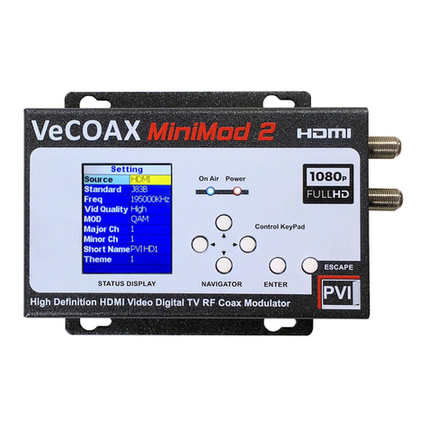
Toner TAMM-QAM User manual

User’s Manual
Mini Modular Type HD
Modulator
8VSB/QAM
Model No : TAMM-QAM
969 Horsham Road Horsham, Pennsylvania 19044 USA Phone: 215-675-2053 Fax: 215-675-7543 [email protected]

Contents
1. Safety Instructions & Precautions
2. Operation Guide
2-1. Connection Diagram
2-2. Front Plate
2-3. Rear Panel
2-4. Functions of Operating Button

3. System Configurations
3-1. Configure through web
3-1-1. Ethernet
3-1-2. Audio & Video
3-1-3. QAM
3-1-4. RF
3-1-5. Ts Stream
3-1-6. Misc
3-1-7. Save
3-1-8. Copy
3-1-9. Restore
3-1-10. Preset Values
4. IP Network Connection thru RJ45
4-1. Using factory’s IP address/domain
4-2. Using non factory’s IP address/domain or Router
4-2-1. Connection - PC<==>Modulator
4-2-2. Connection - PC<==>Router<==>Modulator

1
1. Safety Instructions & Precautions
Do not operate the Unit in high-humidity areas, or expose it to water ormoisture.
No objects filled with liquid should be placed on the device.
Disconnect the unit from the wall outlet prior tocleaning. Use alight, damp cloth
(no solvents) to dustor clean the product.
Do notblock orcover slots and openings inthe Unit. These are provided for
ventilation and protection from overheating. Never place the Unit near orover a
radiator orheat register. Donotplace the Unit in an enclosure such as a cabinet
without proper ventilation.
We strongly recommend using the enclosed ground wire connecting tothe ground
cable ofyour house/building toavoid voltage spikes orground fault.
Never insert objects of any kind into the Unit through openings, asthe objects may
touch dangerous voltage points orshort out parts. This also could cause fire or
electrical shock.
For using Mini Modular System’s Products, space under and above Mini modular
chassis is always necessary.
There are no user serviceable parts in this device. Repairs should only be made by
qualified and factory authorized service providers or by the factory itself. Failing to
follow these guidelines may void the warranty and could cause unsafe conditions.
!
CAUTION
RISK OF ELECTRIC SHOCK
DO NOT OPEN
The lightning flash with arrow-
head symbol within an equilateral
triangle is intended to alert you
to the presence of uninsulated
“dangerous voltage” within the
product’s enclosure that may be
of sufficient magnitude to consti-
tute a risk of electrical shock to
persons.
The exclamation point within an
equilateral triangle is intended
to alert you to the presence of
important operating and main-
tenance (servicing) instructions
in the literature accompanying
the product.
TO REDUCE THE RISK OF ELECTRICAL SHOCK, DO NOT REMOVE COVER FROM THIS UNIT.
NO USER-SERVICEABLE PARTS INSIDE. REFER SERVICING TO QUALIFIED SERVICE PERSONNEL.

1
Instructions
The TAMM-QAM is an agile encoder/modulator designed for use in TV signal
distribution. It will encode and modulate an HDMI signal in MPEG2 in SD or HD and
output a QAM channel or an 8VSB channel.
Insert the TAMM-QAM in an appropriate rack chassis such as the TMMRC-12 or
similar. When inserting the modulator card, edges are designed to fit in the slide slots
in the chassis. Once the modulator is installed, plug in the wiring harness to the
mating plug on the rear of the modulator. NOTE the plug can only be inserted one
way, do not force it and reversing the electrical connection will cause damage.
Once the modulator is installed, connect the HDMI cable and the RF output connector
as needed to the system.
On the front of the TAMM-QAM, you will find one RJ45 connector to connect the
modulator to a computer for setup. The default IP address is 192.168.1.149.

2
2. Operation Guide
2-1. Connection Diagram
A. Connect the power supply.
B. Connect the HDMI source to this product.
HDMI can reach HD resolution 1080p.
C. Connect the RF Output to the RF network, STB or the TV set directly.
* According to your headend system, set the output power attenuation on this product properly.
D. For safety purpose, use the ground wire enclosed with the modulator to connect to your
ground cable.

3
2-2. Front Plate
1. Power LED Indicator
2. RJ45 : for Remote Setting

4
2-3. Rear Panel
1. Channel Up / Down
2. HDMI : Digital A/V Input
3. DC 5V/12V IN:5V/12VDC power supply input
4. RF OUT:F type connector for RF output
** Important notes for HDMI input ** :
When HDMI signal is off-and-on or re-plug, or changing the video resolution, the unit will auto detect
video signal.
During the time of auto detection video pictures would freeze or black. However video pictures
continuously display again in 15 seconds or so.
Most other brand units in the market would need to re-boost the unit once HDMI signal is off-and-on
or re-plug, or changing the video resolution.

5
2-4. Functions of Operating Button
Please see following instructions of buttons on the rear panel to operate in each setting category.
“CH+” / “CH-” :
1. For channel change.
2. For Software Update :
Step 1. Keep depressing both Channel
Up/Down key buttons
Step 2. Power on the modulator
Step 3. Now follow up software update
procedures
3. For IP Default :
Step 1. The modulator is on after powering.
Step 2. Keep depressing both Channel
Up/Down key buttons for 3 seconds
Step 3. Now IP address is factory default.
3. System Configurations
Configuration can be processed through web.
3-1. Configure through web
Set an IP address of the modulator from the front panel if you don’t want to use the default IP
address. Connect the modulator to the computer through RJ45 cable.
Enter the IP address of the modulator (Default address: 192.168.1.149) on web browser
Press <Update> after changing settings in each category. Go to SAVE page to save the
configurations.

6
3-1-1. Ethernet– For Web Configuration
All the values are locked. Uncheck <Enable/Disable Editing> to edit.

7
3-1-2. Audio & Video- Audio & Video Input Configuration
Video BitRate range : 5000~20000 kb/s

8
3-1-3. QAM - constellation setup

9
3-1-4. RF - RF Output Configuration
Channel Mode
Remain “CW Signal” in “Disable”. This option is only for testing purpose in factory.
The modulator can’t work if enable this function.

10
3-1-5. Ts Stream– stream editing
The value of Video PID /Audio PID /PCR PID/ PMT PID should be unique to each
other.

11
3-1-6. Misc– For system configuration
Options of Factory default setting (Preset):
B-64 (Annex B, 64QAM) / B-256 (Annex B, 256QAM) / 8VSB

12
3-1-7. Save – To save changes of configuration

13
3-1-8. Copy – To copy your exiting data, please take the following steps :
1. Go to “Save” tab in browser.
2. Click “Backup / Restore”.
3. Click “Download backup Database” button. Setting will be exported into a configuration
file.
3-1-9. Restore – To restore your saved data, please take the following steps :
1. Go to “Save” tab in browser.
2. Click “Backup / Restore”.

14
3. Click “Choose File” to select the configuration file.
4. Click “Restore Database”.
3-1-10. Preset Values
The following table shows only differences between presets. Items not shown in the table
are the same as default.
8VSB
B-64 (Default)
Frequency plan : NTSC-AIR
Frequency plan : NTSC-CATV
Modulation mode : 8VSB
Modulation mode : QAM_B_64
B-256
Frequency plan : NTSC-CATV
Modulation mode : QAM_B_256
4. IP Network Connection thru RJ45
4-1. Using factory’s IP address/domain
Please refer to IP address labeled on the modulator.
4-2. Using non factory’s IP address/domain or Router
4-2-1. Connection - PC<==>Modulator
Example: Change IP 192.168.1.242 to 192.168.2.42

15

16
4-2-2. Connection - PC<==>Router<==>Modulator
Example: Gateway:192.168.2.xxx
*Your Router and Network Domain are used (such as 192.168.2.0 or 192.168.100.0).
*Gateway address is always Router IP address such as 192.168.2.254.
Table of contents
Other Toner Modulator manuals
