Hirschmann iFLEX TRS 14 User manual

iFLEX TRS 14
Transceiver
for wireless sensors Contents
Safety instructions 1
Product description 2
Installation 3
Commissioning 4
Configuration 5
Service and maintenance 6
Technical data 7
User manual
Issue A - 08/2010
This document has the order no.
21-810-19-0003_421830_en

TABLE OF CONTENTS
1Safety instructions...........................................................................................6
1.1 EU conformity declaration ............................................................................8
2Product description .......................................................................................10
2.1 General .......................................................................................................10
2.2 Product features .........................................................................................11
2.3 Use for the intended purpose .....................................................................11
2.4 Scope of supply ..........................................................................................11
2.5 View of device.............................................................................................12
2.6 Dimensions .................................................................................................13
3Installation.......................................................................................................14
3.1 Mounting the components ..........................................................................14
3.1.1 iFLEX TRS 14 ....................................................................................14
3.1.2 Magnetic base antenna......................................................................14
3.2 Electrical connection...................................................................................15
3.2.1 Wiring of the central connector ..........................................................16
3.2.2 Wiring of the connecting cable...........................................................16
4Commissioning...............................................................................................17
4.1 Switching the device on..............................................................................17
4.2 Status LEDs................................................................................................19
4.3 Opening/closing the housing ......................................................................20
4.4 Preconfiguration of the output signals (current/voltage).............................22
5Configuration..................................................................................................23
5.1 Overview of functions .................................................................................24
5.2 Registering a wireless sensor.....................................................................25
5.3 Deleting wireless sensors...........................................................................27
5.4 Setting the signal range..............................................................................28
5.5 Adjusting the zero point (load/angle sensor only) ......................................30
5.6 Erasing the EEPROM.................................................................................31
5.7 Setting the angle range (angle sensor only)...............................................32
6Service and maintenance..............................................................................33
7Technical data.................................................................................................34
© 2010 Hirschmann Automation and Control GmbH · Branch Office Ettlingen · E-mail: info.ecs@hirschmann.de 2/37
21-810-19-0003_421830_en (Rev A).doc / 2010-08-31 / Issue A / rk.

Tables and illustrations
Table 1 Overview of wireless sensors ................................................................. 10
Table 2 Overview of status LED .......................................................................... 19
Table 3 Overview of signal ranges ...................................................................... 28
Figure 1: View of the iFLEX TRS 14.................................................................... 12
Figure 2: Dimensions of the iFLEX TRS 14 (with magnetic base antenna) ........ 13
Figure 3: Magnetic base antenna (art. no.536023) with mounted radiator.......... 14
Figure 4: Pin configuration of the central connector ............................................ 16
Figure 5: Wiring of the connecting cable ............................................................. 16
Figure 6: View of the programming button .......................................................... 23
VERSION OVERVIEW
Issue Date Description Editor
A 2010-08-31 First issue, translation of the german original issue A Konopka
HIRSCHMANN Automation and Control GmbH
Hertzstr. 32-34, 76275 Ettlingen, phone +49 (0)7243-709-0
© 2010 Hirschmann Automation and Control GmbH · Branch Office Ettlingen · E-mail: info.ecs@hirschmann.de 3/37
21-810-19-0003_421830_en (Rev A).doc / 2010-08-31 / Issue A / rk.

Introduction
INTRODUCTION
This manual is a component of the equipment or system supplied by Hirschmann Automation and
Control GmbH. Keep this manual in a safe place and ensure that it is available to all users.
About this manual
The contents of this manual are subject to change. Hirschmann Automation and Control GmbH
does not provide any guarantee for this material, including the associated guarantee regarding
marketability and suitability for certain intended purposes. Hirschmann Automation and Control
GmbH accepts no liability for errors in the contents of the manual or for direct or indirect damage in
connection with the provision and use of the manual.
Liability disclaimer
This manual is protected by copyright. All rights reserved. The manual may not be duplicated, re-
produced or translated into another language, either wholly or partly, without the prior written per-
mission of Hirschmann Automation and Control GmbH.
Copyright
notice
The rendition of common names, trade names, trademarks etc. in this documentation should not be
construed to mean that such names, even without special identification, are free in the sense of
trademark and trademark protection legislation and hence usable by anyone.
Trademarks
This device / system is intended exclusively for the tasks described in this manual. Any other use
shall be construed as being inappropriate. The manufacturer accepts no liability for damage caused
by inappropriate or impermissible use. This device / system may only be used if it is in perfect tech-
nical condition.
Use for the intended
purpose
Only appropriately qualified personnel may work with this device / system, i.e. persons:
Qualification of the
operating personnel who are familiar with the operation or installation and commissioning
who know the current regulations for the prevention of accidents
© 2010 Hirschmann Automation and Control GmbH · Branch Office Ettlingen · E-mail: info.ecs@hirschmann.de 4/37
21-810-19-0003_421830_en (Rev A).doc / 2010-08-31 / Issue A / rk.

Introduction
Marking of notices
Dangers and other important notices are marked as follows in this user manual:
WARNING
Warning of direct threat of personal injury and damage to property.
Instructions on precautions to avert the danger.
CAUTION
Warning of dangerous situations. Also warns of damage to property.
Instructions for averting the danger.
IMPORTANT
Warning of possibly damaging situation for the product.
Instructions for avoiding the possibly damaging situation.
NOTE
Usage instructions and information, but no dangerous situation.
HINT
Supplementary comments and recommendations for the user.
© 2010 Hirschmann Automation and Control GmbH · Branch Office Ettlingen · E-mail: info.ecs@hirschmann.de 5/37
21-810-19-0003_421830_en (Rev A).doc / 2010-08-31 / Issue A / rk.

Safety instructions
1 Safety instructions
In order to avoid possible personal injuries and damage to property when using this device, it is
essential to observe the following safety instructions:
CAUTION
Danger of electrical short-circuits.
Switch off all systems before commencing with the installation work!
CAUTION
Danger due to the inadvertent registration of a nearby wireless sensor.
Make sure that the batteries of other wireless sensors are not changed during a registration
procedure on an iFLEX TRS 14.
IMPORTANT
Damage to the device if connected to an unsuitable power supply.
The device may only be connected to a DC voltage source of 10 V to 30 V!
IMPORTANT
Damage to the equipment due to non-compliance with the regulations for the handling of
equipment containing electrostatically sensitive devices (ESDs):
Pay attention to the following instructions if the device has to be opened during commis-
sioning:
• Discharge yourself (e.g. by touching an earthed object) before opening the device
• Hold the printed circuit board only by the edges
• Do not touch components or connector pins or tracks
© 2010 Hirschmann Automation and Control GmbH · Branch Office Ettlingen · E-mail: info.ecs@hirschmann.de 6/37
21-810-19-0003_421830_en (Rev A).doc / 2010-08-31 / Issue A / rk.
Safety instructions
IMPORTANT
Impairment of the system function due to the use of an unsuitable antenna radiator.
Always use the antenna radiator included in the scope of supply!
IMPORTANT
Impairment of the system function or breaching of radio transmission regulations by the use
of components or extensions not approved by the manufacturer.
Use exclusively components or extensions that are intended and approved by the manufac-
turer.
IMPORTANT
Possible impairment of the radio link/range in direct proximity to antenna systems with a
high HF transmission power.
The device must not be used in the direct proximity of radar systems or transmitters (e.g.
radio, TV, mobile telephone etc.) or close to power supply systems.
IMPORTANT
Damage to the device due to the penetration of water and dirt.
Never clean the device with a high pressure cleaner!
Have damage to the decorative foil repaired professionally without delay!
© 2010 Hirschmann Automation and Control GmbH · Branch Office Ettlingen · E-mail: info.ecs@hirschmann.de 7/37
21-810-19-0003_421830_en (Rev A).doc / 2010-08-31 / Issue A / rk.
Safety instructions
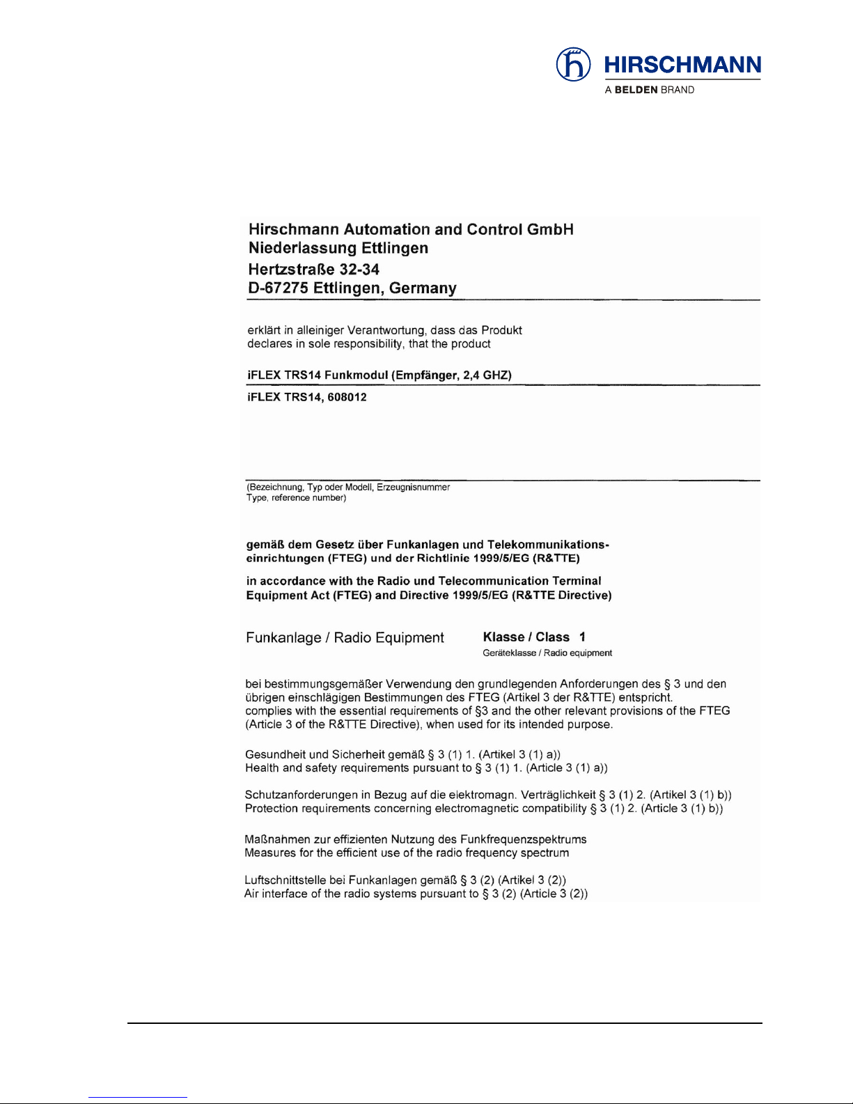
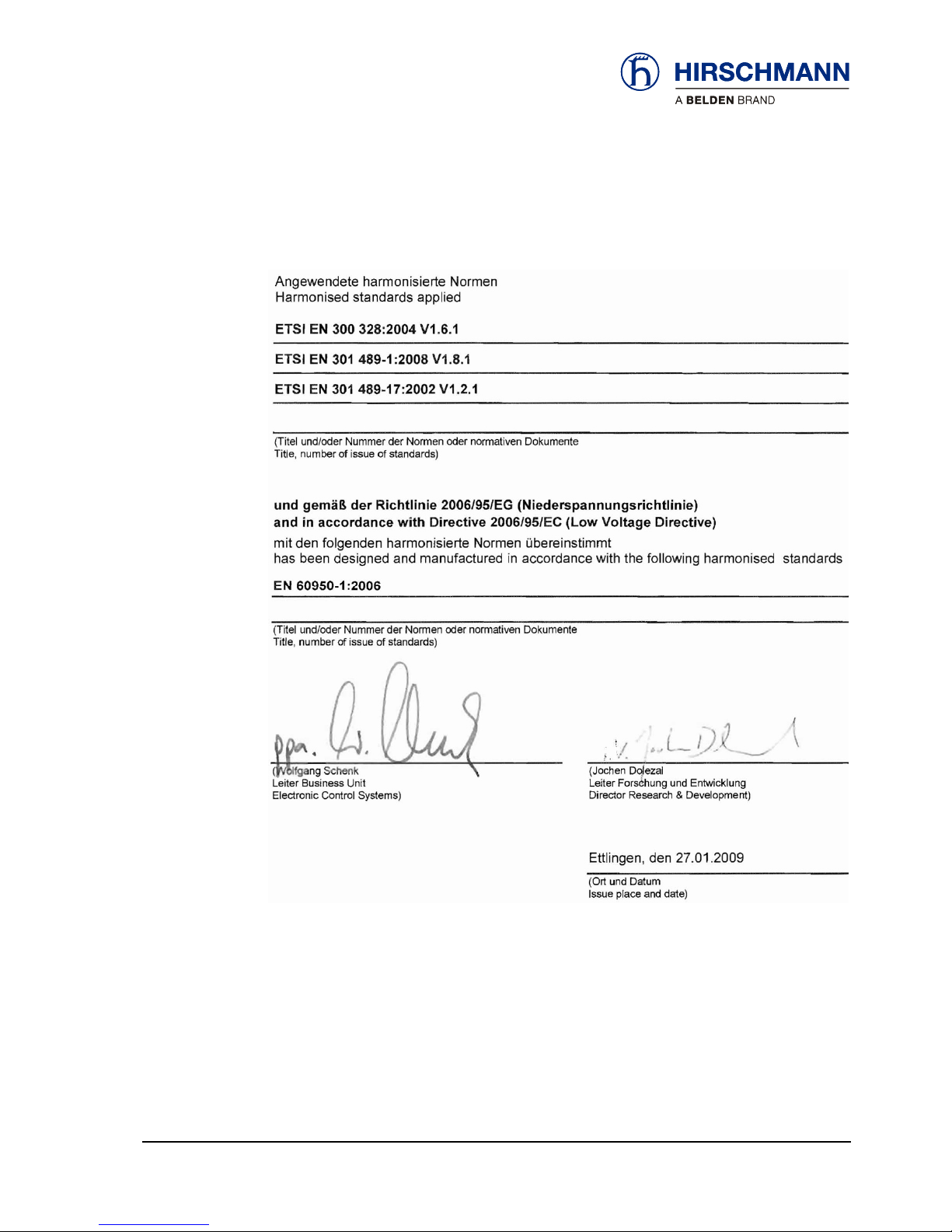
1.1 EU conformity declaration
© 2010 Hirschmann Automation and Control GmbH · Branch Office Ettlingen · E-mail: info.ecs@hirschmann.de 8/37
21-810-19-0003_421830_en (Rev A).doc / 2010-08-31 / Issue A / rk.
Safety instructions
© 2010 Hirschmann Automation and Control GmbH · Branch Office Ettlingen · E-mail: info.ecs@hirschmann.de 9/37
21-810-19-0003_421830_en (Rev A).doc / 2010-08-31 / Issue A / rk.

Product description
2 Product description
2.1 General
The iFLEX TRS 14 is a transceiver for the wireless coupling of wireless sensors from the Hirsch-
mann xSENS-xxx-W1 family.
Up to 4 wireless sensors can be connected wirelessly to a single iFLEX TRS 14. The number of
wireless sensors can be extended as required by the employment of several transceivers.
How many sensors
can be connected?
All sensors from the xSENS-xxx-W1 family from Hirschmann’s extensive range of wireless sensors
can be used.
(the article numbers given on the right refer in each case to the sensors including accessories)
Application Product designation
Which wireless sen-
sors can be used?
Article no.
(set)
Load
measurement
fSENS KMD-006-W1 (up to 6 t)
Art. no. 605792
alternatively also
fSENS KMD-020-W1 (up to 20 t)
Art. no. 606345
Angle
measurement
gSENS WGF-W1 (0 to 90°)
Art. no. 608016
e.g. for boom angle measurement
or
gSENS WGS-W1 (-15 to +15°)
Art. no. 608185
for inclination measurement
Wind
measurement
iSENS WSS-W1
608179
Hoist limit
monitoring
(A2B)
iSENS HES-W1
Art. no. 608015
608180
Table 1 Overview of wireless sensors
© 2010 Hirschmann Automation and Control GmbH · Branch Office Ettlingen · E-mail: info.ecs@hirschmann.de 10/37
21-810-19-0003_421830_en (Rev A).doc / 2010-08-31 / Issue A / rk.

Product description
2.2 Product features
The iFLEX TRS 14 is characterised by the following features:
Wireless coupling of up to four wireless sensors from the xSENS-xxx-W1 family
Registration of a wireless sensor to the receiver at the push of a button
Relay output for hoist limit signal
Four analog signal outputs (configurable for current/voltage)
Status LEDs for signalling various operating conditions
Monitoring of the battery condition of the connected wireless sensors
Self-diagnostic function
Sensor calibration by radio command
Protection class IP65, hence also suitable for outdoor use
Operating temperature -40 to +85 °C
Voltage supply 10 to 30 V DC
2.3 Use for the intended purpose
The iFLEX TRS 14 is a transceiver for the transmission of sensor data collected wirelessly from up
to four radio sensors from the xSENS-xxx-W1 family.
Configurable signal outputs make universal adaptation possible. Because of possible impairment of
radio communication/range in direct proximity to antenna systems with a high HF transmission
power, the device must not be used in the direct proximity of radar systems or transmitters (e.g.
radio, TV, mobile telephone etc.) or close to power supply systems.
2.4 Scope of supply
The scope of supply of the iFLEX TRS 14 with accessories (art. no. 608177) consists of the follow-
ing parts:
iFLEX TRS 14
Magnetic base antenna with 4 m connecting cable
Antenna radiator
Connecting cable, 4,7 m, with prefabricated central plug at one end
User manual on CD
© 2010 Hirschmann Automation and Control GmbH · Branch Office Ettlingen · E-mail: info.ecs@hirschmann.de 11/37
21-810-19-0003_421830_en (Rev A).doc / 2010-08-31 / Issue A / rk.
Product description
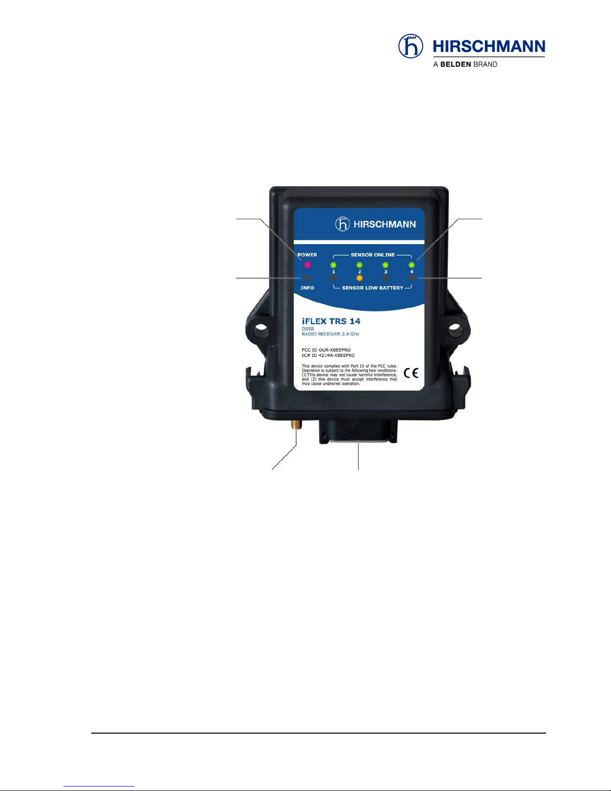
2.5 View of device
Operating
status
Indicators for
registered wire-
less sensors
channels 1 to 4
Indicator fo
r
hoist limit
signal
Indicator for
weak sensor
battery
channels 1 to 4
Coaxial socket
for antenna
Central plug
Figure 1: View of the iFLEX TRS 14
© 2010 Hirschmann Automation and Control GmbH · Branch Office Ettlingen · E-mail: info.ecs@hirschmann.de 12/37
21-810-19-0003_421830_en (Rev A).doc / 2010-08-31 / Issue A / rk.
Product description
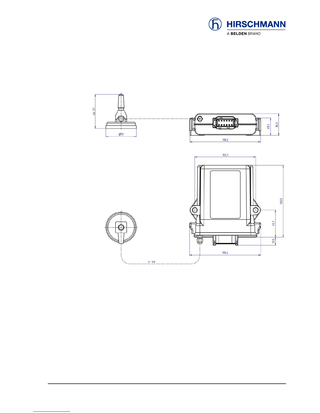
2.6 Dimensions
Figure 2: Dimensions of the iFLEX TRS 14 (with magnetic base antenna)
© 2010 Hirschmann Automation and Control GmbH · Branch Office Ettlingen · E-mail: info.ecs@hirschmann.de 13/37
21-810-19-0003_421830_en (Rev A).doc / 2010-08-31 / Issue A / rk.

Installation
3 Installation
3.1 Mounting the components
The iFLEX TRS 14 is supplied complete with all accessories required for operation. Mounting can
therefore be performed simply and quickly. For mounting the wireless sensors, please refer to the
instructions provided with the respective sensor.
3.1.1 iFLEX TRS 14
The iFLEX TRS 14 must be mounted in a suitable place on a sufficiently firm surface with the con-
nections at the bottom. The device may be used both indoors and outdoors and is to be mounted
such that the LEDs are visible.
The distance between the holes in the housing is 102 mm.
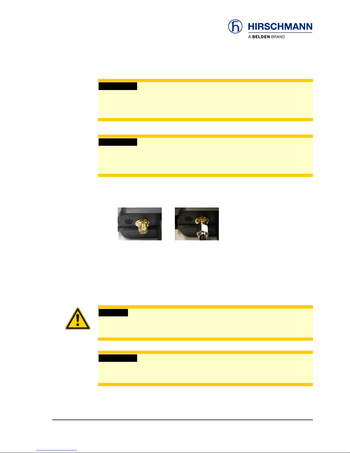
3.1.2 Magnetic base antenna
Antenna radiator 2.4 GHz
Antenna base
Magnetic baseplate
Figure 3: Magnetic base antenna (art. no. 536023) with mounted radiator
First of all, screw the antenna radiator hand tight onto the thread on the top side of the antenna
base until you feel a stop. (Remove the protective cap from the thread if necessary).
Preparation of the
antenna
The antenna has a magnetic baseplate and adheres securely to all ferromagnetic surfaces thanks
to its strong magnet.
How do I mount the
antenna?
NOTE
Optimal ranges are achieved if the antenna is aligned in accordance with the alignment of
the wireless sensor antennas and can radiate as freely as possible.
Niches or recesses are therefore less suitable as mounting locations!
© 2010 Hirschmann Automation and Control GmbH · Branch Office Ettlingen · E-mail: info.ecs@hirschmann.de 14/37
21-810-19-0003_421830_en (Rev A).doc / 2010-08-31 / Issue A / rk.
Installation
Please follow the instructions below for laying the antenna cable:
How should the
cable be laid? IMPORTANT
The antenna cable can be damaged if it is squeezed or kinked.
Therefore, lay the antenna cable in such a way that it is neither squeezed nor laid around
sharp edges!
IMPORTANT
The function of the antenna and hence the whole system can be impaired if a mismatching
antenna radiator is used.
Always use the antenna radiator contained in the scope of supply!
After laying the cable, connect the coaxial connector of the antenna to the antenna socket on the
underside of the iFLEX TRS 14. Screw the connector on hand tight.
Where is the an-
tenna
connected?
3.2 Electrical connection
Connection of the device is simple thanks to the connecting cable (4,7 m), which is prefabricated at
one end and included in the scope of supply. The open cable end is to be connected properly using
wire end ferrules. Please refer to the following illustrations for the wiring of the connecting cable and
the pin configuration of the central plug.
CAUTION
Danger of electrical short-circuits.
Switch off all systems before commencing with the installation work!
IMPORTANT
Damage to the device if connected to an unsuitable power supply.
The device may only be connected to a DC voltage source of 10 V to 30 V!
© 2010 Hirschmann Automation and Control GmbH · Branch Office Ettlingen · E-mail: info.ecs@hirschmann.de 15/37
21-810-19-0003_421830_en (Rev A).doc / 2010-08-31 / Issue A / rk.

Installation
3.2.1 Wiring of the central connector
Please refer to the following illustration for the pin configuration of the connector on the underside
of the iFLEX TRS 14 (top view):
Pin 1 +VDC (10 to 30 V)
Pin 2 GND
Pin 3 Ground
Pin 4 Signal output, Sensor 1
Pin 5 Ground
Pin 6 Signal output, Sensor 2
Pin 7 Ground
Pin 8 Signal output, Sensor 3
Pin 9 not connected
Pin 10 Signal output, Sensor 4
Pin 11 Relay output, hoist limit switch:
open in hoist limit condition
+UBif no hoist limit condition
or if no hoist limit switch exists
Pin 12 not connected
B
Figure 4: Pin configuration of the central connector
3.2.2 Wiring of the connecting cable
The cable contained in the scope of supply is prefabricated at one end with the central plug. The
open cable end must be wired according to the following illustration. The external screen should be
connected if possible:
Length:
4,7 m
Figure 5: Wiring of the connecting cable
© 2010 Hirschmann Automation and Control GmbH · Branch Office Ettlingen · E-mail: info.ecs@hirschmann.de 16/37
21-810-19-0003_421830_en (Rev A).doc / 2010-08-31 / Issue A / rk.

Commissioning
4 Commissioning
At least one functional wireless sensor must be available in order to commission and operate the
system.
A guide to commissioning and configuring the signal outputs of the iFLEX TRS 14 and connecting
the wireless sensors is provided below.
NOTE
During the initial commissioning and the necessary registration of the wireless sensors, it is
useful if these are not yet mounted, but are available close to the iFLEX TRS14.
4.1 Switching the device on
After wiring the iFLEX TRS 14, the device switches itself on as soon as the supply voltage is pre-
sent. The red ‘Power’ LED lights up. After switching on, the system begins with a self-diagnostic
routine.
How is the device
switched on?
The self-diagnosis takes approx. 3 seconds. During these tests the ‘Info’ LED additionally flashes
and the remaining LEDs light up in succession with a test pattern:
How long does the
self-diagnosis take?
LED key: off: lights: flashes slowly: flashes rapidly:
If no wireless sensors have been registered yet, only the ‘Power’ LED should be lit after completion
of the self-diagnosis:
How can I tell
whether the device is
working correctly?
If wireless sensors have already been registered, the ‘Online’ LED of the respective channel addi-
tionally lights up, indicating that the radio link has been established.
© 2010 Hirschmann Automation and Control GmbH · Branch Office Ettlingen · E-mail: info.ecs@hirschmann.de 17/37
21-810-19-0003_421830_en (Rev A).doc / 2010-08-31 / Issue A / rk.

Commissioning
If a ‘Low Battery’ LED lights up, this means that the battery set in the respective wireless sensor is
exhausted (remaining capacity < 6,5 %) and must be replaced as soon as possible.
Which does it mean
when the ‘Low Batt’
LED lights up?
If the ‘INFO’ LED lights up, this means that one of the connected wireless hoist limit switches has
reported ‘hoist limit’. At the same time, the relay contact opens and there is no voltage at the signal
output. The LED may also light up briefly after the iFLEX TRS 14 is switched on, until the radio link
to the registered hoist limit switches has been established. If the LED remains lit, this means that
the radio link to a registered wireless hoist limit switch is interrupted. In this case the ‘Online’ LED
assigned to the respective channel also flashes.
What does it mean
when the ‘Info’ LED
lights up?
The flashing of an ‘ONLINE’ LED after conclusion of the self-diagnosis means that either the radio
link with the registered wireless sensor on the indicated channel is interrupted, or, in conjunction
with the lighting up of the ‘INFO’ LED, that a wireless hoist limit switch on the indicated channel is in
‘sleep’ mode. This mode is activated automatically if the hoist limit switch remains in the hoist limit
condition for a lengthy period of time. This function serves to reduce the power requirement of the
hoist limit switch. The function is reset automatically upon the next switching of the hoist limit
switch.
What does it mean
when an ‘Online’
LED flashes?
NOTE
If the link to a wireless sensor is interrupted, rectify the fault first before putting the system
into operation.
© 2010 Hirschmann Automation and Control GmbH · Branch Office Ettlingen · E-mail: info.ecs@hirschmann.de 18/37
21-810-19-0003_421830_en (Rev A).doc / 2010-08-31 / Issue A / rk.
Commissioning
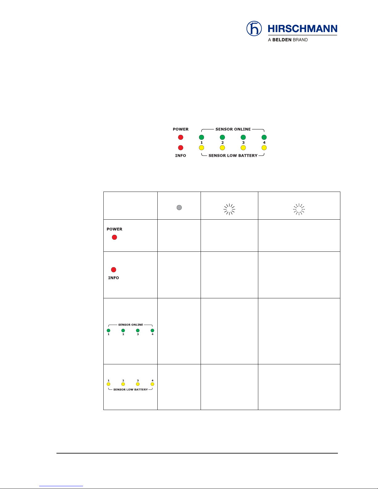
4.2 Status LEDs
There are 10 LEDs on the front panel of the device, which indicate the status of various operating
conditions.
The meaning of the signals can be taken from the table below. The signals apply only to normal
operation; deviating signals apply to programming mode:
off:
lights:
flashes:
No supply
voltage present
Supply voltage is
present
Hoist limit switch has
triggered
or
radio link to a wire-
less hoist limit switch
interrupted
During the system diagnosis
No sensor
registered to
this channel
Sensor registered to
this channel and
ready for operation
During the registration of new
wireless sensors
or
hoist limit switch on the indi-
cated channel is in ‘sleep’ mode
or
link with the sensor on the indi-
cated channel is interrupted
Batteries of the wire-
less sensor on this
channel are almost
exhausted!
(capacity < 6.5 %)
Replace the batter-
ies soon!
Table 2 Overview of status LED
© 2010 Hirschmann Automation and Control GmbH · Branch Office Ettlingen · E-mail: info.ecs@hirschmann.de 19/37
21-810-19-0003_421830_en (Rev A).doc / 2010-08-31 / Issue A / rk.

Commissioning
4.3 Opening/closing the housing
It is necessary to open the housing of the iFLEX TRS 14 in order to configure the output signals
and the radio link by means of the programming button and jumpers as described below.
First of all, disconnect the device from the power supply by pulling out the central plug.
IMPORTANT
Damage to the equipment due to non-compliance with the regulations for the handling of
equipment containing electrostatically sensitive devices (ESDs):
Pay attention to the following instructions if the device has to be opened during commis-
sioning:
• Discharge yourself (e.g. by touching an earthed object) before opening the device
• Hold the printed circuit board only by the edges
• Do not touch components or connector pins or tracks
Follow the procedure described below to open the housing:
Open the housing
HINT
A flat-blade screwdriver with a blade width of 4.5 - 5.5 mm is best suited for opening the
housing.
▲1. By means of a slight twisting movement of the
screwdriver, press the latches (on both sides of the
housing at the rear) carefully towards the housing
and in this way unlock the circuit board
▲2. The housing seal will be visible if the circuit
board has been unlocked correctly
© 2010 Hirschmann Automation and Control GmbH · Branch Office Ettlingen · E-mail: info.ecs@hirschmann.de 20/37
21-810-19-0003_421830_en (Rev A).doc / 2010-08-31 / Issue A / rk.
Table of contents
Other Hirschmann Transceiver manuals


Popular Transceiver manuals by other brands

Kenwood
Kenwood TS-680S instruction manual

timecode systems
timecode systems UltraSync BLUE user guide

Kenwood
Kenwood NEXEDGE NX-210 instruction manual

Radiant Communications
Radiant Communications DL227 SERIES user manual

Audio Technica
Audio Technica System 10 PRO Installation and operation

Yaesu
Yaesu FT-50 instruction manual


SIIG
SIIG FE-TXSC11 Quick installation guide

Midland
Midland BASE CAMP PMR446 manual

ELECRAFT
ELECRAFT P3 owner's manual

Entel
Entel HT502 user guide

SUPERYACHT SPARES
SUPERYACHT SPARES HT640 owner's manual

Northern Airborne Technology
Northern Airborne Technology NTX403 Series Installation and operation manual