Children should be supervised they do not play with the appliance.
It is recommended that the room be ventilated every 3 to 4 hours.
The appliance should not be installed in the laundry.
been given supervision or instruction concerning
use of the appliance by person responsible for their safe.
5
lDo not use any sprays such as insecticide, lacquer, hair spray or other flammable gases within
approximately one (1) meter from the system.
lIf circuit breaker or fuse is often activated, stop the system and contact your service contractor.
lDo not perform installation work, refrigerant piping work, drain piping and electrical wiring
connection without referring to our installation manual. If the instructions are not followed, it may
result in a water leakage, electric shock or a fire.
lCheck that the ground wire is securely connected. If the unit is not correctly grounded, it lead
electric shock. Do not connect the ground wiring to gas piping, water piping, lightning conductor
or ground wiring for telephone.
lConnect a fuse of specified capacity.
lDo not put any foreign material on the unit or inside the unit.
lMake sure that the outdoor unit is not covered with snow or ice, before operation.
lBefore performing any brazing work, check to ensure that there is no flammable material around.
When using refrigerant be sure to wear leather gloves to prevent cold injuries.
lProtect the wires, electrical parts, etc. from rats or other small animals.
If not protected, rats may gnaw at unprotected parts and which may lead to a fire.
lFix the cables securely. External forces on the terminals could lead to a fire.
lDo not install the indoor unit, outdoor unit, remote control switch and cable within approximately 3
meters from strong electromagnetic wave radiators such as medical equipment.
lSupply electrical power to the system to energize the oil heater for 12 hours before start-up after a
long shutdown.
lDo not step or put any material on the product.
lProvide a strong and correct foundation so that;
a. The outdoor unit is not on an incline.
b. Abnormal sound does not occur.
c. The outdoor unit will not fall down due to a strong wind or earthquake.
lDo not fasten flare nut hard. It may cause breakage with aged deterioration and refrigerant leakage.
Use a specified flare nut.
l
l
l
Regarding installation altitude below 1000 metres;
Regarding transport storage temperature within
-25 55 .
workstations, all this level does not exceed 70dB(A).
The A-weighted emission sound pressure level at
Regarding frequency of supply power within Hz of
rated frequency.
°C
~
±1%
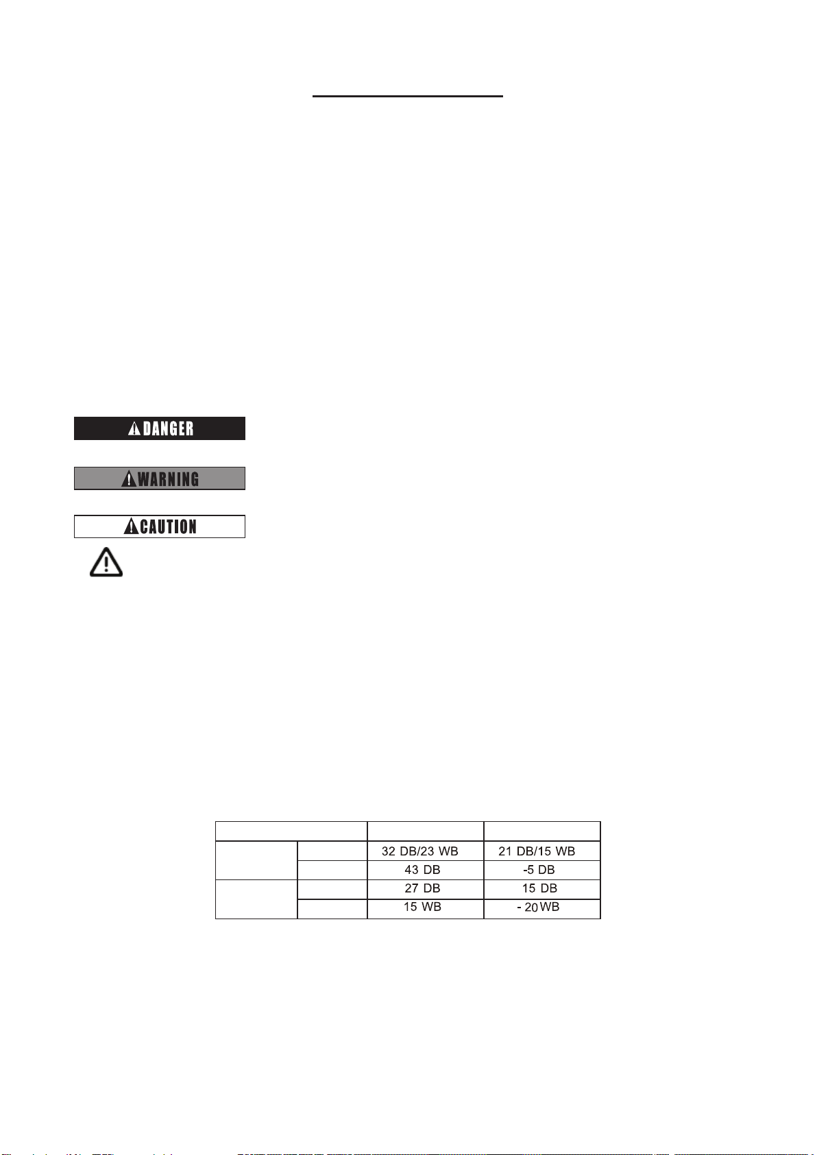
Operate the heat pump air conditioner within this range.
or lack of expericence and knowledge, unless they have
with reduced physical, sensory or mental capabilities,
The appliance is not to be used by children or person