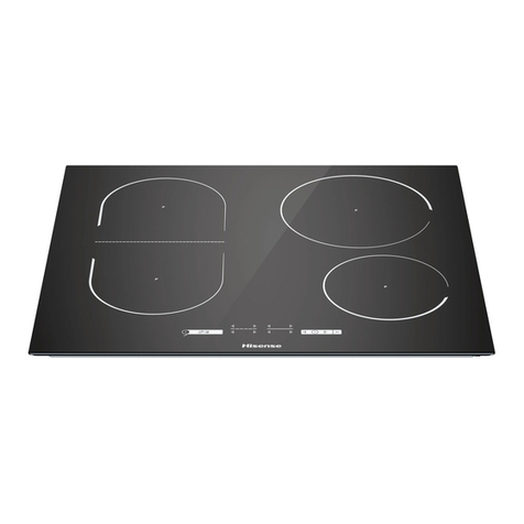
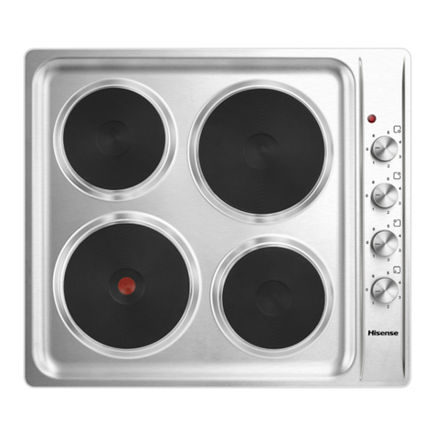
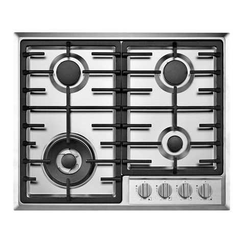
Hisense HHU60GASS Mounting instructions

MODEL NO.:HHU60GASS

CONTENTS
CLOSE-UP VIEW …………………………………..……………………………1
How To Use Your Appliance …………..………..………..………..……….…2
CLEANING AND MAINTENANCE……………………………………………3
ADVICE FOR INSTALLATION………………..………………………………5
GAS SECTION…………………………………..………………………………8
ELECTRICAL SECTION…………………………………..……………………11
CUT-OUT DIMENSION…………………………………..……………………12
WARRANTY CONDITIONS…………………………………..………………13

1
CLOSE-UP VIEW
Congratulations on choosing appliance, which you will find is dependable and easy to use. We
recommend that you read this manual for best performance and to extend the life of your
appliance. Thank you.
The ceramic glass can be damaged/cracked by external shock & vibration. Cast iron and
aluminum cookware with sharp edge may scratch the ceramic surface if they are dragged
across it.
1.Triple ring burner
2.Semi-rapid burner
3.Auxiliary Gas Burners
4.Control Knobs for Gas Burners
5.Igniter for Gas Burners
6.Safety Device - Activates if the flame accidentally goes out (spills, drafts, etc.), interrupting
the delivery of gas to the burner.
7.Burner Cap (enameled)
8.Burner flame distributor
NOTICE
The stainless steel grease pan and the cast-iron grill, located in the burner and grate packing
box, must be installed, respectively, below and above the electric heating element so that tile
element is enclosed between the two.

2
The position of the corresponding gas burner is indicated on each control knob.
It is prohibited to adjust the flame in the range between the Burner OFF and Burner ON
large flame positions.
How To Use Your Appliance
IGNITING THE BURNERS
GAS BURNERS
The burners differ in size and power. Choose the most appropriate one for the diameter of the
cookware being used.
The burner can be regulated with the corresponding control knob by using one of tile following
settings:
In these models the knob controls both ignition and the safety device. Proceed as follows to
ignite the burners:
1) Turn the chosen knob.
2) Keep the knob strongly pressed in for 3/4 seconds to permit the spark to light the gas that
exits from the flame tamer and to permit the thermocouple to heat up. Rotating the knob anti-
clockwise direction to the “High” setting.
3) Release the knob after about 3/4 seconds and adjust the flame as desired,
Repeat points 1 and 2 if the flame does not remain on.
Caution: If the burner accidently goes out, turn off the gas with the control knob and try to
light it again after waiting at least I minute.
Turn off a burner: turn the knob in the clockwise direction until it stops (it should be on the
“ ”setting).
USING THE BURNERS
For greater efficiency and less gas consumption use pots and pans with the right diameters for
the burners. Avoid having flames extending out from underneath the pans (refer to the table).

GENERAL
Cleaning and maintenance should be carried out with the appliance cold especially when
cleaning the enameled parts. Avoid leaving alkaline or acid substances (lemon juice, vinegar
etc.) on the surfaces. Avoid using acid or chlorine-based cleaning products.
To extend the life of the built-in gas hob, it is absolutely indispensable that it be cleaned
carefully and thoroughly on a frequent basis, keeping in mind the following:
ENAMELLED PARTS
All of the enameled parts must be washed only with a sponge and soapy water or with non-
abrasive products
BURNERS AND GRIDS
These parts can be removed and cleaned with appropriate products. After cleaning the
burners and their flame distributors must be well dried and correctly replaced. It is very
important to check that the burner flame distributor(8) and the burner cap(7) has been
correctly positioned ( fig. 2) -failure to do so can cause serious problems.
Check that the igniter(5) is always clean to ensure trouble-free sparking. Check that the
thermocouple(safety device 6) is always clean to ensure correct operation of the safety valves
(for models with safety device).
STAINLESS STEEL can be stained if it remains in contact with highly calcareous water or
aggressive detergents (containing phosphorous) for an extended period of time, it is
recommended that these parts be rinsed thoroughly with water and then dried well, It is also a
good idea to clean up any spills;
Both the safety device(6) and igniter(5) must be very carefully cleaned.
3
Table of recommended pans
Burner
Auxiliary
Semi rapid
Rapid
Triple ring
Ø Pan diameter in cm
from dia. 8 to dia. 14
from dia. 14 to dia. 20
from dia. 20 to dia. 28
Above dia. 26
AUTOMATIC SAFETY VALVES
This safety device automatically closes the gas valve if the inconvenience caused by failure to
comply with this rule.
CLEANING AND MAINTENANCE

4
GAS TAPS
Periodic lubrication of the gas taps must be carried out by specialist personnel only. In the
event of operating faults in the gas taps, call the Service Department.
GENERAL ADVICE
When the appliance is not being used; it is advisable to keep the gas tap closed.
If the gas tap becomes stiff, it is necessary to dismount it accurately, clean it with gasoline
and spread a bit of special grease resistant to high temperatures on it. This operation must
be executed by a qualified technician.
●
●
TRIPLE RING BURNER
The triple ring burner must be correctly positioned (seen fig.3); the burner rib must be entering
in their ligament as shown by the arrow. The burner correctly positioned must not rotate (fig.4).
Then position the burner cap A(center) and theburner cap B(outer) (fig.4).
CLEANING THE TRIPLE RING BURNER
Pay special attention to this burner: the four holes around the outside of the crown must
always be kept clean. When cleaning ,remove the flame divider (fig.4) and use a cotton bud,
toothbrush or some other item to clean out any incrustations or dirt from the four holes marked
“H” (fig.6). This procedure is necessary to ensure the burner functions correctly.

Greasing the Gas Valves
Over time, the gas valves may stick or become difficult to turn. If this is the case, the must be
cleaned on the inside and the regressed.
N.B.:This procedure must be performed by a technician authorized by the manufacturer.
ADVICE FOR INSTALLATION
●The appliance should be installed, regulated and adapted to function with other types of
gas by a QUALIFIED GAS INSTALLER.
Failure to comply with this condition will render the guarantee invalid.
The appliance must be installed in compliance with regulations in force in your country
and in observation of the manufacturer’s
instructions.
Always unplug the appliance before carrying out any maintenance operations or repairs.
Some appliances are supplied with a protective film on steel and aluminum parts. This
film must be removed before using the cooker.
The walls of the units must not be higher than work top and must be capable of resisting
temperatures of 75°C above temperature.
Do not install the appliance near inflammable materials (eg.curtains).
IMPORTANT:
●
●
●
●
●
●
INSTALLATION of BUILT-IN COOK TOPS
These tops are designed to be embedded into kitchen fixtures measuring 600 mm in depth.
5

●
In order to install the cooker top into the kitchen fixture, a hole with the dimensions shown on
the cutting size board has to be made, keeping in consideration the following:
Within the fixture, between the bottom side of the cooker top and the upper surface of any
other appliance or internal shelf there
must be a clearance of at least 30 mm;
The cooker top must be kept no less than 100 mm away from any side wall;
The hob must be installed at least 50 mm from the wall.
There must be a distance of at least 650 mm between the hob and any wall cupboard or
extractor hood positioned immediately
above.
It is essential to install a heat baffle between the bottom of the hob and the underlying unit.
●
●
●
●
INSTALLATION IN KITCHEN CABINET WITH DOOR (fig.8)
The fixture has to be made according to specific requirements in order to prevent the gas
burners from going out, even when the flame is turned down to minimum, due to pressure
changes while opening or closing the cupboard doors. It is recommended that a 30 mm
clearance be left between the cooker top and the fixture surface (fig.8).
6

INSTALLATION ROOM
The room where the gas appliance is to be installer must have a natural flow of air so that the
gas can burn. The flow of air must come directly from one or more openings made in the
out-side walls with a free area of at least 100c㎡. If the appliance does not have a no-flame
safety device this opening must have an area of at least 200c㎡. The openings should be near
the floor and preferably on the side opposite the exhaust for combustion products and must be
so made that they cannot be blocked from either the outside or the outside. When these
openings cannot be made the necessary air can come from an adjacent room which is
ventilated as required, as long as it is not a bedroom or a dangerous area. In this case the
kitchen door must allow the passage of the air.
DISCHARGING PRODUCTS OF COMBUSTION
Extractor hoods connected directly to the outside must be provided, to allow the products of
combustion of the gas appliance to be discharged (fig.9). If this is not possible, an electric fan
may be used, attached to the external wall or the window; the fan should have a capacity to
circulate air at an hourly rate of 3-5 times the total volume of the kitchen (fig.10). The fan can
only be installed if the room has suitable vents to allow air to enter, as described under the
heading “Installation room”.
SETTLING THE BUILT-IN GAS HOB FOR INSTALLATION
Every cooker top is provided with a set of tabs for fitting to the unit with thickness from 3 to 4 cm
and a seal with adhesive on one side.
-Remove burners and grids.
-Turn the cooker top over and rest the glass side on a cloth.
-Apply the self-adhesive seal “G” as illustrated in fig.11.
7
-Slot the cooker top into the unit and position.
-Position the cooker top in the recess and secure by means of
the brackets as shown in fig.12 (for 3 or 4 cm thick work top).
GAS SECTION
TYPES OF GASES
The gases normally used may be grouped, in view of their features in three families:
-L.P.G.(in cylinders) G30 28-30mbar
-NATURAL GAS(methane) G20 20mbar
IMPORTANT: By default, the built-in gas hob comes with nozzles suitable for LPG
The appliance should be installed, regulated and adapted to function with other types of gas by
a QUALIFIED INSTALLATION TECHNICIAN.
INSTALLATION
The appliance is predisposed and adjusted to operate with the gas indicated on the
specifications plate applied onto the appliance.
If the appliance must be operated with a gas different than that indicated on the plate, it is
necessary to execute the following operations:
gas connection
replacement of the injectors
regulating of the minimum
8

GAS CONNECTION
IMPORTANT: The connection must be executed by qualified technician according to the
relevant local standard.
The connection must be executed by qualified technician according to the relevant standard.
The fitting is made up of (see below figuration);
1 Elbow fitting “A”
1 adapter “B”
Gaskets “C”,”D”
A built in gas hob must be installed
in a room with adequate ventilation.
ORIENTATION of the ELBOW
The appliance is supplied with a gas connection oriented towards the centre of the built-in gas
hob. The connection to the gas supply must be effected only from this side or in vertical
position by turning the elbow downwards. To turn the elbow, follow these operations:
Loosen the nut
Turn the elbow
Lock the nut
Make sure that there are no
leakage by a soapy solution.
IMPORTANCES:
1.Never attempts to turn the elbow without having first slackened off the relative lock nipple.
2.The seals are the elements that guarantees the seal in the gas connection. It is
recommended that they be replaced whenever they shows even the slightest deformation or
imperfection.
3.After connecting to the mains, check that the couplings are correctly sealed, using soap
solution, but never a naked flame.
4.The connection with rigid metal pipes should not cause stresses to the bob ramp.
5.If the rubber tube is used for the gas connection:
Make sure the tube is snugly fit at both ends and use a standard tube clamp (not
supplied) to fasten it.
The rubber tube must be as short as possible, without contractions or kinks.
The rubber tube must never be at any point in its length in contact with the “hot” parts.
From time to time check to make sure that the rubber is in perfect condition.
●
●
●
●
●
●
●
●
●
●
●
●
●
9

OPERATIONS TO BE PERFORMED WHEN SUBSTITUTING THE INJECTORS
If the injectors are not supplied they can be obtained from the “Service Centre”.
Remove the gratings and the burner covers;
Using a wrench, substitute the nozzle injectors;
“J” (left Fig. 13) with those most suitable for the kind of gas for which it is to be used (see
Injector table).
The burners are conceived in such a way so as not to require the regulation of the primary air.
REGULATING THE BURNER MINIMUM SETTING
When switching from one type of gas to another, the minimum flow rate must also be correct
the flame should not go out even when passing suddenly from maximum to minimum flame. To
regulate the flame follow the instructions below:
1.Light the burner
2.Set the cock valve to minimum
On gas valves provided with adjustment screw in the centre of the shaft (fig.14)
Using a screwdriver with max. diameter 3 mm, turn the screw
inside the tap until the correct setting is obtained.
On gas valves provided with adjustment screw on the valve body (fig.15):
Turn the screw “A” to the correct setting with a screwdriver.Normally for G30 gas, fully tighten
the adjustment screw.
LUBRICATION OF THE GAS TAPS
If the gas tap becomes stiff, it is necessary to dismount it accurately clean it with gasoline and
spread a bit of special grease resistant to high temperatures on it.
The operations must be executed by a qualified technician.
10

Adapting the Built-in Gas Hob for Different Types of Gas
Burners and Nozzle Specifications
Burner
Auxiliary (Small) (A)
Semi rapid (Medium)
Rapid (R)
Triple Ring (TR)
Supply pressures
Thermal
power
(kW)
Nozzle
1/100
(mm)
Thermal
power
kW
Nozzle
1/100
(mm)
Thermal
power
kW
Nozzle
1/100
(mm)
Nozzle
1/100
(mm)
Nozzle
1/100
(mm)
0.90
1.88
2.40
3.40
69
97
110
123
0.90
1.88
2.40
3.40
69
97
110
123
50
68
78
91
0.90
1.88
2.40
3.40
44
64
72
86
43
60
68
83
20mbar 25mbar 30mbar 37mbar 50mbar
At 15°C and 1013 mbar-dry gas
P.C.I.G20 37.78 MJ/m³ P.C.I.G25.1 32.51 MJ/m³
P.C.I.G25 32.49 MJ/m³ P.C.I.G27 30.98 MJ/m³
ELECTRICAL SECTION
In the case of installation over a built-in electric oven, the electrical connections for the built-in
gas hob and oven should be independent, not only for safety purposes, but also to facilitate
removal of one or both in the future.
IMPORTANT: Connection to the electric power supply must be carried out by a qualified
technician and following the appropriate safety regulations.
DETAILS
Before carrying out the connection to the power supply, the voltage rating of the
appliance(stamped on the appliance identification plate) must be checked for
correspondence to the available mains supply voltage, and the mains electric wiring should
be capable of handling the hob's power rating (also indicated on the identification plate);
●
11
G20 G25 G30

The power point must be connected to a suitbale earth wiring, in conformity to current
safety regulations.
The colours of the wires in the built-in gas hob power cable may not correspond with the
colours marked on the terminals of your
electrical plug. The plug should in any case be wired as follows:
1.Connect the green/yellow wire to the terminal marked with the letter E or the earth
symbol or coloured green/yellow;
2.Connect the blue wire to the terminals marked with the letter N or cloured black;
3.Connect the brown wire to the terminal marked with the letter L or coloured red.
It is possible to connect the appliance directly to the mains supply by means of a heavey
duty switch with 3 mm minimum distance between contacts.
The power supply cord must not touch against any hot surfaces and must be placed so
that it’s temperature does not exceed 75℃ at any point along its length.
After having installed the appliance, the power switch or power plug must always be in a
accessible position.
NOTE: for connections to the mains power supply, never use adapters, reductions
or multiple power points as there may overheat and catch fire.
In the event that installation should require modifications to the mains supply wiring system
or if the power plug is not suitable for the type
of power point available, it is recommended that a qualified technician be called to carry
out substitution.
The technician will also have to verify that the cross-section of the electric cables on the
power point match the appliance’s power rating.
●
●
●
●
●
CUT-OUT DIMENSION
Model
HHU60GASS 552x470mm
CutOutDimension
(L x W, mm)
12

WARRANTY CONDITIONS
Hisense South Africa Warranty:
Major Household Appliances
Dear Customer,
Thank you for the purchase of a Hisense product.
The following conditions apply to the warranty on your Hisense product, which replaces any
other conditions printed or published elsewhere.
Please read through the conditions carefully and make sure you understand them.
If you have any questions regarding the warranty, please make contact with us on
0860 447 3673 or send us an e- mail on service@hisense.co.za.
Major Household Appliances include products such as Tv, Fridge and Freezers, Washing
Machines, Built in and freestanding ovens, hobs and stoves (excl. mini ovens) etc.
FAILURE TO USE A CERTIFIED ELECTRICIAN, CERTIFIED GAS INSTALLER OR
HISENSE AUTHORISED SERVICE AGENT OR GENUINE PARTS FOR
INSTALLATION OR SERVICE VOIDS THE GUARANTEE
Conditions of your Warranty:
From January 2014, Hisense warrants the product against faulty manufacture and / or
defective material and the working of your product for 36 months (3 years) from the date of
purchase, provided it is used for its intention and for domestic use only. A further 12 months
warranty can be obtained (4th year warranty) if the consumer has registered their warranty
successfully with Hisense South Africa within the first 6 months of date of purchase.
Please visit us on www.hisense.co.za for product registration or SMS the word HICARE to
48868 and you will receive a link to our mobi site with easy to follow instructions to complete
registration.
Bar fridges, mini ovens, free standing stoves, extractors ,sound bars and microwaves carry a
2-year warranty — please refer to our latest Small Appliances warranty conditions.
Units that are supplied through rental channels carry a 2-year warranty only, please consult
with these channels or Hisense South Africa regarding the warranty period and conditions.
The warranty does not apply to Hisense air conditioners, please contact our agents / original
retaileror distributor for warranty conditions for air conditioners.
NOTE: The 4-year warranty does not apply to all dealers, please refer back to the dealer or
distributor where the unit was purchased from for the correct warranty period and conditions
or contact Hisense South Africa.
For warranty conditions, period and queries in any other country, outside South Africa, please
consult the in country local Distributor.
1. For product purchased before January 2014, we warrant the working of the unit for a
minimum of 12 months (1 year), but may vary from retailer to retailer. Please consult with
the original dealer the unit was purchased from to confirm the warranty period or contact us
if you unsure regarding your warranty on [email protected].
2. Hisense bar fridges, microwaves, extractors and mini-ovens, are not repaired. Kindly return
Augustus 2017
13

it with the original proof of purchase to the store is was bought from, within the warranty
period from date of purchase. It may be required to log a service call for inspection and
verification for the reported fault.
3. Hisense is in support of the Consumer Protection Act 68 of 2008, and in the first 6 (six)
months from date of purchase, for valid warranty claims, the product will may be repaired or
exchanged by the Hisense, or credited by the dealer / store once approved by Hisense. For
the remainder of the warranty period (after the first 6 (six) months from date of purchase)
the product may be repaired or exchanged by Hisense, or be requested to be credited or
exchanged by the store or dealer where original purchase was made, on approval from
Hisense.It may be required to log a service call for inspection and verification for the
reported fault.
4. The above warranty conditions is only applicable for South Africa. For Namibia, Botswana,
Lesotho and Swaziland, a 2 year warranty applies for repair within the 2 year warranty
period, and exchange or credit can only take place on approval from Hisense. The
Customer Protection Act does not apply to countries outside South Africa as mentioned
elsewhere is the warranty conditions. For warranty conditions, period and queries in any
other country, outside South Africa, please consult the in country local Distributor.
5. The warranty on the product is supplied on condition that only Hisense authorised service
agents are at all times used in connection with the product for any repairs or inspections
where applicable.
Any repairs conducted on the Hisense products by Hisense authorised service agents, will
carry a 3 month warranty on the labour and parts for the completed repair, from the date the
repair was completed and does not extend the warranty nor does it start a new warranty.
Parts removed during warranty repairs become the property of Hisense.
6 The warranty will no longer be valid, and Hisense will not be responsible for damage or
injury of any kind resulting from electricity fluctuations and surges, lightning strikes, faults in
the building wiring,faulty installations, and improper use of controls and or failure to use the
product in accordance with the operating instructions and or general misuse and or abuse,
or if not used for domestic purposes only, or for damage caused by a superior force (vis
maior). Where the product has been infested with insects or pests. The product is physically
damaged after it left the store. If water or liquid caused the damage to the product. If the
warrantee seal is tampered with. Any repair or tampering by an unauthorised person or
attempt to repair or tamper with the equipment, or use of parts not supplied by authorised
agents, or alterations or modification to the equipment, shall render the warranty null and
void.
7 After the first 6 (six) months from the date of purchase, this warranty does not apply to any
accessories or to light bulbs, loose glass, glass doors and enamelled surfaces, filters,
handles,doors, crispers or shelves, tv stands or brackets, remotes, 3D glasses, any
accessories and other parts subject to wear and tear or discolouring. Damage caused by
abrasive and highly concentrated cleaners and/or cleaning materials or cleaners prohibited
by the user manual, will void the warranty.
8 After 6 (six) months from the date of purchase of the product the liability of Hisense under
this warranty is limited to the replacement and/or repair of the defective parts within the
warranty period and does not extend to the installation or removal of the product.
The warranty shall be available only to the original purchaser of the product from an
authorised Hisense Dealer or Distributor and only where the product has been retained for
use in the Republic of South Africa. For warranty conditions, period and queries in any other
country, outside South Africa, please consult the in country local Distributor.
Important note: In order to make sure you get to use the warranty supplied with your product
and for the protection of your product when returning it, please keep the box your product
came in as well as the packaging and all accessories and ensure to retain the original proof of
purchase.
14

Table of contents
Other Hisense Hob manuals

Hisense
Hisense BI6062HIXUK User manual

Hisense
Hisense HBO60201 Operating manual

Hisense
Hisense E6431C User manual

Hisense
Hisense HHU60CEEC Operating manual

Hisense
Hisense I8433C User manual

Hisense
Hisense I6433C7 User manual

Hisense
Hisense I6337C Manual

Hisense
Hisense GG722B Operating manual

Hisense
Hisense CT41SC User manual

Hisense
Hisense HGH641SS Mounting instructions
Popular Hob manuals by other brands

Fiori
Fiori P44W Instructions and advice for the use, installation and maintenance

Electrolux
Electrolux Y62IS443 user manual

Electrolux
Electrolux EHF6140FOK user manual

Exquisit
Exquisit EKC801-5Z Instructions for use and installation

ROBLIN
ROBLIN MAESTRO 830 N user manual

Platinum
Platinum AUPL-GF61SS user manual