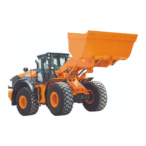
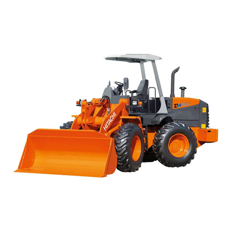
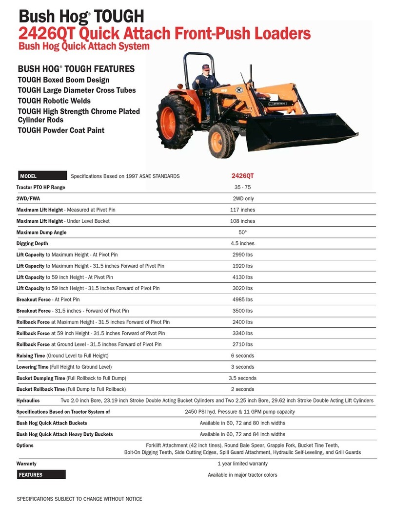
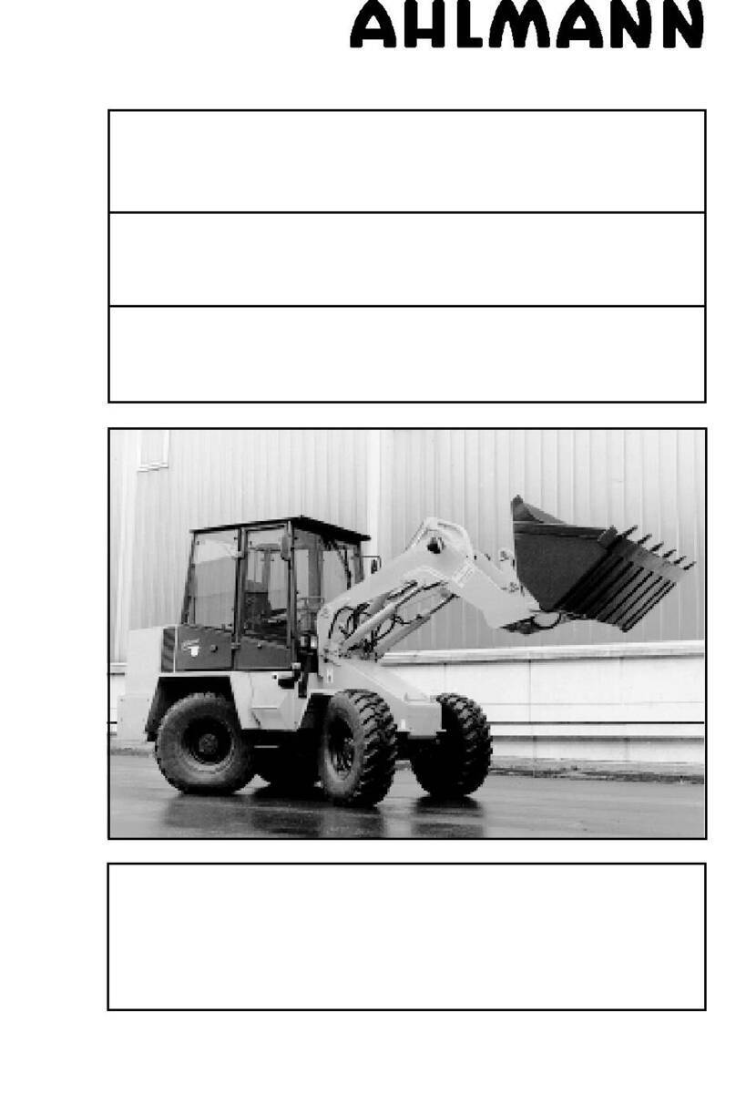
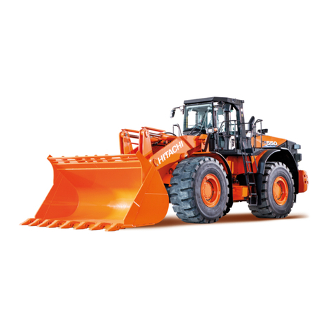
Hitachi ZW 550-G User manual

93216-00225
May 2011
Foreword
To ensure good machine performance, reduce failures or problems, and prolong the service life of each component,
it is necessary to operate the machine as is directed in the Operator and Maintenance Manual.
To effectively diagnose and repair the machine, it is important to follow the guidelines laid out in this Shop Manual.
General Information
Function and structure
For the engine, refer to the engine Shop Manual provided by the engine manufacturer.
The purpose of this manual is to provide information on the product and the correct maintenance and repair meth-
ods. Please read this manual to ensure correct troubleshooting and good repair service.
This manual will be periodically reviewed and revised for more satisfactory content. If you have any opinion or
requests, please inform us.
Machine Specification
Market Serial numbers Remarks
Asia and Africa 0101 and up Powered by CUMMINS QSK19-C Engine
Europe 9001 and up
Find manuals at https://best-manuals.com

Safety Symbols
An accident may occur if you disregard safety rules.
In this manual, several expressions are used according to levels of danger for inspection and repair work as shown
below. Read the work procedures and cautions described in this manual, and take preventive measures against
possible problems before starting service work.
We cannot predict all possible accidents or incidents that may occur during service work. Therefore, an accident that
is not specifically mentioned in this manual may occur. To protect yourself from all accidents, be careful when doing
service work.
DANGER
This danger symbol identifies special warnings or
procedures which, if not strictly observed, will result
in death or serious injury.
WARNING
This warning symbol identifies special warnings or
procedures which, if not strictly observed, could result
in death or serious injury.
CAUTION
This caution symbol identifies special instructions or
procedures which, if not strictly observed, may result
in minor or moderate injury.
IMPORTANT
This important symbol identifies special instructions
or procedures which, if not correctly followed, may
result in serious machine damage.
Find manuals at https://best-manuals.com

CONTENTS
General Information .............................................................................................................................................. 00-1
How to Use Manual ........................................................................................................................................... 00-2
Safety precautions ...................................................................................................................................... 00-2
Symbols ...................................................................................................................................................... 00-3
Outline ............................................................................................................................................................... 00-4
Layout of main components ........................................................................................................................ 00-4
Inspection and maintenance table .............................................................................................................. 00-5
Recommended lubricants ........................................................................................................................... 00-8
Coolant ....................................................................................................................................................... 00-9
Lubrication chart ....................................................................................................................................... 00-10
Weight of main components ......................................................................................................................00-11
Bolt tightening torque ................................................................................................................................ 00-12
Hose band tightening torque ..................................................................................................................... 00-16
Liquid gasket and screw lock agent .......................................................................................................... 00-17
Measurement for Performance Check .................................................................................................................. 03-1
Cautions on Safety ............................................................................................................................................ 03-2
Standard Measurement Values for Performance Check ................................................................................... 03-3
Function & Structure Chassis Group ..................................................................................................................... 12-1
Front Chassis .................................................................................................................................................... 12-2
Loading linkage ........................................................................................................................................... 12-2
Loading linkage pin ..................................................................................................................................... 12-4
Rear Chassis .................................................................................................................................................... 12-5
Fuel tank ..................................................................................................................................................... 12-5
Floor board mount ....................................................................................................................................... 12-6
Center Pin ......................................................................................................................................................... 12-7
Upper center pin ......................................................................................................................................... 12-7
Lower center pin ......................................................................................................................................... 12-7
Dust seal ..................................................................................................................................................... 12-8
Check & Adjustment Chassis Group ..................................................................................................................... 13-1
Linkage Pin ....................................................................................................................................................... 13-2
Liner ............................................................................................................................................................ 13-2
Find manuals at https://best-manuals.com

Center Pin ......................................................................................................................................................... 13-6
Adjusting shim ............................................................................................................................................. 13-6
Installing bearing cover ............................................................................................................................... 13-6
Installing bearing outer ring ......................................................................................................................... 13-6
Function & Structure Power Group ....................................................................................................................... 22-1
Power Line ........................................................................................................................................................ 22-2
Engine / Transmission ....................................................................................................................................... 22-3
Engine / transmission mount ....................................................................................................................... 22-3
Radiator ............................................................................................................................................................. 22-4
Radiator mount ............................................................................................................................................ 22-5
Propeller Shaft .................................................................................................................................................. 22-6
First propeller shaft assembly ..................................................................................................................... 22-7
Second propeller shaft assembly ................................................................................................................ 22-8
Third propeller shaft assembly .................................................................................................................. 22-10
Axle Assembly ................................................................................................................................................. 22-11
Axle Support .................................................................................................................................................... 22-14
Differential Gear .............................................................................................................................................. 22-20
Function of differential gear ....................................................................................................................... 22-24
Operation of differential gear ..................................................................................................................... 22-24
Check & Adjustment Power Group ........................................................................................................................ 23-1
Engine ............................................................................................................................................................... 23-2
Measuring engine speed ............................................................................................................................. 23-2
Measuring engine oil pressure .................................................................................................................... 23-2
Propeller Shaft .................................................................................................................................................. 23-3
Propeller shaft phase .................................................................................................................................. 23-3
Second propeller shaft alignment ................................................................................................................ 23-3
Tightening torque ........................................................................................................................................ 23-4
Axle ................................................................................................................................................................... 23-5
Axle nut tightening procedure ..................................................................................................................... 23-5
Find manuals at https://best-manuals.com

Function & Structure Torque Converter and Transmission Group ........................................................................ 32-1
Torque Converter .............................................................................................................................................. 32-2
Torque converter structure .......................................................................................................................... 32-3
Power flow path .......................................................................................................................................... 32-3
Torque multiplication ................................................................................................................................... 32-3
Torque Converter Gear Pump ........................................................................................................................... 32-4
Gear pump specifications ........................................................................................................................... 32-4
Transmission ..................................................................................................................................................... 32-5
Clutch combination ..................................................................................................................................... 32-6
Planetary gear ............................................................................................................................................. 32-6
Shift lever position ....................................................................................................................................... 32-6
Power up switch operation .......................................................................................................................... 32-6
Gear train and number of teeth ................................................................................................................... 32-7
Clutch Pack ..................................................................................................................................................... 32-10
Power Flow Path in the Transmission ..............................................................................................................32-11
Forward ......................................................................................................................................................32-11
Reverse ..................................................................................................................................................... 32-14
Hydraulic System Diagram ............................................................................................................................. 32-16
Hydraulic Circuit Diagram ............................................................................................................................... 32-17
T/C and T/M Oil Circulation ............................................................................................................................. 32-18
Oil flow in the torque converter line ........................................................................................................... 32-19
Oil flow to the clutch .................................................................................................................................. 32-19
Modulator Valve Unit ....................................................................................................................................... 32-20
Interior schematic (not exact representation) ............................................................................................ 32-22
Modulation Mechanism ................................................................................................................................... 32-23
Modulator valve function ........................................................................................................................... 32-23
Modulator valve operation ......................................................................................................................... 32-25
Clutch Solenoid Valve ..................................................................................................................................... 32-26
Check & Adjustment Torque Converter and Transmission Group ........................................................................ 33-1
Clutch Oil Pressure and Time Lag .................................................................................................................... 33-2
Measuring clutch oil pressure ..................................................................................................................... 33-2
Measuring clutch time lag ........................................................................................................................... 33-4
Find manuals at https://best-manuals.com

Function & Structure Hydraulic Group ................................................................................................................... 42-1
Flushing Hydraulic Circuit ................................................................................................................................. 42-2
Purpose of flushing ..................................................................................................................................... 42-2
Cautions on Hydraulic Parts Replacement ....................................................................................................... 42-3
Hydraulic Circuit Symbols ................................................................................................................................. 42-4
Hydraulic lines ............................................................................................................................................. 42-4
Pumps & motors .......................................................................................................................................... 42-4
Cylinders ..................................................................................................................................................... 42-4
Operation methods ...................................................................................................................................... 42-5
Pressure control valve ................................................................................................................................. 42-5
Flow control valve ....................................................................................................................................... 42-5
Directional control valve .............................................................................................................................. 42-6
Check valve ................................................................................................................................................. 42-6
Miscellaneous hydraulic symbols ................................................................................................................ 42-7
Hydraulic System Operation ............................................................................................................................. 42-8
Hydraulic system operation outline ............................................................................................................. 42-8
Layout of Hydraulic Units ................................................................................................................................ 42-10
Hydraulic Tank ................................................................................................................................................. 42-11
Hydraulic tank specifications ..................................................................................................................... 42-11
Hydraulic oil level check ............................................................................................................................ 42-11
Hydraulic tank (S/N 0101~0200, 9001~) ................................................................................................... 42-12
Hydraulic tank (S/N 0201~) ....................................................................................................................... 42-14
Hydraulic Pump ............................................................................................................................................... 42-16
Loading and pilot and brake pump ............................................................................................................ 42-17
Pump specifications .................................................................................................................................. 42-17
Steering pump ........................................................................................................................................... 42-18
Steering pump specifications .................................................................................................................... 42-18
Hydraulic pump principle ........................................................................................................................... 42-19
Hydraulic pump wear plate ........................................................................................................................ 42-20
Hydraulic pump bushing lubrication .......................................................................................................... 42-20
Hydraulic Cylinder ........................................................................................................................................... 42-21
Boom cylinder ........................................................................................................................................... 42-21
Bucket cylinder .......................................................................................................................................... 42-21
Steering cylinder ....................................................................................................................................... 42-22
Hydraulic cylinder specifications ............................................................................................................... 42-22
Find manuals at https://best-manuals.com

Loading System .............................................................................................................................................. 42-23
Reducing Valve (for Pilot Pressure) ................................................................................................................ 42-24
Pilot Valve (S/N 0101~0140, 9001~9020) ....................................................................................................... 42-25
Pilot valve operation .................................................................................................................................. 42-27
Pilot valve detent magnet solenoid ........................................................................................................... 42-29
Detent adjustment procedure .................................................................................................................... 42-29
Pilot valve (S/N 0141~0172, 9021~) ............................................................................................................... 42-30
Pilot valve operation .................................................................................................................................. 42-32
Pre-detent and detent magnet solenoid .................................................................................................... 42-34
Pilot valve (S/N 0173~0176) ........................................................................................................................... 42-35
Pilot valve (S/N 0177~) ................................................................................................................................... 42-40
Multiple Control Valve (KML35A/2T103) ......................................................................................................... 42-45
Multiple control valve specifications .......................................................................................................... 42-46
Multiple control valve main relief valve ..................................................................................................... 42-47
Multiple control valve overload relief valve ............................................................................................... 42-49
Multiple control valve bucket spool ........................................................................................................... 42-52
Multiple control valve boom spool ............................................................................................................. 42-54
Adapter (Orifice) .............................................................................................................................................. 42-57
Vibration Damper (OPT) ................................................................................................................................. 42-58
Vibration damper operation ....................................................................................................................... 42-59
Vibration damper hydraulic line ................................................................................................................. 42-68
Steering System .............................................................................................................................................. 42-69
Orbitrol®.......................................................................................................................................................... 42-70
Orbitrol®structure ..................................................................................................................................... 42-70
Orbitrol®specifications .............................................................................................................................. 42-71
Orbitrol®operation .................................................................................................................................... 42-72
Orbitrol®feed-back mechanism operation ................................................................................................ 42-74
Steering speed and flow rate control ........................................................................................................ 42-75
Hydraulic pump oil amount and steering force .......................................................................................... 42-75
Orbit rotor operation principle ................................................................................................................... 42-76
Steering Valve (KVS32-A4.0/21) ..................................................................................................................... 42-77
Steering valve operation ........................................................................................................................... 42-79
Steering spool variable throttle ................................................................................................................. 42-81
Steering valve flow control spool .............................................................................................................. 42-82
Steering valve main relief valve ................................................................................................................ 42-83
Find manuals at https://best-manuals.com

Steering valve overload relief valve .......................................................................................................... 42-85
Steering pilot circuit and its operation ....................................................................................................... 42-87
Stop Valve ....................................................................................................................................................... 42-89
Stop valve function .................................................................................................................................... 42-91
Stop valve operation ................................................................................................................................. 42-92
Reducing Valve (for Orbitrol®) ......................................................................................................................... 42-93
Steering Line Filter .......................................................................................................................................... 42-94
Fan Motor System ........................................................................................................................................... 42-95
Fan Motor Line (S/N 0101~0120, 9001~9010) ............................................................................................... 42-96
Fan Motor (GM30C) .................................................................................................................................. 42-98
Valve Assembly (for Fan Motor) ................................................................................................................ 42-99
Relief Valve (Two-step Relief) ................................................................................................................. 42-100
Solenoid Valve (for Fan Speed Control) .................................................................................................. 42-103
Fan Motor Line (S/N 0121~, 9011~) .............................................................................................................. 42-104
Fan Motor (GM30W) ............................................................................................................................... 42-106
Thermo Sensing Valve ............................................................................................................................ 42-107
Fan Motor Relief Valve Assembly ........................................................................................................... 42-109
Emergency Steering .......................................................................................................................................42-111
Emergency steering operation ................................................................................................................ 42-112
Emergency steering hydraulic line .......................................................................................................... 42-112
Emergency steering oil flow .................................................................................................................... 42-113
Emergency steering pump ...................................................................................................................... 42-115
Check & Adjustment Hydraulic Group ................................................................................................................... 43-1
Loading/Steering Circuit Relief Valve ................................................................................................................ 43-2
Loading circuit relief valve setting pressures .............................................................................................. 43-2
Steering circuit relief valve setting pressures .............................................................................................. 43-7
Hydraulic Cylinder ........................................................................................................................................... 43-11
Cylinder natural drift .................................................................................................................................. 43-11
Stop Valve ....................................................................................................................................................... 43-13
Stop valve adjustment procedure .............................................................................................................. 43-13
Fan Motor Revolution ...................................................................................................................................... 43-14
Fan maximum revolution measurement (S/N 0101~0120, 9001~9010) ................................................... 43-14
Fan maximum revolution measurement (S/N 0121~, 9011~) ................................................................... 43-16

Function & Structure Brake Group ........................................................................................................................ 52-1
Brake System Outline ....................................................................................................................................... 52-2
Service brake .............................................................................................................................................. 52-2
Parking brake .............................................................................................................................................. 52-2
Auto brake .................................................................................................................................................. 52-2
Adjustment of axle internal pressure ........................................................................................................... 52-2
Brake Units Layout ............................................................................................................................................ 52-3
Unloader Valve .................................................................................................................................................. 52-4
Unloader valve operation ............................................................................................................................ 52-6
Reducing valve ................................................................................................................................................. 52-7
Valve Unit (Main Brake Manifold Block) ............................................................................................................ 52-8
Brake Accumulator Line .................................................................................................................................... 52-9
Accumulator .............................................................................................................................................. 52-10
In-Line Filter ...............................................................................................................................................52-11
Brake Valve ..................................................................................................................................................... 52-12
Brake main valve (left pedal) .................................................................................................................... 52-12
Brake pilot valve (right pedal) ................................................................................................................... 52-13
Brake valve performance chart ................................................................................................................. 52-14
Brake valve outline .................................................................................................................................... 52-15
Stop Lamp Pressure Switch ............................................................................................................................ 52-18
Pressure switch (for stop lamp) ................................................................................................................ 52-18
Pressure switch (for Declutch) .................................................................................................................. 52-19
Service Brake .................................................................................................................................................. 52-20
Service brake operation ............................................................................................................................ 52-20
Service brake friction plate ........................................................................................................................ 52-21
Service brake steel plate ........................................................................................................................... 52-22
Service brake piston ................................................................................................................................. 52-23
Service brake pedal stroke adjusting mechanism ..................................................................................... 52-24
Parking Brake ................................................................................................................................................. 52-28
Parking brake operation ............................................................................................................................ 52-30
Parking brake solenoid valve .................................................................................................................... 52-31
Parking Brake Manual Release ...................................................................................................................... 52-32
Parking Brake Spring Chamber ...................................................................................................................... 52-34
Brake Circuit Check Valve ............................................................................................................................... 52-35

Auto Brake ...................................................................................................................................................... 52-36
Auto brake operation set value ................................................................................................................. 52-36
Auto brake circuit ...................................................................................................................................... 52-36
Solenoid valve (for auto brake circuit) ....................................................................................................... 52-37
Shuttle Valve ................................................................................................................................................... 52-38
Check & Adjustment Brake Group ........................................................................................................................ 53-1
Brake Circuit Oil Pressure ................................................................................................................................. 53-2
Unloader valve setting pressure .................................................................................................................. 53-2
Brake valve oil pressure .............................................................................................................................. 53-6
Service Brake .................................................................................................................................................... 53-8
Service brake performance check ............................................................................................................... 53-8
Service brake friction plate wear measurement .......................................................................................... 53-9
Parking Brake .................................................................................................................................................. 53-12
Parking brake performance check ............................................................................................................ 53-12
Parking brake clearance adjustment ......................................................................................................... 53-14
Function & Structure Electrical Group ................................................................................................................... 62-1
How to Use Electrical Wiring Diagram .............................................................................................................. 62-2
Electrical Cable Color Codes ............................................................................................................................ 62-8
Electrical Circuit Symbols .................................................................................................................................. 62-9
Sensor Mount .................................................................................................................................................. 62-10
Fuse ................................................................................................................................................................ 62-11
Fuse box ................................................................................................................................................... 62-12
Fusible link ................................................................................................................................................ 62-13
Engine Start Circuit ......................................................................................................................................... 62-14
Engine start circuit diagram ....................................................................................................................... 62-14
Neutral starter ........................................................................................................................................... 62-15
Starter switch ............................................................................................................................................. 62-16
Battery relay .............................................................................................................................................. 62-17
Alternator I terminal wire ........................................................................................................................... 62-17
Diode unit .................................................................................................................................................. 62-18
Neutral relay .............................................................................................................................................. 62-18
Magnet switch ........................................................................................................................................... 62-19
Voltage relay ............................................................................................................................................. 62-19

Power Generating/Charging Circuit ................................................................................................................ 62-21
Alternator .................................................................................................................................................. 62-21
ECM (Engine Controller) ................................................................................................................................. 62-22
Function of ECM ....................................................................................................................................... 62-22
Connection diagram .................................................................................................................................. 62-22
Monitor lamp test ...................................................................................................................................... 62-23
Failure diagnosis ....................................................................................................................................... 62-24
Quantum fault code information ................................................................................................................ 62-29
Power mode change ................................................................................................................................. 62-36
Accelerator pedal ...................................................................................................................................... 62-37
Accelerator pedal ...................................................................................................................................... 62-39
Transmission Control Circuit (S/N 0101~0153, 9001~) .................................................................................. 62-41
Controller .................................................................................................................................................. 62-41
Controller connection diagram .................................................................................................................. 62-43
Controller function ..................................................................................................................................... 62-44
Monitor controller ...................................................................................................................................... 62-61
Transmission Control Circuit (S/N 0154~) ...................................................................................................... 62-62
Machine control unit (MCU) ...................................................................................................................... 62-62
Machine control unit (MCU) connection diagram ...................................................................................... 62-64
Monitor Circuit ................................................................................................................................................. 62-66
Monitor controller (S/N 0101~0153, 9001~) .............................................................................................. 62-69
Monitoring sensor and switch ................................................................................................................... 62-71
Instrument Panel and Switch .......................................................................................................................... 62-72
Instrument panel ....................................................................................................................................... 62-72
Instrument panel rear surface ................................................................................................................... 62-73
Gauge circuit ............................................................................................................................................. 62-74
Fuel gauge circuit ...................................................................................................................................... 62-75
Tachometer circuit ..................................................................................................................................... 62-76
Electrical Detent Circuit ................................................................................................................................... 62-77
Bucket leveler ........................................................................................................................................... 62-77
Boom kick-out (option) .............................................................................................................................. 62-78
Detent solenoid ......................................................................................................................................... 62-79
Diode ............................................................................................................................................................... 62-80
Diode check method ................................................................................................................................. 62-81

Caution for diode check method ............................................................................................................... 62-81
Surge voltage and surge suppression diodes ........................................................................................... 62-83
Diagnostic System .......................................................................................................................................... 62-84
Transmission controller ............................................................................................................................. 62-84
Monitor controller ...................................................................................................................................... 62-88
Diagnostic failure history indication and deletion ...................................................................................... 62-91
Diagnostic switch ...................................................................................................................................... 62-93
MODM (S/N 0154~) ........................................................................................................................................ 62-94
MODM function ......................................................................................................................................... 62-94
Monitor Changeover .................................................................................................................................. 62-94
MODM: input/output monitor - input/output signal correspondence table ............................................... 62-101
Check & Adjustment Electrical Group ................................................................................................................... 63-1
Cautions Regarding Electric Circuit Check ....................................................................................................... 63-2
Disconnecting or reinstalling connector ...................................................................................................... 63-2
How to attach the probes of the circuit tester .............................................................................................. 63-4
Electrical Transmission Control System Troubleshooting Flowchart ................................................................. 63-5
Standard troubleshooting flowchart ............................................................................................................. 63-5
Transmission Controller Abnormal Operation Judgment .................................................................................. 63-6
Transmission controller check ..................................................................................................................... 63-6
Transmission controller LED indicator ........................................................................................................ 63-8
Electrical Circuit Check ................................................................................................................................... 63-10
Shift lever input electrical circuit check ..................................................................................................... 63-10
Inching (Declutch) input electrical circuit check ........................................................................................ 63-12
QUAD switch input electrical circuit check ................................................................................................ 63-14
Machine speed sensor input electrical circuit check ................................................................................. 63-15
Clutch solenoid valve output electrical circuit check ................................................................................. 63-16
Modulator valve output electrical circuit check .......................................................................................... 63-18
Neutral relay electrical circuit check .......................................................................................................... 63-20
Parking brake electrical circuit check ........................................................................................................ 63-21
Auto brake electrical circuit check ............................................................................................................. 63-23
Gauge circuit electrical circuit check ......................................................................................................... 63-25
Fuel level gauge electrical circuit check .................................................................................................... 63-27
Bucket positioner electrical circuit check ................................................................................................... 63-29

Function & Structure Operator Station Group ....................................................................................................... 72-1
Cabin ................................................................................................................................................................. 72-2
Glass ........................................................................................................................................................... 72-4
Wiper mount ................................................................................................................................................ 72-7
Wiper motor ................................................................................................................................................ 72-8
Operator Seat ................................................................................................................................................. 72-10
Steering and Transmission Shift Lever ............................................................................................................72-11
Tilt case ..................................................................................................................................................... 72-12
Column shaft ............................................................................................................................................. 72-13
Shift lever .................................................................................................................................................. 72-13
Air Conditioner ................................................................................................................................................ 72-14
Air conditioner components ...................................................................................................................... 72-14
Air conditioner structure ............................................................................................................................ 72-15
Cooling mechanism .................................................................................................................................. 72-20
Cooling circuit ........................................................................................................................................... 72-22
Electrical circuit ......................................................................................................................................... 72-23
Air conditioner functions of components ................................................................................................... 72-24
Charge of refrigerant ................................................................................................................................. 72-51
Air conditioner troubleshooting ................................................................................................................. 72-66
Check & Adjustment Operator Station Group ....................................................................................................... 73-1
Air Conditioner .................................................................................................................................................. 73-2
Adjustment of lubricating oil quantity when components of air conditioner are replaced ............................ 73-2
Adjustment of air gap (between hub and rotor) in compressor magnetic clutch ......................................... 73-5
Parts to be replaced periodically ................................................................................................................. 73-6
Cross-section drawing & Diagrams ....................................................................................................................... 92-1
Axle Assembly .................................................................................................................................................. 92-2
Torque Converter and Transmission ................................................................................................................. 92-3
Loading/Steering Hydraulic Line (S/N 0101~0120) ........................................................................................... 92-4
Loading/Steering Hydraulic Circuit (S/N 0121~) ............................................................................................... 92-5
Loading/Steering Hydraulic Circuit (S/N 9001~9010) ....................................................................................... 92-6
Loading/Steering Hydraulic Circuit (S/N 9011~) ................................................................................................ 92-7
Brake Circuit ..................................................................................................................................................... 92-8

Electrical Wiring Diagram (1/2) (S/N 0101~0120) ............................................................................................. 92-9
Electrical Wiring Diagram (2/2) (S/N 0101~0120) ........................................................................................... 92-10
Electrical Wiring Diagram (1/2) (S/N 0121~0124) ........................................................................................... 92-11
Electrical Wiring Diagram (2/2) (S/N 0121~0124) ........................................................................................... 92-12
Electrical Wiring Diagram (1/2) (S/N 0125~0153) ........................................................................................... 92-13
Electrical Wiring Diagram (2/2) (S/N 0125~0153) ........................................................................................... 92-14
Electrical Wiring Diagram (1/3) (S/N 0154~) ................................................................................................... 92-15
Electrical Wiring Diagram (2/3) (S/N 0154~) ................................................................................................... 92-16
Electrical Wiring Diagram (3/3) (S/N 0154~) ................................................................................................... 92-17
Electrical Wiring Diagram (1/2) (S/N 9001~9010) ........................................................................................... 92-18
Electrical Wiring Diagram (2/2) (S/N 9001~9010) ........................................................................................... 92-19
Electrical Wiring Diagram (1/2) (S/N 9011~) ................................................................................................... 92-20
Electrical Wiring Diagram (2/2) (S/N 9011~) ................................................................................................... 92-21
Electrical Wiring Diagram Abbreviation Chart (S/N 0101~0153, 9001~) ........................................................ 92-22
Electrical Wiring Diagram Abbreviation Chart (S/N 0154~) ............................................................................. 92-23
Electrical Wiring Diagram (CAB) ..................................................................................................................... 92-24
Electrical Connection Diagram (S/N 0101~0120) ........................................................................................... 92-26
Electrical Connection Diagram (S/N 0121~0124) ........................................................................................... 92-27
Electrical Connection Diagram (S/N 0125~0153) ........................................................................................... 92-28
Electrical Connection Diagram (S/N 0154~) ................................................................................................... 92-29
Electrical Connection Diagram (S/N 9001~9010) ........................................................................................... 92-30
Electrical Connection Diagram (S/N 9011~) .................................................................................................... 92-31
Electrical Equipment Layout ............................................................................................................................ 92-32
Electrical Circuit Diagram (Cabin Air Conditioner) .......................................................................................... 92-41
Electrical Wiring Diagram (Cabin Air Conditioner) .......................................................................................... 92-42
Equipment Operation Table (Cabin Air Conditioner) ....................................................................................... 92-43

00-2
General Information
How to Use Manual
How to Use Manual
Safety precautions
The most important point in providing repair service is
safety. To ensure safety, observe the general cautions
described below.
- This manual is intended for properly trained and
equipped service technicians.
- Any work on the machine must be performed by the
trained personnel only.
- Carefully read this manual to thoroughly understand
the operation method before you operate or repair
the machine.
- Be sure to wear appropriate clothes and protectors,
such as safety boots, hard hat and goggles.
- Place the machine on level and solid ground, and
place chocks against the wheels to prevent move-
ment.
- Remove the cable from the battery before starting
the service work, and attach a "DO NOT OPERATE!"
tag to the steering wheel.
- Be sure to release the internal pressure before you
remove a pipe, such as the hydraulic oil, air, or
engine coolant pipe.
- Be sure to apply the articulation stopper before start-
ing work.
- While supporting the bottom of the chassis using a
jack, be sure to support the chassis using the blocks.
- When the boom or bucket is raised or when a unit is
lifted by a crane, be sure to place a stand or ade-
quate cribbing under the unit to prevent unexpected
dropping.
- Do not start to work in an enclosed area if adequate
ventilation is not provided.
- To remove a heavy unit (20 kg (40 lbs) or more), be
sure to use a crane or other lifting tool.
- Just after stopping operation, be careful not to
directly touch a hot component. You may get
burned.
- Contact tire manufacturer's local dealer for tire ser-
vicing and changing.
- Always store the tools in good condition, and use
them properly.
- Keep the work area clean. Clean up spills immedi-
ately.
- Avoid the use of flammable solvents and cleaners.
- When working outdoors keep work areas, ladders,
steps, decks and work platforms clear of snow, ice,
and mud.
- Use safe work platforms to reach higher areas of the
machine.

00-3
General Information
How to Use Manual
Symbols
For safe and effective service work, the following sym-
bols are used for notes and useful information in this
manual.
Abbreviation
To save space, abbreviations are used in sentences. To understand the contents of this manual, refer to the follow-
ing abbreviation list. Additional abbreviations are listed on page 92-22.
Symbol Item Description
Reference Shows the condition or procedure that will be useful
or efficient in doing service work.
Weight
Shows the weight of a part or unit. The weight
should be considered in selecting wire rope or cable
for slinging work or determining the working pos-
ture.
Tightening
torque
Shows the tightening torque of a section that should
be carefully tightened during assembly work.
Coating Shows the type of coating or adhesive and the coat-
ing section.
Oil or
water
supply
Shows the oil or water supply port and the refill
amount.
Drainage Shows the oil or water drain port and the drain
amount.
IMPORTANT
If the specified conditions are not satisfied or the specified procedure is not
observed, there is a strong possibility that the product will be damaged or the per-
formance of the product will be reduced.
The message shows the preventive measures.
E/G ........... Engine
T/C ........... Torque converter
T/M ........... Transmission
SOL ........... Solenoid valve
SW ........... Switch
F ........... Front or Forward
QUAD......... Quick up and down shift
A/M ........... Auto/Manual
B ............Battery
R ............Rear or Reverse
RH ............Right hand side
LH ............Left hand side
H ............High
L ............Low
GND............Ground
OPT ............Option
Assy ............Assembly
1st ............1st speed
2nd ............2nd speed
3rd ............3rd speed
4th ............4th speed
DD ............Dynamic damper
M/C ............Machine
min-1............RPM

00-4
General Information
Outline
Outline
Layout of main components
115ZVE00001
1115
12
131614218192122
4
101938
6717 5 20
23
1. Engine assembly
(Cummins QSK19-C)
2. Torque converter assy
3. Transmission
4. Hydraulic pump
5. Multiple (loader) control valve
6. Steering valve
7. Pilot valve
(for loading) (right side)
8. Transmission control valve
9. Air cleaner
10. Muffler
11. Radiator
12. Hydraulic oil cooler
(air-to-oil type)
13. T/C oil cooler
(lower tank of radiator)
14. T/C oil cooler (installed on E/G)
15. Charge air cooler
16. Fuel cooler
17. Front axle assembly
18. Rear axle assembly
19. 1st propeller shaft
20. 2nd propeller shaft
21. 3rd propeller shaft
22. Parking brake
23. Fan motor
Table of contents
Other Hitachi Front End Loader manuals

Hitachi
Hitachi ZW 120-6 User manual

Hitachi
Hitachi ZW 310-6 User manual

Hitachi
Hitachi ZW 310-6 User manual

Hitachi
Hitachi ZW 180-6 User manual

Hitachi
Hitachi ZW140-6 User manual

Hitachi
Hitachi ZW 370-6 User manual

Hitachi
Hitachi ZW 100-G Instruction manual

Hitachi
Hitachi ZW 550-6 User manual

Hitachi
Hitachi ZW180 User manual