manuals.online logo
Brands
  1. Home
  2. •
  3. Brands
  4. •
  5. Kenwood
  6. •
  7. Stereo Receiver
  8. •
  9. Kenwood KR-710 User manual

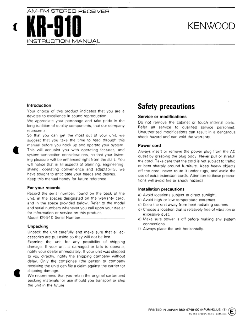
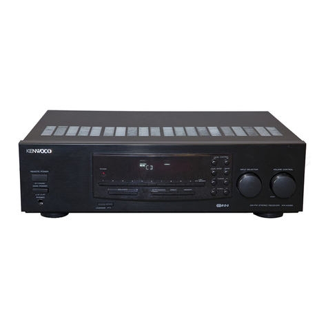
Kenwood KR-710 User manual

KENWOOD
HI/Fl
STEREO
COMPONENTS
SERVICE
MANUAL
KR-710
(KR-710L)
An
item
of
adjustment
is
written
in
three
languages
—
English,
French
and
German.
Un
article
sur
réglages
est
écrit
en
trois
langues,
Anglais,
Francais
et
Allemand.
Ein
Artikel
der
Abgleich
wird
auf
drei
Sprachen,
Englische,
Franzdsisch
und
Deutsch
geschrieben.
Photo
is
KR-710
STEREO
RECEIVER
CONTENTS
|
EXTER
NAG
VIEW
iiss
costes
ees
ten
desea
3
INFERNAL
VIEW
scccaciescncniieisiimat
y
oro
eet
4
BLOCK
&
LEVEL
DIAGRAM.............0.0..
ee
eters
4
DIAL
‘CORD
STRINGING
2
hieeiiiien
hice
are
5
PE
PA
hc
cssenn
otis
esate
ated
eens
roe
onion
5
EXPLODED
VIEW
ci
teriekcine
ened
wae
ee
6
ADJUSTMENT/REGLAGES/ABGLEICH
|...
en
7
PC
GOAR
D
oes
ee
et
14
SCHEMATIC
DIAGRAM
(KR-710)
....00.00
res
15
SPECIFICATIONS
(KR-710)
...........
cece
ccc
cece
eee
e
eee
ees
15
SCHEMATIC
DIAGRAM
(KR-710L)
.................
cece
etree
eee:
16
SPECIFICATIONS
(KR-710L)
2.0.0.0...
neee
reece
arenas
16
PARTS
UST
sci
eee
ee
ee
ie
17
Photo
is
KR-710L
_
Note:
~
Component.
and.
circuitry.
are.
‘subject
to.
modification
to
insure
best
3
operation
under
differing
|
jocal:
conditions.
‘This.
‘manual
is
based
on,
the
|
Se
(K)
standard,
and
prov
des
information:
on
regional,
circuit
modifi
catio
rough
use
of
alternate
schematic
diagrams,
and
information
¢
‘on
n
regional
;
Hoe
pen
sieeenee
bestared
eens
eoeenee
.
Seas
eg
teh
tweens
Of
20x
Pasewesesegentes
ee
SP
eR
s
ers
rerescereese
ernest
see
Tyee
ly
ot
amere
er
Se
ee
ere
eee
rr
err
ee
ee
ee
eee
ee
eee
eee
eee
ee
ORs
sesetsesevidecseenenseussessedonenanees
peg
tte
7
F,
;
:
Engisad
ween
LT
ERT
OHA
ATO
ORE
E
REESE
GERAD
HE
ES
st
teerenseesenenee
onrewne
‘ane
KR-710
EXTERNAL
VIEW
Dial
pointer
ass’y
Knob
(B21-004
1-05)
({K27-0132-04)
Dial
calibrations
(B20-0463-04)
KR-710
STEED
ECE
ES
Knob
Knob
{K23-0339-04)
(K23-0347-04)
Knob
(K27-0132-04)
Knob
(K27-0136-04
Phone
jack
Knob
Knob
(E11-0074-05)
(K23-0348-04)
(K23-0348-04)
GND
terminal
AC
out
let*
‘
(NQ8-0128-35)
(EQ3-)-
Antenna
terminal
Slide
switch*
(E20-0439-05)
{S31-)
Phono
jack
Power
cord®
Foot*
{E13-0612-05)
(E30-)
(JO2-)
Phono
jack
SP
terminal
{E13-0423-05)
{E20-0813-05)
*Refer
to
parts
list.
(P17)
PHOTO
is
KR-710.
INTERNAL
VIEW/BLOCK
&
LEVEL
DIAGRAM
Power
transformer*
Receiver
PCB
ass
'y*
Power
amp
section
(LO1-)
(X14-)
Front
end*
Power
supply
section
|
{(W02-)
Tuner
section
Power
amp
section
Phono
section
*Refer
to
parts
list.
(P17)
PHOTO
is
KR-710L.
BLOCK
&
LEVEL
DIAGRAM
ET
type.
Ceramic
‘te
LPF
FM
Y
iz
C2
Ct
1C2
aT
TUNING
CIRCUIT
er:
peer
(FT
am
Q—
Z8
a8
Le
C3
L4
am
ww
I
|
ats
fee
as
Zz
ee
PHONO
AM
>
TAPE
B
TAPEA
HIGH
FIL
LouNess
VOLUME
BALANCE
coe
aKERS
Prono
@
S198
-O-81+-
01
WOO
-#-#
C5,
6
$1
$2
3
5
6
OCt«SS
$7
—rec
©
5
$
S
—
[
LPLAY
@
TAPE
|
r—
REC
C
Leay
@
©
I4.9V/8N
39.948
2.35mV
DIAL
CORD
STRINGING
/REPAIR
DIAL
CORD
STRINGING
Tie
the
dial
cord
to
the
dial
spring.
Set
the
dial
pulley
as
illustrated.
Hook
the
dial
spring
on
the
boss
A.
oh
ee
starting
from
its
lower
side.
2)
starting
from
its
upper
side.
8.
Tie
the
end
of
the
dial
cord
to
the
dial
spring.
9.
Remove
the
dial
spring
from
the
boss
A.
_
Receive
a
90
MHz
signal,
and
then
mount
the
dial
pointer
at
the
90
MHz
position
of
the
dial
calibrations.
POWER
TRANSISTOR
REPLACEMENT
Mica
plate
Inslating
bushing
{F29-0030-00)
Hexagon
bolt
(NO9-0298-08)
Dress
the
dial
cord
in
the
direction
1
through
4.
Wind
the
dial
cord
two
turns
around
the
dial
shaft
_
Dress
the
dial
cord
in
the
direction
5
to
6.
7.
Wind
the
dial
cord
two
turns
around
the
dial
pulley
Boss
A
Dial
spring
EXPLODED
VIEW
M318
(Bre—Tap)
M3x14
(@r—Tap}
M4356
tf
—
Tap}
M3x8
(Or—
Tap)
’
M318
{6r—Tep)
+4
Refer
to
Parts
List
on
page
17.
iG
x
6
(F-Tap}
:-N88-3006-46
:
x
8
-N30-3008-46
M3
x
8
(Bi-Tap)
BLK
:N89-3008-45
W3x%8
(Bi~Tap?
BLK
M3xe
(8r—-Tap)
M3
x
8
(8r-Tap)
M3
x
14
(Br-Tap)
M3
x
20
43x78
(Or
~Tap)
M38
J
i6r—Tap)}
KR-710
:N87-3008-46
M48
(Br-Tap})
§:N87-4008-46
:-N87-3014-46
:N30-3020-46
KR-7
100
ADJUSTMENT
(TUNER)
oe
TEST
EQUIPMENTS
RECEIVER
OUTPUT
ADJUSTMENT
SSO
ee
CONNECTION
SETTING
SETTING
|
INDICATOR
POINTS
DISCRIMI-
95
MHz
FM-MONO
95
MHz
“
penn
ditto
1
kHz,
+75
kHz
Dev
ditto
ae
L7
OV
60 dB
(ANT
input)
DISCRIMI-
Minimum
El
NATOR
(3)
ce
Frequency
EM-
counter
to
the
junction
of
76
kHz
VCO
ditto
AUTO/MUTE
R22
and
VRS
VRQ
+200
Hz
95
MHz
via
an
AC
voltmeter
*3
95
MHz
1
kHz,
+68.25
kHz
Dev
PA
reas
7
T1
Minimum
IFT
©
eres
ag
R
(Front
end)
distortion
60
dB
(ANT
input)
SEPARA-
. . .
F
1
O00
kHz
AM
Maximum
folm
|
@
|
400
Hz,
30%
Mod
1
000
kHz
TRACKING
.
600
kHz
AM
.
|
TRACKING
re
1
400
kHz
AM
TC1,
2
sae
(2)
400
Hz.
30%
Mod
1
400
kHz
(Front
end)
1
000
kHz
MW
Maximum
MW
.
600
kHz
MW
.
Gece
ditto
400
Hz,
30%
Mod
600
kHz
ditto
MW
.
1
400
kHz
MW
|
lo
ee
400
Hz,
30% Mod
1
400
kHz
ditto
LW
.
160
kHz
LW
1
asia
400
Hz,
30%
Mod
160
kHz
ditto
95
MHz
O
Dev
60
dB
{ANT
input)
Bar
antenna
(A)
12
ditto
TC1,
2
(Front
end)
aio
Bar
antenna
(B)
L1
LW
|
340
kHz
LW
:
*1~4:
See
page
10.
ditto
REGLAGES
(TUNER)
REMARQUES
|
ss
APPAREILLAGE
ALIGNEMENT
!rRaccorp-
SECTION
MF
DISCRIMI-
95
MHz
FM-MONO
|
NATEUR
(1)
1
kHz.
+75
kHz
Dév
95
MHz
95
MHz
Spat
idem
1
kHz,
+75
kHz
Dév
60 dB
(Entrée
ANT)
DISCRIMI-
Distorsion
Relier
un
OSCIELA-
|
95
MHz
EM:
ae
sepa
76
kHz
TEUR
idem
0
Dév
AUTO/MUTE
|
“\
Bone
VRQ
Reeatrs
76
kHz
6O
dB
(Entrée
ANT)
a
voltmétre
CA.
*3
TFi
©
(+6.75
kHz
Dév)
60 dB
(Entrée
ANT)
Deel
ee
ee
SELECTION:
Lou
R
Signal
pilote
T1
Distorsion
(Partie
frontale)
minimale
SECTION
MA
(KR-710)
[ole
|
© |
wih
2
[wenn]
om
|
wate
|
atte
|
om
|
we
[an
wre
ate
Late
Ra
=
SECTION
MA
(KR-710L)
TFI
1
000
kHz
MW
Déviation
400
Hz.
30%
Mod
1
000
kHz
maximale
MW-
600
kHz
Antenne
MA
ALIGNEMENT|
‘e™
400
Hz,
30%
Mod
(A),
L2
MW.
oe
1
400
kHz
Mw
ae
TCi2>
aca
ALIGNEMENT
400
Hz,
30%
Mod
1
400
kHz
(Partie
frontale)
Sg
LW-
ae
160
kHz
LW
Antenne
MA
spans
ALIGNEMENT
400
Hz,
30%
Mod
160
kHz
(B),
L1
LW-
.
340
kHz
LW
|
*
1~4:
Voir
la
page
10.
idem
idem
KR-7
101
ABGLEICH
(EMPFANGER)
STEUR-
ABGLEICH
|
PRUFEINRICHTUNG
=
GERAT
AUSGANGS.-
EINSTELL-
BEMER-
EINSTEL-
ANZEIGE
PUNKT
KUNGEN
ANSCHLUSSE
EINSTELLUNG
LUNG
UKW-EMPFANGSABTEILUNG
DISCRIMI-
95
MHz
FM-MONO
NATOR
(1)
1
kHz,
+75
kHz
Hub
95
MHz
95
MHz
DISKRIMI-
1
kHz,
+75
kHz
Hub
dito
WZ
NATOR
(2)
60
dB
(Eingangs-
R6
signalpegel)
DISKRIMI-
2
Minimaler
ee)
NATOR
(3)
eo
Klirrfaktor
Frequenzzahier
zum
Kreuzungs-
SPANNUNGS-
ante
FM-
punkt
von
ne
GEREGELTER
dito
+
AUTO/MUTE
R22
und
VR9
VRQ
60 dB
(Eingangs-
uber
einew
+4
00
OSZILLATOR
signalpegel)
Wechsel
spann-
ungsmesser
*3
1
kHz,
+68,25
kHz
Hub
Wahler:
Loder
R
Pilotton:
(+6.75
kHz
Hub)
60 dB
(Eingangs-
signalpegel)
Minimaler
Klirrfaktor
STEREO
KANAL
*4
TRENNUNG
MW-EMPFANGS
ABTEILUNG
(KR-710}
1
000
kHz
AM
Marimaler
le
:
a
600
kHz
AM
dito
L1,2
(1)
400
Hz,
30% Mod
600
kHz
‘
(2)
400
Hz.
30%
Mod
1
400
kHz
.
(Frontende)
MW
UND
LW
-
EMPFANGSABTEILUNG
(KR-710L)
1
O00
kHz
MW
a
|
MW
F
600
kHz
400
Hz.
30%
Mod
erritantenna
(A)
L2
TCT
2
(Frontende)
Ferritantenna
(B)
ans
L1
*
1~4:
Sehen
den
page
11.
EMPFANGS-
BEREICH
(1)
MWw-
EMPFANGS-
BEREICH
(2)
LW-
EMPFANGS-
BEREICH
(1)
LW-
EMPFANGS-
BEREICH
(2)
dito
dito
600
kHz
1
400
kHz
400
Hz,
30%
Mod
MW
1
400
kHz
dito
160
kHz
400
Hz,
30%
Mod
LW
160
kHz
340
kHz
400
Hz,
30%
Mod
LW
340
kHz
KR-7
1011)
ADJUSTMENT
(TUNER)/REGLAGES
(TUNER)/ABGLEICH
(EMPFANGER)
*
4
*
4
Minimum
output
Adjust
the
tuning
knob
so
that
the
same
on
Nice
A
compromise
adjustment
may
be
required
if
left-to-right
and
amount
of
noise
is
observed
at
the
top
and
right-to-left
separations
are
unequal.
bottom
of
the
output
waveform
with
a
weak
|
*
5
FM
fronted
signal.
The
FM
front
end
section
is
completely
adjusted
in
the
*2
factory
and
further
adjustment
is
not
necessary.
When
the
Connect
the
DC
voltmeter
across
R6.
FM
front
end
section
cannot
be
repaired
by
replacing
semiconductors,
replace
the
FM
front
end
PCB
ass'y
and
do
the
following.
(1)
Set
FM-SG
to
90
MHz,
1
kHz
Mod,
+75
kHz
Dev,
60
dB
and
connect
it
to
the
antenna
terminal
of
the
receiver.
(2)
Receive
the
FM-SG
signal.
Ole
Veale:
(3)
Fix
the
dial
pointer
at
90
MHz.
*
3
*
4
*
4
Sortie
minimale
Ajuster
le
bouton
d’accord
de
facon
que
la
Ses
Beit
Si
la
sortie
la
droit
de
diaphonie
et
la
gauche
ne
sont
cieest
méme
quantité
du
bruit
puisse
étre
observe
pas
méme
regler
le
potentiometre
ajustable
pour
que
la
ten-
au
sommet
et
en
bas
de
la
forme
donde
de
sion
de
sortie
est
méme.
sortie
sous
des
conditions
d’alimentation
de
*§
signal
faible.
Si
la
partie
frontale
FM
ne
peut
pas
étre
réparée
en
rempla-
WZ
cant
les
semi-conducteurs
PCB
de
la
partie
frontale
et
effec-
Relier
un
voltmétre
de
C.C.
sur
R6.
tuer
les
opérations
suivantes:
(1)
Régler
FM-SG
a
90
MHz,
1
kHz
Mod,
+75
kHz,
60
dB
et
le
connecter
ala
borne
d’antenne
du
récepteur.
=
(2)
Recevoir
le
signal
FM-SG.
(3)
Fixer
l'aiguille
du
cadran
a
90
MHz.
Voltmétre
de
C.C.
*3
VR9
Compteur
de
frequence
A
la
terre
©
TP
|
-
ao
R22
10
ADJUSTMENT
(AMP)/REGLAGES
(AMPLI)/ABGLEICH
(VERSTARKER)
*
4
Den
Abstimmknopf
so
einstellen,
daf&
an
der
SS
Cerause!
oberen
und
unteren
Grenze
der
Ausgangswel-
lenform
bei
schwachem
Signal
dasselbe
Gerausch
auftritt.
*
2
Einen
Gleickspannungs
messer
uber
R6
anschlieBen.
Gleichspannungsmesser
*
4
Minimaler
Ausschliag
Wenn
dem
Ubersprechanteil
des
linken
Kanals
in
den
rech-
ten
Kanal
und
dem
Ubersprechanteil
des
rechten
Kanals
in
den
linken
Kanal
ungleich
sind,
eine
kompromifabgleichung
wird
geforden.
*
5
UKW-Frontende
Das
UKW-Frontende
wird
bereits
im
Werk
vollstandig
einge-
stellt.
Weitere
Einstellung
ist
daher
nicht
notig.
Wenn
das
UKW-Frontende
durch
Auswechsein
der
Halbleiter
nicht
repariert
werden
kann,
ist
die
Leiterplatte
des
Fronten-
des
auszuwechseln
und
folgende
Einstellung
vorzunehmen:
(1)
Den
UKW-Signalgenerator
auf
90
MHz,
1
kHz
Modula-
tion
+75
kHz
Hub,
und
60
dB
einstellen
und
mit
der
An-
“3
tennenklemme
des
Steuergerats
verbinden.
(2)
Den
Steuergerats
so
einstellen,
da&®
das
Mefsendersi-
gnal
empfangen
wird,
wahrend
der
Skalenzeiger
auf
90
MHz
zeigt.
OFFSET
IDLE
CURRENT
1.
Set
the
SPEAKERS
switch
to
A
and
the
VOLUME
to
0.
2.
Connect
a
DC
voltmeter
to
the
SPEAKERS
A
terminals.
3.
Adjust
VR5
(VR6)
for
a
OV
reading
of
the
DC
voltmeter.
DECALAGE
(OFFSET)
1.
Régler
SPEAKERS
interrupteur
au
A
et
VOLUME
au
0.
2.
Brancher
le
voltmétre
de
C.C.
aux
bornes
de
sortie
(SPEAKERS
A)
+
et
—.
|
3.
Régler
VR5
(VR6)
de
facn
a
ce
que
!e
voltmétre
de
C.C.
indique
OV.
VERSCHIEBUNG
1.
Den
Schalter
SPEAKERS
auf
A
und
den
VOLUME
auf
O
einstellen.
2.
Einen
Gleichspannungsmesser
an
die
Klemmen
SPEAKERS
A
anschliefen.
|
3.
Den
VR5
(VR6)
so
regulieren,
da
die
Gleichspannungs-
messer-Ablesung
OV
ist.
1.
Set
the
VOLUME
to
0.
2.
Connect
the
DC
voltmeter
between
the
emitters
of
Q27
and
Q29
(Q28
and
Q30).
3.
Adjust
VR7
(VR8)
for
a
30
mV
reading
of
the
DC
voltmeter.
COURANT
DE
POLARISATION
1.
Régler
VOLUME
au
0.
2.
Brancher
le
voltmétre
de
C.C.
sur
l'émitteur
de
Q27
et
Q29
(Q28
et
Q30).
3.
Régler
VR7
(VR8)
de
facon
a
ce
que
le
voltmétre
de
C.C.
indique
30
mV.
LEERLAUFSTROM
1.
Den
VOLUME
auf
O
einstellen.
2.
Den
Gleichspannungsmesser
zwischen
den
_
Emitter
von
Q27
und
Emitter
von
Q29
(Q28
und
Q30).
3.
Den
VR7
(VR8)
so
regulieren,
da&
die
Gleichspan-
nungsmesser-Ablesung
30
mV
ist.
DC
voltmeter
Voltmétre
de
C.C.
Gleichspannungsmesser
11
KR-7
1001)
ADJUSTMENT
(REGLAGE,
ABGLEICH}
TEST
INSTRUMENT
Oscilloscope
..........
AM
signal
generator
FM
signal
generator
Audio
generator
.....
AC
voltmeter..........
FM
multiplex
genera
Frequency
counter..
Distortion
meter
VR7
IDLE
12
ee
ee
ee
ee
ee
ee
ee
ee
ey
ee
Ppeoreneen
see
erenrarenenee
10
cok
cndeeesint
oar
eaeaearnrerteeetr
eer
eure
DC
voltmeter...........
etee
net
err
ar
eves
rane
sene
ee
ae
neennaeane
nn
een
e
rere
reece
Dummy
antenna......
LA
APPREILLAGE
PRUFINSTRUMENTE
Oscilloscope
..........
eee
Stan:
OSZINOSKOP
oie
na
diriedwcinsbraananensets
SCOPE
~Générateur
MA
000...
cccceececeeeeerereees
MWeSingnalgenerator
....................
AM-SG
Générateur
MF................
cc
cecec
cece
ee
ees
UKW-Signalgenerator.....................
FM-SG
Générateur
audio
fréquences
...........
NF-Signalgenerator
..............0.0.00008.
AG
VolltMe6tre
CA
a
ceiiccsss
cutis
muisccres
Wechselspannungsmesser
..............
SSVM
Générateur
multiplex
stéréo.............
UKW-Multiplexgenerator
................
FM-MPX
Fr6QuencelmMetre
............cccccecceeeaeu
ees
Frequenzzahler
Voltmoetre
CC
oie
oat
eden
Gleichspannungsmesser
DistOrsiOMetre
.............cccece
cece cece
eee
Klirrfaktormesser
PANTCMNG
TIGUVE
x6
boos
tier
ave
eacicetiwnnicares
Antennennachbildung
Dummy
antenna
AC
voltmeter
L8
L112
TC2
TC1
L7
TC3
|7T1
L13
vRE
Li1
|
L14]L4
OFFSET
—
VR5
VR10
VRQ
OFFSET
SEPARATION
VCO
CF3
Scope
PHOTO
iS
KR-710L
AR
71000
TUNER
(X14-121x-xx)
PC
BOARD
SPEAKERS
DOIN
CONNECTOR
DISCRI
Ov
COUNTER
76KHz
OOD
e«
POWER
TRANS
bet
AR
ABODE
ESN
AE
SAEPER
SELLER,
{OLE
30mv
C2~4
Jt2
J
t0
Jf
O7~13,
16~26
9VIMONO)
OVIAUTO)
~V.d
Far
a
SiTUN
EQ
23Vi-—Al
.
PEAKER
S
R
HEAD
PHONE
——
i
BALANCE
043
034
036
038
040
042
leo
Refer
to
the
schematic
diagram
for
the
values
of
resistors
and
capacitors.
ve
Foil
side
views
are
shown
for
PC
boards
with
the
reversed
letters.
14
QKENWOOD"
_
~____
STEREO
RECEIVER
|
D
|
ee
|
F
|
a
ee
a
2SA733
HA1457W
2SA992
|
Sp
ay
apne
ee
aes
ae
ee
ea
a
ae
cn
ee
ees
Be
ee
2SC945
ne
ve
er
2SB647
9
=,
as
330
ber
eev|
oe
aye
en
ak
i
9
|
2SC1845
RB)
aa
cha
ls
f
ocaw
#-);*
ca
r
'
2SD667
;
:
ie?
r,
|
s
ts
c
ie
/
+
+
“
e
vu
Spree
ere
tae
a
ear
>
SS
i
—_J
—]
(ese)
B
yi}
¢
zy
gl
ses
34
Nice
:
€
Cc
/
/
és
ae.
es:
/
/
a
ee
ae
au
aFC1¢8
6v!
$.6v
5
8
sa
eres
R28
226
To
“Ts
-
23
eve
TUMED)
02
-23vI-
oF
aT
:
Beiter
ge
2
ee
ver")
pSV}
2SB690
AN6551
:
;
S
eg
NY
2SD0726
PveTUNED
W.BVIDETUNED:
6vITUNED)
OVIDE
TUNED?
\
6VITUNED:
OviDE
TUNED)
\
O6
ee
a22
|
|
a
Ge
.
©
94viT
ED:
ee
uae
-
geal
tae
wad
ign
~
=
rp
C+)
bath
un
Qs
Q20
3
:
me
4
ct
—_
}
A
tO)
x
8
oF
'
3
33"
¢
Sov
z
ane
x
O43
|
af.
|
i
‘
1)
Ws
ais
C18
é
”
Ovi
TUNED)
AIS
+
py
d)
=
6VDETUNED
=
pe
eae
,
Tren
F
avian)
/
>)
3
1
ee
fi)
.
”
=
2
£8.)
7
|e
3
>
|
@
4
oe
:
2SK55
FS7812C
if2
(7
:
2SK105
SYNCRONTING
«
DITEC
TOR
3
-
wy
®
a
:
2
cre
|
°
@
S
out
.
‘all
DG
1°
3
th.
oT
2
85
cao
on
RPS"220
IN
GND
+
*
“fe
mt
R73
10K
avarice
&S
tem
C42
047
ats
3+;
6
cos
oF
J:
.
if
3
Hl
oy
tau
$
Q43
/ ;
REY
;OK
%
Ane
=
AW
LMC
-
WtAUuTo
.7v
(a
HA1137W
HA1196
pao
ee
—
HA1197
|
SS
|
3.3
90v
|
ICs
C4q
227
|
Q1,3,5~7,0~14,37,38,40,41
5
1
2S$C94KP)
Q2
7
25K103(0)
|
0
4,0,17~20,39
1
2SA733(P)
Qt5,16
-2$A79B8(G)
Q21~
24,
35,36,42,43
|
25C
18458)
Q25,26
:
2SA992C)
cr02
0047
C103
0047
Q
27,26
:
2$0667(C)
Q29,30
25864
7IC)
Q31,32
/2$8
690K)
Q33,34
:
280
2c)
-
2
|
1C4
/MAUISTW
1C2
[MAII96
|
|
Ics
“MAIO?
j
1Ca
:AN65S1
|
——+
|
1C5,6
_MAsaS7W
aaa
cr
[FS
7e12¢
|
ae
Gee
eae
Di~4a
-yosc-2
|
ee
ee
D5<?
-wo6Bs-2
Sees
eee
De
HZ
1SL
H
Oo~t2
:4Z
98
=
013-10
1S2076
|
{|
——————
era
|
019~26
_1N60O
:
025,26
-
11$34
|
O27,
70
/$Tv-26
0
29-31,44,48
"LN324G?.H
|
|
|
O3s2-43
"LN
Z24R.4
woo
7
OT
GER
POE
Oe
EL
St
EES
AE
ET
GON
eee
=
——eeEEETe
eee
eee
SER
GST
ee
i
eiaiaingieiemaiiedl
CRT
—————
nee
eee
lee
eee
—Eeee
CS
aaa
Se
>
Ics
0144
ics
040
1C4,6
C2
Q1,41
O2
1C4
08,8
Q3~7
Q100143
Q45~20
042,43,
21.26
0s
09~142
O13
014
$3,6
032,15
$3
$6,2
$4,7
D29~
34
oe
020,22
04—
4,16,t?
027
vRi
VR2
VRSS
VAR?,
TR
en
cate
arene
ae
Be
NR
ro
greed
ere
e
STEREO
RECEIVER
47
Sov
(10M
E
1,
2,72
R27
22K
aS
330
¥
RO
47m
HPL
Le
P
s
,
6
3
Ovicow
tec
eye
€e
or
gs,
|
ce
ssop
a6
3
6.
Dd
@vomenrtredg
qwve
TUNED)
60
2
Svitvat)
ze
Ov
wv
)
s
)
es
eso
LPL
aaa
SPECIFICATIONS
~~
-
an
:
wt
gtel
WS
al
73
———
oa
Or
wee
POWER
AMPLIFIER
SECTION
<3:
3T:
=
alt
Power
Output
I
123
*
ally
28
watts*
per
channel,
minimum
RMS
both
A
:
ae
eed
channels
driven,
at
8
ohms
from
20
Hz
to
atin
é
ii
is
ae
ee
20,000
Hz
with
no
more
than
0.08%
total
har-
3
-pywicet
‘
2
at!
at
monic
distortion.
5
eavice
toon
8
§
132
2
all
Both
Channels
Driven
ERE
a
z
;
-"
2
into
8
ohms
at
1,000
Hz..........
31W+31W
S
dca
$
L
into
4
ohms
at
1,000
Hz..........
36
W+36W
wi2
3
Total
Harmonic
Distortion
(20
Hz
to
20
kHz
from
TAPE)
sis
a
ea
Bue
a
a
:
oT:
é
rated
power
into
8
ohms..........
0.08%
“18
omy
|
'
lee
sy
|
:
e
1
W
power
into
8
ohms...........
0.04%
|
‘ie
|
:
‘
Ht
intermoduration
Distortion
(60
Hz:7
kHz
=
4:1
SMPTE)
2vTUNCG
wee
8
2g
af
FH
id
eg
:
rated
power
into
8
ohms..........
0.04%
ce
|
a
rae)
x
1
W
power
into
8
ohms...........
0.02%
OviT
UNE
O)
{
t
az:
OVIDE
TUNED)
'
s
4|
;
a
oe
eax
y
{
i
(=)
-oy
$2
gt@e)
~
|~o
fF
FPPPPHPER
gh
Rise
Then.
cece
eee
ef
'
Guise
cure
|
Lt
.
Slow
Rate...
6...
eee
eee
50
Vins
|
Q%
|
2
-j
:
Damping
Factor
.....................
45
at
1
kHz,
8
ohms
Soy
Fd
\
ars
|
-;
an
eed
ee
te
Input
Sensitivity/Impedance
i
Bn
¥
¥
I
sp
:
PHONO.
...0.
2.
cece
eee
eee
2.5
mV/50
kohms
“1
Aa
3
i
1”
2
TRPE
cist
enatenics
eiaduts
eras
150
mV/50
kohms
,
tT)
x
:
:
|
23
3
Signal
to
Noise
Ratio
(A
weighted)
:
Exe
a
$
>
Ig
°
PHONG
x.ccisis
fog
ices
Ldn
vig
nti
on
tele
78
dB
for
2.5
mV
input
:
al
-“]|
«
$
\
22
a
84
dB
for
5.0
mV
input
£35
1s
Pies
‘
12g
co
g
TAPE
on
letclari
deh
wagced
104
dB
for
150
mV
input
7
SvOETUND
Bay
Maximum
Phono
input
Level
:
savimono)
|
eg
Fy
Sato
1
58
Zz
at
1000
Hz...
eee
200
mV
(RMS),
THD
0.08%
_2ViaM)
Sie
eNO
ar
eee
a
ee
SS
ae
mire
300
Frequency
Response
Ra
aS
.
ide
PHONO
RIAA
Standard
Curve
.......
30
Hz
to
20
kHz
+0.4
dB
=
H
e
-
&
TAPE
oebisictd
enon
kien
tea
deeda
ds
7
Hz
to
200
kHz
-3
GB
‘
<"h2
°
R176
960
Tone
Control
oh3°
72
388
z
ae
Babs
ossiven
ceca
e
eae
+8
dB
at
100
Hz
«f°
Treble...
ccc
cece
cece
eas
8
dB
at
10
kHz
aes
Loudness
Control
(VOL.
-
30d8)........
+10
dB
at
100
Hz
|
High
Fitter...
ees
5
kHz,
6
dB/oct
|
8
Output
Level/impedance
|
°
é
ae
TAPE
REC
Out
(Pin)...............
150
mV/300
ohms
oo
|
5
ry)
|
Sarr
FM
TUNER
SECTION
|
:
aoe
+.
wm
Usable
Sensitivity..................8.
10.8
dBf
(1.9
»V)
|
:
ae
50
dB
Quieting
Sensitivity
a
e
ae
LEFT
RAORG
shaciciiidc
ital
tate
tateunes
17.2
GBf
(4
yV)
*F
08
en
Stes
iccaceanayersiases
Helen
37.2
dBt
(40
»V)
:
“Ss
8
Signal
to
Noise
Ratio
at
65
dBf
ir
Motiaisceze
catia
iande
nel
piu
76 dB
*Ovauta
SPEAKERS
CT
71
dB
ane
‘
7
Total
Harmonic
Distortion
PV
(MONO!
®
A
MONG!
o
cag
cio
tieles
dae
aah
0.1%
Ov
tau
¢
Qt
2
a
Stele
wei
ie
ikae
ik
teehee
0.15%
balirrrsie
(
)
*
pasar
Frequency
Response.................
30
Hz
to
15
kHz,
+1
dB,
-—2
dB
“
*
Capture
Ratio
....................05.
1.0
dB
d
--+
Image
Rejection
Ratio................
48
dB
rvIADTOr
Spurious
Response
Ratio
.............
70 dB
re
IF
Response
Ratio....................
90
dB
Alternate
Channel
Selectivity
.........
52
dB
at
400
kHz
AM
Suppression
Ratio................
50
dB
Stereo
Separation
Ratio
..............
45
dB
at
1,000
Hz
35
dB
at
50
Hz
to
10
kHz
Subcarrier
Product
Rutio..............
45
d8
Antenna
impedance..................
300
ohms
balanced
&
75
ohms
unbalanced
FM
Frequency
Range.................
B8
MHz
to
108
MHz
AM
TUNER
SECTION
Usable
Sensitivity....................
20
nV
(350
xV/m)}
Signal
to
Noise
Ratio
.................
50
d8
:
Wmage
Rejection
...................0.
40
d8
Q1,3,5~7,9~14,37,38,40,41
Solectivity
...............
0...
c
eae
45
dB
:
:
28C945(P)
:
ca
[enono]
rf
Q2
>
2$K105(H)
[sure]
ss
wono
|
go
[enone]
z.
‘
0
4,6,17~20,39
‘
2SA733(P)
GENERAL
MUTING
OFF
$
z
Q15,16
:
2$A798(G)
KENWOOD:
mIGH
SPEED
OC
SERVO
LOCK
Power
Consumption
.................
160
W
(UL
and
CSA)
=
Q21~24,35,36,42,43
|
25C1845(E)
i
;
[as
fas
fan
fos
jena
juntos
fas
jon
fun)
160
W
(8
ohms
at
rated
power)
|
Q2s,
26
:
2Sa992¢E)
24
W
INo
Signal)
6002
Coa?
C103
Cod?
oars
.
aepeaen
AC
Outlet
00...
c
ee
ec
e
eens
Switched
1,
Unswitched
1
Ps
erty
988
fan)
Dimensions
USA
and
Canada
Other
Countries
|
@
33,34
:
280
726(C)
4
HIGH
FILTER
(OUDMESS
vart
W:
458
mm
(18-1/32")
440
mm
(17-5/16")
sto
$8
se.
37
a
8
MUTING
LOCA
OF
VOL
ueet
H:
110
mm
(4-5/16”)
110
mm
(4-5/16*)
be
as
Pa
(]
(]
meres
sce
]
f
|
t
(
D:
298
mm(11-23/32")
298
mm
(11-23/32")
2
HAI
orr
SOURCE
Weight
ics
HANST
eass
TREBLE
Bac
ancé
:
|
ies
ANena;
@
ms
(Net)
7.5
kg
(16.5
Ib)
7.2
kg
(15.9
Ib)
1C5,6
HAIGS7W
®©
@
_®.,..
KR~710
(Gross}
8.5
kg
(18.7
tb)
8.2
kg
(18.1
Ib)
iCc?7
7
FS7e12C
STEALO
RECEIVER
:
*Measured
pursuant
to
Federal
Trade
Commision’s
Trade
Regulation
rule
O1-4
:UosC-2
:
cia
2
Ds~7
‘wo6B-2
on
Power
Output
Claims
for
Amplifier
in
U.S.A.
Oe
DHZ95L
Oo~i2z
[HZ98
a
a
Dis-w
:
2076
Kenwood
follows
a
policy
of
continuous
advancements
in
development
For
this
019~24
:1N60
reason
specifications
may
be
changed
without
notice
025,26
-
51834
Peas
tae
g
tie
Seer
Sere
aS
Ozer,
ze
:STv-2h
:
Kenwood
strebt
stancige
Verbasserungen
in
der
Entwicklung
an
Daher
bieiben
O
29~31,44,48
>
LN3246?P.n
Anderungen
der
tecnnischen
Daten
jederse:t
vorbehalten
|
032~43
[LN224RP.H
ea
ee
SP
a
hpi
e
Ss
wee
wee
ee
te
ee
ey
—eeeee
ret
ee
Ee
ES
eC
a
aS
TS
se
36g
meres
ee
oe
——eee
et
soe
ae
oe
eee
Kenwood
poursuit
une
politique
de
progrés
constants
en
ce
qui
concerne
le
.
developpement
Pour
cette
raisun
les
specifications
sont
sujettes
a
modifications
Sans
preavis
Ne,
.
-
<<
-
eee
oe
ee
ee
es
ee
eco
coe
1C4,6
1C2
Q1,41
G2
14
08,8
Q3~7
Q10013
Q18~20
042,43,
21.26
O27034
C7
O37~39
035,36
Oe~
93
Ova
$3.6
032
15
23
$8,2
$4.7
529~
31
rT)
020,22
01~41647
O27,20
03,6
O16
$11
023~26
OF
$109
O33~e
045
~40
VR
VR2
VRS6
VR7,8
VRS
VRE
DC
voltages
are
measured
by
a
VOM
of
20
kQ/V
input
impedance.
a
2SA733
2SA992
2SC945
2SB647
2SC1845
2S0667
2SB690
2SD726
2SK55
2SK68
2SK105
HA1137W
HA1196
HA1197
16
HA1457W
AN6551
FS7812C
a
gems
ne
armen
QOKENWOOD'
STEREO
RECEIVER
zm
TUNER
(X14-1210
-10)
FRONT
END
(WO2
Am
ean
ant
S
“
g
Qa
|
8
]
|
3
my
=
|
«
Lehi
(@
PHONO
a
L____—-
Reh
mien
REC
Ren
TAPE
B
r—Lech
PLAY
t—Reh
ra
ich
5
REC
L—
Reh
TAPE
A
ra
len
PLAY
L—
Ren
_*
.
4
°
ea
n"
CIN
REC
SP
a
€.
Ete
ONY
B
-0051-08)
Qt
2SK55
1C4:SC4114
«011182236
R2P
22K
Seer
Geena
=
ae
tincite
Me
s.
i
Tae
ee
Seal
Bt
ee
a
ete
Lf
wg
3
Sova
ow
trey
eye
5
Bv>tegntrea
;
ae
wi
2
aaa
x
RE
15K
MHOSCRIRG
Q«4
R28
22%
XS
23
eve
TUNED!
c2svean
Q2
Ov
(TUNED)
6
2v(DE
TUNED?
Cit
O47
Ro
SiGMar
2VITUNED!
W.GvICE
TUNEL”
VITUNEDD
Ov(DE
TUNED)
x
ee
‘2
2
gaviT
NEO)
6
@
OVOET
NED)
:
a
2
z
x
«
=
3
53
RI?
47K
e
=
«
8
<
ut
i)
Qt
,
ct?
001
ct9
—
é
R16
4
Wy
”
v
sm
O
O
R223
22K
5
gees
sa
R20}
R2e
OV
(TUNED)
O
6
viOE
TUNE
DD
:
:
S.6V
(MONO)
S.ev(auToO)
2
VAM)
fr
RSS
330
oy
&
as
=
Qa
x
aa
6
°
ast
>RR.|
>
4
«
-
ja
=
na
tO]
eT?
Zz
g
+13
igs
.
€
”
0
ef”
oe.
n
“
8
an
&
1]
°
«
«
R62
470K
R72
10K
14.4
(MONO)
Ov
aura
joa
Lame
&
ORIVER
f
O
O
O
4
co
25.01
or
=
1W(MONO)
WW(AUTO
Pv
{AM}
=
————
ae)
°
|
|
|
3.3
50V
Ics
c4q
22P
|
Qs
~7,9~
‘
p
pode
Soran
seen
5
Q2
5
2$%
105
(H)
(ca)
/
0
4,8,17~20,39
‘
2SA733(P)
ov
Fo
w/
218.9v_
|
77)
tv
015,16
1
2$A798(G)
.
Q21~24,35,36,42,43
|
2$C1645¢€)
:
|
Q25,26
|
2$A902
(2)
Res
150K
mer
12K
Q27,28
:2$0687(C)
est
|
alain
Q29,30
‘2$B687(C)
C55
O22
Q31,32
298
690C)
Q33,34
-
280
726(C)
Reo seo
|g
©58
:
Q44
:2sK
ea
A
ice
[HAIN3S7W
C3
[HAIS7
.
Raa
RE
RE
1Ca
-ANGSSI
;
—
=
1€5,6
[HAIGITW
;
yee
3
cr
LFSTe2C
:
3
ae
GD
:
Di~4
:yOsc-2
earner
gees
Oe
IMZISL
,?
ae
Oan~t2
[4Z98
,
See
Bice
sao
eee
ee
ee
ee
Di9~24
:1N6O
:
|
025,26
11934
O2rT,
28
.$TV-2H
0
29~31,
44,48
“LN324GP.H
7
|
032~43
[UN
223RP.n
——
ED
GETS
«STEED
OED
gee
——
ae
—-
——————
aE
ee
eee
ee
eee
eee
eee
eee.
Oe
a
a)
O
a
EE
EE
SESE
ice
ooo
a
2
104
06,8
Qsn7
O10~15
5
Q1S~20
0
Qa2as,
21-26
_
oA
88082
NS
$3
$8,2
$4,7
CN
He
20,22
04
~
4,
16,17
DZ
vRi
vR2 VR5,6
VR?,
R27
22K
wiv
TUNED)
POS
.
“esviraes
:
ae
meat
Die
33
25v
MuUhING
Q4-
23
WO
TUNED)
23svie
sn
R20
22K
OviTUNED)
6
2v(DE
TUNED)
—_———
Ovi
Tune
D)
3.B
VIDE
TUNED)
SIGNAL
2
Vi
TUNE
DO}
WE
VIDE
TUNEL)
6V(
TUNED}
OviDt
TUNED)
OV
(TUNED)
Ovidt
TUNED)
]
x
«
2
sawing
oF
is
@OV@e
Tyne
oO!
>
-
«
2
e
&
un
“|
“Na
ee
x
f
RIG
4
'8
Ah
a
O
O
gx
¢
33K
4
50v
z
ag
3
«
« «
cree
QC
eis
TL
|
R15
+
oe
4
ad
ev
CT
INE
DY
a
©
oviot
TUNE
°
i
SOV
MOO)
-
.
$.6v(
AUTO)
an
7]
ry
a
o
«
.2¥(aM)/
~
F
=
26
©
Dy
ad
°
“Sx
x
8
°
2
a
=
x
> +
r4
°
«
-
baad
9
Pa
ot
°
o
oT
399
g
2
>
°
23x
a
?
=
bd
+
°o
4
=z
2e
3°
”
a
«
«7
3
me,
“
Rat
aA
&
Se
ae
|
Z
?
v
|
8
|
3
|
”
|
£
rv
°
OVI
TOUCH)
«
19K
Mz
2
O°
|
|
3
1G
9VIF
MD
Sty
|
at
5
:
Qa
8
Ff
|
ba
5
Gabe,
Cee
ead)
2
R62
470K
Tt
dvi
MONOD
OWL
AUTO
1t4
ViAM)
Ccroo
Oo
470
25v
C125
.01
\
~.1V
MOND}
2.
WiAUTO)
\7¥
AM)
Q1,3,5~7,9%13,37,38,40,41,45
:
2$C945(P)
Q2
+
2$K105(H)
Q
4,8,17~20,39
!
2SA733(P)
Q15,16
284798
(G)
Q21~
24,
35,36,42,43
|
25C1045(E)
|
Q25,26
prebta
Q
27,28
:
28D667(C
asia
iatreina?
abi
Q29,30
:
2$B647(C)
er
Ven
Q34,32
:
2SB690(C)
Q33,34
280
726(C)
-{.
§j¢
Q44
:
25K68
238
338
tole
1C4
“HAII37W
-
_
@acfil
Mo»
q
1C2
SHALI9G
etx
.
ots
[ies
‘HANST
535
pi
Ib]
ee
ay
Bs
|
|
1C4
1
ANGSS1
1C5,6
>
HAI457W
bed)
3
|
1c?
FS7e12C
$
O1na
[uOSC-2
z
O5<7
:wO06)-2
as
a
a
|
De
DMZESL
frien
Ficten)
se
(ceuoness)s7
oie
ssoie
|
D19~24
:1N60
025,26
°1934
027,28
:STV-2H
SSS
—
O29~31,44,48
>
LN324GP.H
|
D32~43
TLN224RP.H
=
PEALE
ca
mmemmentnetiedl
Domrtiiateedecteet
aoc
ak
re
cal
PRE
OEE
22S
lel
ES
PO
TOATASEOPE
ita
niaaleniiiciel
REE
eT
an
altaiomeial
|
nena
eae
()
ee
SE
OOS
SES
i
onteemnennennedl
[a
Sieh
Tne
ee
0
a
02
164
08,0
snr
NS
«ABN
20
042,43,2—26
AFA
ee
-
ny)
ee
_
om
$86
O32
18
SS
SOR
oe
a
ee
OE
8
Ss
O20,
22
inden?
Cer
28).
SS
eh
eee
oe
ahaa
amt
ep ak
eS
cg
a
ee
nn
ae
a
ee
ct
VRt
VR2
Saenea
ee
carr
co
ee
eg
eee
Ua
ere
eisai
1...
pavnene
t/a
SS
|
ee
0
45:R€D)
des
160
OO
RiS3S
12K
270
240
220
R+tGS
RIES
RiG7
MES
HT:
rn
82,
vR3-0
SOKIC)
100
:
+
a7
63V
RISS
10K
R138
+>
x
aiao
VR3-8
SOKtc)
C83
VR4-p
SOKIC)
O47
160
220
240
RITZ
AITO
RIGH
RIEE
RIES
HIGHFILTER
LOUONESS
se
37
TUNING
ON
OFF
016
S11
0
23~26
046
\EO)
srerco
ia
eo
POWER
LEVEL
a
€
”
a
#8
a
om)
@
wf
lI>
alil3
*
lis
can
wu
z
¢
a
R175
$60
‘yaw
R176
560
‘sew
al
:
+,
Gwen
A
el
LEFT
a
-A
SPEAKERS
HIGH
SPEED
OC
SEAVO
LOCK
POWERLEVELIW/ON)
_&
98
9
08
00000
@
coromDes
»
Ho
®
TAPE
SELECTOR
tW
Sw
FM
AUTOFMMONO
PHOND
MUTING
LOCK
OFF
VOLUME
=OT0G0)
©
LEFT
RIGHT
KR-7T1OL
STEREO
RECEIVER
DC
voltages
are
measured
by
a
VOM
of
20
k2/V
input
impedance.
SPECIFICATIONS
AUDIO
SECTION
Rated
Power
Output
8
ohms
at
20
Hz
to
20
kHz
no
more
than
0.08%
THDIFYC).......................
28
W+28
W
4
ohms
at
63
Hz
to
12.5
kHz
no
more
than
0.7%
THO
IIEC)...
ee
40
W+40W
Total
Harmonic
Distortion
Rated
Power
Output
into
8
ohms...
6...
eee
0.08%
intermodulation
Distortion
©0006...
eee
0.04%
Frequency
Response
...........0
06.6
ccc
eee
ees
7
Hz
~
200
kHz
+0dB,
-3d8
S/N
Weighted:
Rated
Output
Power
(IEC-A)
( )
=
Unweighted
at
50
mW
(DIN}
PHONO!
coc
i
ee
eee
a
ie
ea
ee
ae
78
dB
(56
dB)
WARES
eo
osicks
B00
Seed
Alisa
eda
Meee
ea
Snes
104
dB
(60
aB)
Damping
Factor
at
8
ohms,
1
kHz
.............
Aids
fA
ora
tener
45
Transient
Response
Rise
TiO
icici
eco
bees
Ck
eae
nae
ea
ee
ea
ee
1.5
ys
Slew
Rate
0
cee
erent
terete
enees
+50
Vius
input
Sensitivity/impedance
PHONO:
6
ip
oh
eae
ad
Pak
ee
OS
Be
i
ee
2.5
mV/50
kf
TAPE
iss
ios
cS
ce
re
bberk
oie
Ectaa
anata
kee
Be
150
mv/50
kf
Tone
Control
Bass
TOO
Mei.
lie
ee
hikes
oie
eh
a
ie
des
+8
dB
Treble
10
kHz...
eee
Sapna
tae
needa
den
+808
Loudness
Control
(—30
dB)
.....................00005.
100
Hz,
+
10
dB
High
Filtet
icici
big
eee
et
wk
ae Oh
ee
ed
Sat
5
kHz,
6
dB/oct.
FM
TUNER
SECTION
Sensitivity
at
75
ohms
Mono:
S/N
26
dB,
40
kHz
Dev...
6.0
cee
1.2
4V
Stereo:
SIN
46
dB,
46
kHzDev.
0.6...
eee
30
«Vv
50
dB
Quieting
Sensitivity
Mono
(IHF)...
6...
ee
eee
4uVv
Limiting
Level
~
3
dB
Point.
40
kHz
Dev...
eee
nes
1.0
4V
Frequency
Response
....
10...
eee
30
Hz
~
15
kHz
:
+1
dB,
-2
08
Totat
Harmonic
Distortion
Mono:
1
kHz,
40
kHz
Dev.
600...
0.1%
Stereo:
1
kHz,
46
kHz
Dev.
0...
eee
0.2%
S/N
Weighted
(iEC-A)
Mono:
40
kHz
Dev.,
}
mV
Input...
eee
72 48
Stereo:
46
kHz
Dev.,
1
mVinput
..0..
eee
68
dB
S/N
Ratio
(IHF)
.
Mono:
75
kHz
Dev..
1
mV
Input...
ee
76
dB
Stereo:
75
kHz
Dev.,
}
MVinput......
0.
eee
71
4B
FM
Stereo
Separation:
1
mV
Input
(DIN)
260)
Wbe
oi
nled
de
leaden
beaks
head
Bat
ea
Sica
amore:
35
dB
WWM
ees
sc
Ss
ree
beldiod
dene
Beeteta
4
die
tees
Yew
es oe
40
dB
Oi
D
MME?
keh
ai
Sewanee,
Mee
Sb
AD
wana
adaees
30
68
V2S
Ma
ok
a
hae
tee
A
oh
eae
betas
see
24
dB
Image
Rejection
Ratio
ees
48
48
Selectivity
300
kHz,
20
dBinput..
6.6666
eee
55
dB
IF
Rejection
Ratio
600.
eee
90
aB
AM
Suppression
Ratio...
6...
es
50
dB
Spurious
Response
Ratio
......
6...
eee
75
dB
Capture
Ratio...
0.
eee
e
tens
1.0
dB
Pilot
Tone
19
kHz.
ccc
cee
eee
Be
pate
uiees
45
0B
MW
TUNER
SECTION
SensitivityS/N20
dB...
eee
20
wV
(350
pV/m)
SIN
Ratio:
1
MV
input...
ee
50
aB
Image
Rejection
Ratio
......
6.6.2
40
dB
LW
TUNER
SECTION
SensitivityS/N
20
dB.......
eee
16
wV
(350
wV/m)
S/N
Ratio:
1]
mV
input............
Alia
das
GALL
See
else.
te
9
-temern
date
doen
of
50
dB
Image
Rejection
Ratio
......
6...
een.
ephase-
4
deste
40
dB
GENERAL
Power
Consumption
Rated
Powerat8
ohms.........
tee
was
oe
Santos
as
160
W
Nosignal.
3...
ee
ibe
joadenetle
heptane
tail
2M
Dimensions...
ee
W
840
mm
H
110mm
0.
298
mm
Weight
(Net)...
Bein
wack
ez
tynd
avd
teat
A
md
eked
se
ong aoe
aa
Reg
Kenwood
follows
a
policy
of
continuous
advancements
in
development
For
ths
feason
specifications
may
be
changed
without
notice
Kenwood
strebt
standige
Verbesserungen
in
der
Entwicklung
an
Oaher
bleiben
Anderungen
der
technischen
Daten
jederze:t
vorbehalten
Kenwood
poursuit
une
politique
de
progrés
constants
en
ce
qui
concerne
le
devetoppement
Pour
cette
rasan
les
specificanrons
sont
sujettes
a
modifications
Sans
preavis
PARTS
LIST
Refer
to
exploded
view
on
page
6.
INSTRUCTION
FOR
PARTS
LIST
Description
A01e0608412
A2CoIG7F
ON
A2Co197G=11
aeCot97Gell
A2CeI97I=11
METALLIC
CABINET
FRONT
PANEL
ASSY
FRONT
PANEL
ASSY
FRONT
PANEL
ASSY
|
FRONT
PANEL
ASSY
el
——
——s
6)
R&3o1333~15
|
FLePROCE
80330
3
2k
RESoI1S6BONS
FLePROOF
RO68BO
Jon
e
ipt2e3304"05
|
TRIMMING
POT,
20K(8)
RIG
46305005
A12e2302205
POTENTIOMETER
(OUTPUT)
TRIMMING
POT,
5K(B)
’
Exploded
vrew
drawing
No.
Position
in
exploded
view.
»
Symbol
of
new
parts.
Area
to
which
parts
are
shipped.
Example:
A20-1390-13
is
the
part
No.
of
FRONT
PANEL
ASS’Y
for
the
K”
type
products
(for
USA).
When
this
column
is
blank.
it
means
that
the
same
type
of
parts
(same
parts
No.)
are
used
for
the
products
shipped
to
all
areas.
§
Reference
No.
in
schematic
diagram.
‘Abbreviation
of
“ceramic
Capacitor’.
All
capacitors
and
resistors
are
listed
using
abbreviations.
Abbreviations.
*
Abbreviations
of
capacitors
(Parts
No.
with
initial
letter
‘s)
(wa)
(9)
(OF)
te
ELECTRO.............
Electrolytic
Capacitor
LL-ELEC
........
.....
Low
leak
electrolytic
Capacitor
NP
EEC
athe
tte.
Non-pole
electrolytic
Capacitor
MICA
2.0...
Mica
capacitor
POLYSTY.............
Polystyrene
Capacitor
MYLAR
...............
Mylar
capacitor
CERAMIC............
Ceramic
Capacitor
TANTAL
..............
Tantalum
capacitor
1
aR
ee
ne
ee
Metallized
film
capacitor
NUP
io
esosnacsteeenihaues
Metallized
paper
capacitor
Olle
ccart
eis!
Oil
Capacitor
The
unit
“UF”
is
used
in
leu
of
“pF”
*
Abbreviations
of
resistors
(Parts
No.
with
initial
lerrers
“R’).
RC
ates
pecan
auaids
Carbon
composition
resistor
BO
iaat
ccocccen
canes
aioe
Carbon
film
resistor
FL-PROOF
RD.....
Flame-proof
carbon
film
resistor
a.
ee
ee
ern
Wire
wound
power
resistor
FL-PROOF
RS
.....
Flame-proof
metal
oxide
film
resistor
RN...
.................
Metal
film
resistor
FUSE-RESIST
......
Resistor
with
fuse
function
2B.
__..................
Rated
wattage
1/8W
QE
....................
Rated
wattage
1/4W
2H....................
Rated
wattage
1/2W
3A.
....................
Rated
wattage
TW
BD
edie
teaiaerwas
Rated
wattage
2WwW
see
.............
Rated
wattage
SW
3G.....................
Rated
wattage
aw
3H
.
Rated
wattage
5W
Atl
resistor
values
are
indicated
with
the
unit
(2)
omitted.
*
Abbreviations
Common
to
Capacitors
and
resistors.
C...
.
..,
£0.25pF
(Used
for
capacitors
only)
DO
veten
.
+0.5pF
(Used
for
capacitors
onty}
Foo.
6
cakes
spe
8g
TN
Goce
veces
ccessssees
£2%
CI).
oa:
gxesnasdetieaniye
Eaaeneee
+5%
Kn
vees
wales
ace:
+10%
een,
adietaastaaskitss
+20%
Zin
cist,
Biyesnsvaisonnes
+
80%,
—
20%(Used
for
capaciters
only)
P
+
100%,
—0%(Used
for
capacitors
only)
Resistors
RD
(carbon
composition
resistors)
are
not
listed
in
the
parts
list.
For
values,
refer
to
the
schematic
diagram.
Codes
in
X14-121*-**
K,P
=
X14-1210-10
T
:
X14-1210-51
T
:
X14-1210-51
T.
©
X14-1210-52
KR-710L
KX
:
X14-1210-71
E
=
X14-1212-71
UM
:
X14-1210-81
E,
©
X14-1212-72
KR-710L
Ref.
No.
SORES
|
8
2
EF
HF
14
SA
14
3A
15°
3A
C146
C146
C176
C116
61164117
16
28
17
28
18
2a
19
2A
20)
618
20
«618
20
«618
21
1B
22
18
22
18
22
#18
22
«618
22.
«1B
Parts
No.
A01-0373-03
A01-0373-03
A01=+0374203
A01-6374-03
A01-0374=-03
A04-0374=-03
A20-1676-+08
A20=1674=-08
A20-1674=08
A20-1674+08
A20-167¢=08
A2C=167E=03
A2C-1E80-03
AS5SG-007E=03
ASC
*0078=03
A50-0079-03
A50=-007G=-03
646=0055-20
B46-006C=00
B46=-0061=20
B46=-0062=20
846=-0063-13
646-0064-10
B56-3157=+00
B50-3157-00
B50-3157-00
B50-315&=-00
250-+3159=00
650=3166=00
850-+3161-00
850-3162-00
B850-3188=-00
B50-3205-00
B20=-0463-04
B20-0473-04
821-6041-05
C91~0046-08
C91=0045=08
C91-0082=08
€91-20151-08
c91=0151-08
015-0164+04
p15-0172=04
DIS-0175-05
020-0154=03
E03-0010-08
E03-0010-08
E03-0010-08
E0460004+05
E30=-0181-05
E30-04659=05
E30=0545-05
E30-0587-05
E30-0649=05
6010004524
Description
Bh
RLM
REAR
PANEL
SUBPANEL
BOTTOM
PLATE
ANTENNA
HOLDER
CASE
CASE
CASE
CASE
CASE
CASE
KR=710L
FRONT
FRONT
FRONT
FRONT
PANEL
PANEL
PANEL
PANEL
FRONT
FRONT
FRONT
SIOE
SIDE
PANEL
PANEL
PANEL
BOARD
BOARD
BOARD
BOARD
SIDE
SIDE
WARRANTY
WARRANTY
WARRANTY
WARRANTY
WARRANTY
WARRANTY:
INSTRUCTION
INSTRUCTION
INSTRUCTION
INSTRUCTION
INSTRUCTION
INST.
L
R
R
ASSY
ASSY
ASSY
ASSY
ASSY
ASSY
KR=710L
ASSY
KR=710L
CARO
CARD
CARD
CARO
CARD
CARD
MANUAL
MANUAL
MANUAL
MANUAL
MANUAL
MANUAL
KR*7170L
INSTRUCTION
MANUAL
INST.
INST.
MANUAL
KR@770L
MANUAL
KR#=7170L
INSTRUCTION
MANUAL
DIAL
CALIBRATIONS
KR~710
DIAL
CALIBRATIONS
KR#=710L
OIAL
POINTER
ASSY
CERAMIC
CERAMIC
CERAMIC
CERAMIC
CERAMIC
DIAL
PULLEY
O.01UF
O.01UF
0.01UF
O.O01UF
OQ.07UF
125VAC
SMALL
PULLEY
X4
SMALL
PULLEY
DIAL
SHAFT
AC
OUTLET
AC
OUTLET
AC
OUTLET
COAXIAL
CONNECTOR
POWER
CORD
POWER
POWER
POWER
POWER
CORD
CORD
CORD
CORD
TENSION
SPRING
KR-/
101)
Ref.
No.
Parts
No.
SOmES
8
BF
SF
H01-3166=-08
H01"3167=-08
HO01=3168-08
H01=-3168-08
HO01=-3169=-08
HO01-3170-08
HO1=3171+08
H01=+3472-08
H1021551-02
H10-1552"12
H20~0417=04
H20-0452-04
H20"0452-04
H20-0452=04
J02-0088=05
J02-0089205
£02-0089-05
J02~-0089-05
J4740034"05
J42-0084-05
142-0084205
3422008505
K22=-0339-04
K23=0347-04
K23~-0348=-64
K27-0132=04
K27-0136=04
L01-2091-08
L01-2092=08
L01=2095+08
L01-2095=08
L01-2096-08
101-2097=08
NO8=-0128=35
g31-2050-05
§31-2050-05
$40-1010-05
540=1011-05
§40-2099-05
$40-2099-C65
790
-0087-05
7902010405
T90-0202-05
x¥14=-12160=10
X1401210-10
X¥1601210-51
X14=41216-52
x146-1210-71
X14-1210-81
X16"1212-71
X14e1212+72
RECEIVER
(X14-121x-xx)
€05=-0073-<15
C24-1010-61
C2401222-71
C55-1710-38
C24-1447=57
CARTON
CARTON
CARTON
CARTON
CARTON
CARTON
CARTON
CARTON
POLYSTY
POLYSTY
POLYETH
POLYETH
POLYETH
POLYETH
FOOT
FOOT
FOOT
FOOT
POWER
C€
POWER
C€
POWER
C
POWER
C
KNCB
(T
KNOB
(V¥
KNOS
(T
KNOB
(P
KNCB6
POWER
T
POWER
T
POWER
T
POWER
T
POWER
T
POWER
T
GNO SCR
SLIDE
§$
SLIDE
S
PUSH
BU
PUSH
8U
PUSH
BU
PUSH
BU
Am
LGOP
Am
LOOP
FM
INDO
RECEIVE
RECEIVE
RECEIVE
RECEIVE
RECEIVE
RECEIVE
RECEIVE
RECEIVE
FRAME
CERAMIC
ELECTRO
ELECTRO
CERAMIC
ELECTRO
PARTS
LIST
Description
w
2/SR
HE
8OX
8OX
BOX
BOX
BOX
BOX
BOX
KRe7T0L
BOX
KR=710t
RENE
FOAMED
RENE
FOAMED
BAG
BAG
BAG
BAG
YLENE
YLENE
YLENE
YLENE
ORD
BUSHING
ORD
ORD
ORD
BUSHING
BUSHING
BUSHING
UNING)
OLUME)
ONE.
BAL)
USH)
RANSFORMER
RANSFORMER
RANSFORMER
RANSFORMER
RANSFORMER
RANSFORMER
Ew
wlTCH
($1)
wITCH
($1)
TYGN
SwITCH
TTON
SWITCH
TTON
SWITCH
TTON
SWITCH
ANTENNA
KR=7T0L
ANTENNA
KR=710
OR
aNTENNA
R
PCB
R
PCB
R
PCB
R
PCE
R
PCB
ASSY
ASSY
ASSY
ASSY
KR@710L!
|
ASSY
ASSY
ASSY
E
ASSYKR@=7104)
E2
R
PCB
R
PCB
R
PCS
TRIMMER
1OUuUF
166
220UF
16WV
O.,O1UF
Zz
4.7UF
250
eCP
KR=7T0L
Ref.
No.
FR
FS
gS
&
#
8
Parts
No.
c71-1733-16
|
CERAMIC
C24=21747-41
|
ELECTRO
€55=-1710-38
|
CERAMIC
C24~-101G"671
|
ELECTRO
C45-1747"36
|
POLYSTY
C26-1722-51
|
ELECTRO
C24-01222-71
|
ELECTRO
C24-1010-61
|
ELECTRO
C46-1710=25
|
POLYSTY
646=+17106-25
|
POLYSTY
C46"1715—-25
|
POLYSTY
C€4621715-25
|
POLYSTY
C25-1710-57
|
LL=ELEC
€46-17467=35
|
POLYSTY
C48-21736"15
|
POLYSTY
62521715957
|
LL-ELEC
C24-1633-51
|
ELECTRO
C2521722-47
|
LLmELEC
C24-1747941
|
ELECTRO
C55=+1710-28
|
CERAMIC
655=21710=38
|
CERAMIC
C71+1710-02
|
CERAMIC
C€94-90003-400
|
CERAMIC
€55+1716-38
|
CERAMIC
C24-1210-71
|
ELECTRO
C7041716-02
|
CERAMIC
€25-1710957
|
LU“ELEC
C71-1708202
|
CERAMIC
€71-1747"05
|
CERAMIC
C$5e1710-38
|
CERAMIC
C25~"1710957
|
LL-ELEC
C24-101C-61
|
ELECTRO
655-1710-28
|
CERAMIC
C55-1710938
|
CERAMIC
C91-0003"-00
|
CERAMIC
C4641747"35
|
POLYSTY
C91-0003200
|
CERAMIC
C71=-1722-05
|
CERAMIC
C2501733-57
|
LL-ELEC
C71-171C"15
|
CERAMIC
C24-0810-79
|
ELECTRO
C71-1710215
|
CERAMIC
C46-1722°35
|
POLYSTY
649-2062-24
|
POLYSTY
C24-1433-51
|
ELECTRO
C24e1433e71
|
ELECTRO
C25"1733-57
|
LLeELEC
C74121710"15
|
CERAMIC
C71"1733-16
|
CERAMIC
C24=1010+61
|
ELECTRO
C25=-1710<57
|LL-ELEC
C€24-1433951
|
ELECTRO
€7101747205
|
CERAMIC
C2401710971
|
ELECTRO
C712-1715"06
|
CERAMIC
C46=-1710-45
|
POLYSTY
C24=1447-51
|
ELECTRO
C26-1710°57
|
NP-ELEC
C2521710"47
|
LL=ELEC
€4621718-35
|
POLYSTY
C71-1710"02
C52=1782<16
CERAMIC
CERAMIC
820PF
Description
BA
A/SR
HE
S3OPF
0.47UF
O.O1UF
10UF
0.047UF
2.2UF
220UF
10UF
O,001UF
O,O0C1UF
0.001SUF
0.0015UF
TUF
0.047UF
360PF
1.5UF
3.3UF
O.22uUrF
O.470UF
O,O0TUF
O.O1UF
10PF
0,0TUF
0.01uUF
100UF
10PF
1UF
8PF
47PF
O.01UF
1UF
1OUF
O,001UF
O,01UF
0.,01UF
0.047UF
O.01UF
22PF
3,3UF
100PF
100UF
100PF
0,022uUF
0.0062UF
3,
3UF
S30UF
3.3uUF
TOOPF
330PF
1OUF
TUF
3,3UF
47PF
TOOUF
TSpF
O.1UF
4.,7uF
TUF
O.1UF
0.0178UF
TOPF
zZ
DKR=710
25WV
zZ
16%V
D
50wV
DKR=710
17
Ref.
No.
Parts
No.
ORES
|
8
BE
F
C94
495
C96
497
099
€100,101
¢102,103
C98
€104,105
C107,108
C109-110
C111
Ciie
C143
C114
€1145
C117
C118
C119=421
C122
C123
C4124
C125
€434,135
C4136-138
161
162
103
104
105
18
18
2A
2B
28
28
2A
C7191722015
64601747435
C46-1710435
C24=1047-61
C46—1747"25
64601787935
690-0492-08
65442710929
C24-144771
C24-1410=81
C26-1433-71
C€2421433-61
C24-21710-61
C25-1710-57
C24-1010-61
C4624747=35
C48-473
6-15
C47=-1712-15
C71=21727=06
C€54-2710-29
C4601
74725
C€55=-1710-38
€£06+#0513=05
E14-0074<05
E13-+0423-05
£13-0612=-05
E20=-0439-05
E20-+0813-05
FOS-2023-05
FO5=2029=05
F06-2027=05
FOS-3022=05
FOS=3122=205
F06-3023-05
FO5-15217-05
FO5-1622-05
J13=0055-05
£19-20569=04
J19=-0570=03
L72=0057=15
L72-0057=15
L72-0059=205
L72-0078=-05
L31-0457-05
L3220242-05
L32-0244-05
L30-0329205
L30-0284+05
L40-1021-13
L40-2292-13
L30-0316-05
L30-0317=-05
£33~+0282-08
L79=-0072+05
L79=-0109205
L79=0074-05
L32-02466=05
L4Q-2292-=13
L40-2292-13
L40-2292-13
PARTS
LIST
Description
CERAMIC
220PF
POLYSTY
0.047UF
POLYSTY
O.O1UF
ELECTRO
470UF
POLYSTY
0.00467UF
POLYSTY
0.018UF
ELECTRO
6800uF
CERAMIC
O.O1UF
ELECTRO
470UF
ELECTRO
1000UF
25wV
25wy
25wWV
25WV
SOWV
SOwvV
16WV
ELECTRO
S30QUF
ELECTRO
33uF
ELECTRO
10uUF
ELECTRO
1UF
ELECTRO
10uUF
POLYSTY
0.047UF
KKR=7108
POLYSTy
360PF
JKR710LET
POLYSTY
120PF
J
CERAMIC
27PF
KKR=770L
CERAMIC
O.OTUF
PKRe710L
POLYSTY
O.O0047UF
4
CERAMIC
O.OTUF
2
DIN
CONNECTOR
PHONE
JACK
PHONO
JACK
(4P)
PHONO
JACK
(6P)
ANT
TERMINAL
SPEAKER
TERMINAL
FUSE(2A)
FUSE
(2A)
FUSE
(2A)
FUSE
(3a)
FUSE(3.15A)
FUSE
(3A)
FUSEC1.5A)
FUSE(1.6A)
FUSE
CLrP
LED
HOLDER
LED
HOLDER
CERAMIC
FILTER
CERAMIC
FILTER
CERAMIC
FILTER
CERAMIC
FILTER
AM
ANT
COIL
KR#=710
Lw
OSC
COIL
KR=770L
AM
OSC
COIL
KR=710
AM
IFT
AM
IFT
INDUCTOR
INDUCTOR
FM
DET
COIL
Fm
OET
COIL
INDUCTOR
LPF
BBF
Lw
LPF
KR*71G6L
Mw
OSC
COIL
KRe710L
INDUCTOR
KR=710
INDUCTOR
KR#710
INDUCTOR
KR#710
Description
Ref.
No.
Parts
No.
mR
&
8&8
©
#&
R1
R43—21210415
|
FL=PROOF
RD100
J
2€
R14
R43=-1256-05
|
FLePROOF
RD56
J
ee
R93
496
R47-15392915
|]
FL=PROOF
RS390
J
3A
R111
R43e1318=25
|
FL=PROOF
RO1,8K
J
2H
R11541146
R43"e1215°15
|
FL=PROOF
RD15O
J
2€
R4119,720
R43e1210215
|
FL=PROGE
RD100
J
R121
R43~71256"05
|
FLePROOF
ROSS
J
2€
R1254126
R43=21210-15
|
FL=PROOF
RD100
J
2€E
R127-130
R43=1233-415
|
FL=PROOF
&D330
3
2E
R131-2134
R9200110+05
|
CEMENT
0,47
K
3A
R135,136
R47=-5547295
|
FL@PROOF
RS4,7
J
3:
R1441,142
R40-8316-05
|
Rc
16
J
2H
R15941760
R40-8310-15
|
RC
100
Jed
R175,176
R42=27256°15
|
RC
560
J
2H
R186
R43e01222205
|
FLePROOF
RDZ2
J
2€
R188
R47"¢5512215
|}
FLePROOF
RS120
J
30
R193
R40-8347"56
|
RC
4.7M
kK
2H
R193
R40-8347-56
|
RC
4,7M
K
2H
R193
R92=-0173=-05
|
RC
2.2M
J
2H’
R193
R92-0234-05
|
RC
12M
J
2H
R2162217
R43~-1312°05
|
FL=PROOF
RDi2
J
2k
VR1
R06=-5055-205
|
POTENTIOMTER
(VOL.)
VR2
R05-5004=-05
|
POTENTIOMTER
(BAL.)
VR3
44
R10-4005"05
|
POTENTIOMTER
(TONE)
76
R12-3005=-05
|
TRIMMING
POT.
COFFSET)
76
78
R12=-30460-05
R12-0081-08
R12-3002=05
R12=3041-05
R12-507805
TRIMMING
POT.
COFFSET)
TRIMMING
POT.
(BIAS)
TRIMMING
POT,
(VCO)
TRIMMING
POT,
(VCO)
TRIMMING
POT,
(SEPARATE)
R12=5026205
TRIMMING
POT.
CSEPARATE)
$90-0035-05
$90-0037=05
$42-6008=05
$42-7003-05
$42-2041=08
SLIDE
SkITCH
KR=770L
REMOTE
WIRE
KR~710L
PUSHBUTTON
SWITCHKR#710L
PUSHBUTTON
SWITCH
KR=710L
PUSHBUTTON
SWITCH
$42-2035205
|
PUSHBUTTON
SWITCH
¥11=-0238=05
¥11-0295=05
¥11-2104=-80
v¥11"#2104=40
V11—"90271805
udsc
wWO6B
HZ15L
H298
152076
v11-0051-05
¥V11=+7761-590
V17-5100+80
¥V11#1100"+20
¥11-1100430
1N6Q
1834
STVe2Hw
LED
(LN324GP,H)
GREEN
LED
CLANZ224RP,H)
RED
V1721100=20
¥11*20271=05
V3C-0133-05
V3020155"05
¥30-0196=05
LEO
(LN324GP,H)
GREEN
1§2076
KR=71T0L
HAT137W
HA1196
HA1197
AN6551
HA1457w
FS7812C
250945
(P)
2SK105(CH)
V30-0353-10
V30-02646-10
1V¥30-9693+10
VO3B=0405"05
V09"0127=-50
V03-0405-05
V01-0213=05
V03-0405-05
V04#0213-=05
28C945(P)
2SA733(P)
250945
(Pp)
2§A733(P)

Other manuals for KR-710

2

This manual suits for next models

1

Other Kenwood Stereo Receiver manuals

Kenwood VR-8060 User manual

Kenwood

Kenwood VR-8060 User manual

Kenwood KRF-V4060D User manual

Kenwood

Kenwood KRF-V4060D User manual

Kenwood KRF-V7070D User manual

Kenwood

Kenwood KRF-V7070D User manual

Kenwood VRS-6100 User manual

Kenwood

Kenwood VRS-6100 User manual

Kenwood VRS-N8100 - AV / Digital Multimedia Receiver User manual

Kenwood

Kenwood VRS-N8100 - AV / Digital Multimedia Receiver User manual

Kenwood KRF-V8080D User manual

Kenwood

Kenwood KRF-V8080D User manual

Kenwood 107VR User manual

Kenwood

Kenwood 107VR User manual

Kenwood Eleven III KR-1000 III User manual

Kenwood

Kenwood Eleven III KR-1000 III User manual

Kenwood KRF-X9090D User manual

Kenwood

Kenwood KRF-X9090D User manual

Kenwood KR-V5560 User manual

Kenwood

Kenwood KR-V5560 User manual

Kenwood KR-6170 User manual

Kenwood

Kenwood KR-6170 User manual

Kenwood 1090VR User manual

Kenwood

Kenwood 1090VR User manual

Kenwood KR-V77R User manual

Kenwood

Kenwood KR-V77R User manual

Kenwood KR-794 User manual

Kenwood

Kenwood KR-794 User manual

Kenwood KR-A4040 User manual

Kenwood

Kenwood KR-A4040 User manual

Kenwood AR-304 User manual

Kenwood

Kenwood AR-304 User manual

Kenwood KR-V5570 User manual

Kenwood

Kenwood KR-V5570 User manual

Kenwood KR-V6040 User manual

Kenwood

Kenwood KR-V6040 User manual

Kenwood KR-300HT User manual

Kenwood

Kenwood KR-300HT User manual

Kenwood KR-V8070 User manual

Kenwood

Kenwood KR-V8070 User manual

Kenwood CT-201/KXF-W1010 User manual

Kenwood

Kenwood CT-201/KXF-W1010 User manual

Kenwood KR-300HT User manual

Kenwood

Kenwood KR-300HT User manual

Kenwood KRF-V6070D User manual

Kenwood

Kenwood KRF-V6070D User manual

Kenwood KR-A57R User manual

Kenwood

Kenwood KR-A57R User manual

Popular Stereo Receiver manuals by other brands

Aiwa CUD-N858 Service manual

Aiwa

Aiwa CUD-N858 Service manual

Marantz 4270 user manual

Marantz

Marantz 4270 user manual

Denon DRA-800H Service manual

Denon

Denon DRA-800H Service manual

Marantz NR1506 quick start guide

Marantz

Marantz NR1506 quick start guide

Technics SA-5570 operating instructions

Technics

Technics SA-5570 operating instructions

Yamaha RX-V383BL owner's manual

Yamaha

Yamaha RX-V383BL owner's manual

Outlaw RR 2150 owner's manual

Outlaw

Outlaw RR 2150 owner's manual

JVC RX-D302BC instructions

JVC

JVC RX-D302BC instructions

Pioneer VSX-D603S operating instructions

Pioneer

Pioneer VSX-D603S operating instructions

Yamaha DSP-AX757SE owner's manual

Yamaha

Yamaha DSP-AX757SE owner's manual

Sony STR-DN1050 Updating the software

Sony

Sony STR-DN1050 Updating the software

Sony STR-D565 Service manual

Sony

Sony STR-D565 Service manual

Tecsun PL - 118 Operation manuals

Tecsun

Tecsun PL - 118 Operation manuals

Sangean DPR-34 Plus Operating	 instruction

Sangean

Sangean DPR-34 Plus Operating instruction

Pioneer SX-202 manual

Pioneer

Pioneer SX-202 manual

Marantz SR5008 Getting started

Marantz

Marantz SR5008 Getting started

Denon DRA-F109 Getting started guide

Denon

Denon DRA-F109 Getting started guide

Pioneer XR-P160 operating instructions

Pioneer

Pioneer XR-P160 operating instructions

manuals.online logo
manuals.online logoBrands
  • About & Mission
  • Contact us
  • Privacy Policy
  • Terms and Conditions

Copyright 2025 Manuals.Online. All Rights Reserved.