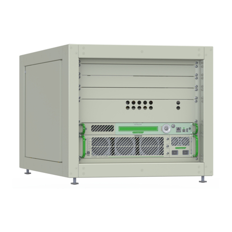
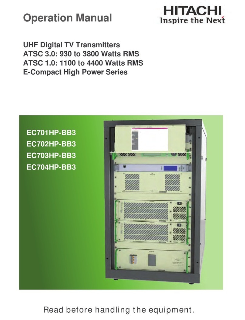
Hitachi EC702HP User manual

W AR N I N G
All rights reserved. No part of this manual may be reproduced or transmitted in any
form, by any means (electronic, photocopying, recording or otherwise) without the prior
permission of the publisher, except where permitted by law.

Hitachi Kokusai LinearEquipamentosEletrônicosS/A
TECHNICAL ASSISTANCE
In our Quality Management System, since several devices are received without proper identification and explanations; we
are now working with previous approval for maintenance devolution.
Therefore, in case of maintenance please contact:
Hitachi Kokusai Linear Equipamentos Eletrônicos S/A
Phone: (+35) 3473-3473 / Fax: (+35) 3473-3474 E-mail: manutencao@linear.com.br
And inform: Client Name, Equipment Part Number, Serial Number and a brief explanation of the occurrence.
With this intel we shall send the ARM number (Authorization for Return of Material), which is mandatory to appear in the
invoice.
WARRANTY
1. All equipment shall have warranty coverage of the supplier against manufacturing or assembly faults conducted by the
supplier, for the period of 12 months, counting from the issuing of the sales invoice. The period is irrevocable except in cases
of extended warranty previously noted in contract.
2. During warranty time, the supplier will repair, with noadditional charge, thefaulty products, providing adjustments, replacing
or re-manufacturing, of all the equipment or its modules and components that present unusual behavior;
2.1. The repaired/replaced products are covered for an additional period of 3 (three) months or uptothe end of the original
warranty time, taking into count the longer period;
2.2. If the additional 3 (three) months term, referred above, is higher than the original warranty term, the warranty will only
extend to the repaired/replaced modules or components;
2.3. The warranty will become effective in the supplier’s factory, therefore it’s not a responsibility of the supplier: the
shipment of any modules, components or any other equipment or accessory. These expenses will be, when due, a
responsibility of the Purchaser.
2.4. The Purchaser may choose a visit of the supplier’s technical personnel , instead of submitting the goods for factory
repair, although the expenses relative to transportation, lodge and nourishment of the supplier’s technicians will occur at
sole expense of the Purchaser, upon budget approval.
3. The supplier is relieved of the warranty terms in the here in aftersituations:
3.1. Faults or defects caused by AC Mains variation, atmospheric phenomena or accidental;
3.2. Faults or defects caused by inadequate installation of the goods, not complying with the OPERATING MANUAL(S)
or caused by negligence of the minimum infrastructure requirements in the installation site, which is referred in the ANNEX
1 herein attached.
3.3. Faults or defects caused by inadequate usage of the products, not complying with the OPERATING MANUAL(S) or
by lack of proper preventive maintenance recommended in the product’s manual.
3.4. In event of the goods and its accessories are submitted to 3rd Party maintenance, unauthorized by the supplier, as
well as removal or violation of its serial number.
4. The supplier shall employ, during warranty term, original parts and components listed by the product’s manufacturer.
5. The technical assistance must be held by the SUPPLIER or its accredited personnel or companies, failing which will result
in warranty voidance.

Hitachi Kokusai LinearEquipamentosEletrônicosS/A
WARNING
MANDATORY CONDITIONS FOR
TRANSMITTER INSTALATION, FOR
VALIDATING THE WARRANTYTERMS
1. Propergrounding;
2. Properlightning-rod;
3. Shelter with ventilation, foot-print, and
temperature in compliance with thetransmitter’s
standards.
4. Voltage regulator in compliance withtransmitter’s
consumption.
Noncompliance with any of above-mentioned terms
will automatically result in the suspension of the
warranty terms.

Hitachi Kokusai LinearEquipamentosEletrônicosS/A
ANNEX I
TOPIC
MINIMUM INFRASTRUCTURE REQUIREMENTS
AC MAINS
GROUNDING
The grounding system,to which Hitachi Kokusai Linear’ TV transmitter will be attached, mustbe designed andimplementedby trainedprofessionals. An
improper groundingsystemmayputatrisk, notjust theequipmentbutthelife of theprofessionals working in the shelter. To beconsideredproper, the
groundingmusthavearesistanceof nomorethan5
STABILITY
Itis importantto haveisolation between energystationsof theshelter and theTV transmitter, which is achieved with the usage of isolator transformers.
Thus is guaranteed that noAC Mains’ transient comingfrom theshelter will be passedonto the TV transmitter or vice-versa. Besides, Hitachi Kokusai
Linear’ TV transmitterfeaturesswitching powersupplies thatrequire purely sinusoidalpower input,and voltage regulators or no-breakswithout isolator
transformers havenoassurance of a purely sinusoidal outputs. The isolator transformer must also be exclusive to the TV transmitter andits dimensioning
mustuse the same standards employedin the dimensioningof the voltageregulator or no-break, ie, atleast 30%higher than the TV transmitter’s specified
consumption(inKVA).
INSULATION
Itis importantto haveisolation between energystationsof theshelter and theTV transmitter, which is achieved with the usage of isolator transformers.
Thus is guaranteed that noAC Mains’ transient comingfrom theshelter will be passedonto the TV transmitter or vice-versa. Besides, Hitachi Kokusai
Linear’ TV transmitterfeaturesswitching powersupplies thatrequire purely sinusoidalpower input,and voltage regulators or no-breakswithout isolator
transformers havenoassurance of a purely sinusoidal outputs. The isolator transformer must also be exclusive to the TV transmitter andits dimensioning
mustuse the same standards employedin the dimensioningof the voltageregulator or no-break, ie, atleast 30%higher than the TV transmitter’s specified
consumption(inKVA).
WIRE GAUGE
EC701HP
EC702HP
EC703HP
EC704HP
EC706HP
EC708HP
2.8 kVA
5.5kVA
8.3kVA
11kVA
16.5kVA
22kVA
Current
Gauge
(mm2)
Current
Gauge
(mm2)
Current
Gauge
(mm2)
Current
Gauge
(mm2)
Current
Gauge
(mm2)
Current
Gauge
(mm2)
M220
P+N+G
1 phase with neutral : 220Vac between phase and neutral
13
1.5
25
6
38
10
50
16
75
35
100
50
B220
2P+G
2 phases, without neutral: 220Vac between phases
13
1.5
25
6
38
10
50
16
75
35
100
50
T220
3P+G
3 phases, without neutral: 220Vac between phases
13
1.5
23
4
23
4
34
10
45
10
68
25
T380
3P+N+G
3 phases with neutral: 380Vac between phases, 220Vac
between phase and neutral
13
1.5
13
1.5
13
1.5
26
6
26
6
39
10
(*) (*) (*)
(*) Due to the number of amplifiers not bemultiple of 3, the current is not equal to the3 phases (unbalanced system).
The current quoted in the table is more loaded phase to sizing effect of conductors and protection.
Said gauge is theminimum recommended for the transmitter in question, if the cable length is large, consider voltagedrop in the cablemaximum of 5%
The section of the neutral conductor should be the same phase.
The section of the ground conductor may be 10% of the phase conductors, not being less than1mm2.
The settings on the green background with table arethe recommended settings for eachtransmitter model.
ADPS
LIGHTNING ROD
The Atmospheric Discharge Protection System –ADPS is comprised by thelightning rod and its accessories. The tower and shelter mustbe protected
againstAtmospheric Discharges, througha FRANKLIN lightning rod, dimensioned andinstalled by the USER, following the criteria definedby NBR 5419
(inits latestversion) and includingall thestation installations within theprotection zonedefinedintheLevelI electro-geometric modelof rolling spheres.
PROTECTORS
The usage of coaxialprotectorsis advisablefor cables which connectinternal and external equipments (antennas, microwave heads, tower converters).
These shields are devicesfeaturinggas-sparklers thatshort-circuit to theground, any surges dischargedin thecoaxialcables. Must bewithin the shelter,
closetothe equipmentandwithits ground wire boundintheequipment’s rack ground.
CLIMATE CONTROL
TEMPERATURE
For bestperformanceand longer lifetime of theequipment,it is importantthatthe shelter featuresa strictclimatecontrol, through theinstallation of anair-
conditioning system. For project purposes, consider the thermaldissipation specified to the transmitter (BTU/h), the thermaldissipation of theother devices
in theshelter, the thermalchargecause by solar incidence and all other thermalcharges within theshelter. It is recommended thattheinternalpressure of
the shelter is slightly positive, avoiding the entranceof outsidecontaminants. According to thetransmission power, the internal temperatureof theshelter
shouldbe:
•LOW POWER E-COMPACT TV TRANSMITTERS: from 0 to 35ºC
•MEDIUM POWER E-COMPACT TV TRANSMITTERS: from 0 to 30ºC
•HIGH POWER E-COMPACT TV TRANSMITTERS: from 0 to25ºC
In theeventof damagecausedby inefficient or improper Climate Control Systems within theshelter, will automatically result in the suspensionof the
warranty terms.
HUMIDITY
The relative humidity within theshelter is a solely importantfactor for best performance and longer lifetime of the equipment. Hitachi Kokusai Linear’
devices mustoperatein dry environments; this is also achieved by proper Climate Control Systems. In accordance with transmission power, therelative
humidity mustbe:
•LOW POWER E-COMPACT TV TRANSMITTERS: from 0 to 90%
•HIGH POWER ANDMEDIUM POWER E-COMPACT TV TRANSMITTERS: from 0 to 80%
Should never be condensation, as water may damage internal circuitry of the transmitter.

1
Section 1 - Introduction
Indice
Section 3 - Installation
1.1 Purpose ofthisManual ................................................1-1
1.2 Basic Knowledge Required .........................................1-1
1.3 Structure..................................................................................1-1
1.4 GeneralDescription.....................................................1-2
1.4.1 Transmitter’s Control System ..........................1-3
1.4.2 E-Compact ATSC Transmitters Models...........1-6
1.4.3 Composition.....................................................1-6
1.4.4 Block Diagram of the System...........................1-7
1.4.5 Functional Description of the System..............1-8
1.4.5.1 ATSC Digital Exciter.............................1-8
1.4.5.2 Coaxial Relay (Optional Dual Excitation)
............................................................................... 1-14
3.1
Introduction .......................................................3-1
3.2 Inspection..........................................................3-1
3.3 Installation Recommendations ..........................3-1
3.3.1 PreventiveProtection .............................3-1
3.3.2 Tower..............................................................3-2
3.3.3 Fastening of cables, antennas and
connectors........................................................3-2
3.3.4 Equipment Installation Indoors ..............3-4
3.3.5 Equipment Grounding........................... 3-4
3.3.6 Electric Installation Grounding ...............3-5
3.3.7 PowerSupply.........................................3-5
3.4 Mechanical Drawings ........................................3-6
1.4.5.10 Electrical Distribution Drawer (MCCB)
.............................................................................. 1-19
1.4.5.11 Cooling System...................................1-19
1.5 Technical Specification - E-Compact TV ATSC
Transmitters .....................................................1-20
1.6 Photo - EC702HP Tansmitter................................1-21
Section 2 - Minimum Installation
Requirements
2.1 Introduction..................................................................2-1
2.2 Minimum Requirements...............................................2-1
2.2.1 Electric Power....................................................2-1
2.2.1.1 Grounding .......................................................2-1
2.2.1.2 Stability......................................................................2-1
2.2.1.3 Insulation........................................................2-2
2.2.1.4 WireGage ......................................................2-4
2.3 Atmospheric Discharge Protection System .................2-4
2.3.1 LightningArresters ............................................2-4
2.3.2 CableProtectors................................................2-5
2.4 Air Conditioning............................................................2-5
2.4.1 Temperature...............................................................2-5
2.4.2 Humidity............................................................2-5
2.4.3 Cooling............................................................. 2-6
3.5.2 PowerDrawer.......................................3-14
3.5.3 Rejection Loads Drawer ....................... 3-16
3.5.4 AC UnitPanel........................................ 3-17
3.5.5 TopPanel...............................................3-18
3.6 Power Network Connections............................ 3-19
3.6.1 Power Feeding Options ........................3-19
3.6.2 AC Power Cable Connections.............3-19
3.7 UNPACKING..............................................................3-23
3.8 ONSITE PHYSICALASSEMBLY ..................... 3-33
3.8.1 Assembly Instructions........................... 3-33
3.8.2 Connections ......................................... 3-35
3.8.2.1 Internal Connections.............................3-35
3.8.2.2 External Connections............................3-42
Section 4 - Initial Activation
4.1 Introduction .......................................................4-1
4.2 Connections and Final Checks .........................4-9
4.3 Possible operations with the Transmitter in
Operation ..........................................................4-9
4.3.1 Communication ....................................4-9
4.3.2 Serial terminal Emulators ......................4-10
4.3.3 Forbidden operations.............................4-10
4.3.4 Safeguards .............................................4-10
4.4 Automatic Power reduction Table........................ 4-11
1.4.5.3 Power Splitter .......................................
1-14
3.4.1
Front View ............................................. 3-6
1.4.5.4 UHF Power Amplification System ....
1-14
3.4.2
Rear View......................................................3-7
1.4.5.5PowerCombiner.................................
1-17
3.4.3
Side View.......................................................3-8
1.4.5.6 Loads Bank ..........................................
1-17
3.4.4
Dimensions (mm)..................................3-9
1.4.5.7 Filtering System ...................................
1-18
3.4.5
Top view with filter........................................3-10
1.4.5.8RF SamplingProbe............................
1-18
3.5
Front
Panel.......................................................3-11
1.4.5.9PowerSupplies...................................
1-18
3.5.1
DigitalExciter.........................................3-11

2
Section 5 - System Operation Manual
5.1 Introduction............................................................. 5-1
5.1.1 FrontPanel ................................................. 5-1
5.2 Digital Exciter - The Master Control Unit ................ 5-1
5.2.1 Keypad.................................................................5-2
5.2.2 Display.................................................................. 5-2
5.2.3 Signaling............................................................... 5-2
5.3 Flowcharts Screens................................................ 5-3
5.3.1 Presentation and Main Options .................. 5-3
5.8 Remote Management System (Telesupervision) 5-47
5.8.1 IPConfiguration............................................5-47
5.8.2 Mask Configuration ......................................5-48
5.8.3 GatewayConfiguration.................................5-48
5.8.4 Host Address Configuration.........................5-48
5.9 Options....................................................................5-50
Section 6 -
5.4 Startup....................................................................5-13
5.5 Setup Menu .............................................................5-13
5.5.1 PowerSetup.................................................5-15
5.5.2 TransmitterSetup .........................................5-15
5.5.3 Image Frenquency Suppression..................5-16
5.5.4 LO Adjustment (LO Leakage Suppression)
.......................................................................... 5-18
5.5.5 Active / De-active Pre-Correction..................5-18
5.5.6 Modulation Settings......................................5-20
5.5.7 Time anddate configuration.........................5-21
5.5.8 Password .....................................................5-21
5.5.9 Transport Stream Input.................................5-22
5.5.10 AlarmsMask.................................................5-23
5.5.11 USB Setup ...................................................5-23
5.5.12 USB HostAccess Setup ...............................5-24
5.5.13 CrestFactor Reduction.................................5-24
5.5.14 Clock Reference ..........................................5-25
5.5.15 RestoreWeb Password toDefault................5-27
5.5.16 TransistorAgingAdjustment.........................5-27
5.5.17 PATemperatureControl ................................5-29
5.6 MeasurementsMenu................................................5-30
5.6.1 Power ..........................................................5-32
5.6.2 Transport Stream.................................................5-32
5.6.3 RF Power Drawer Measurements ................5-33
5.6.4 ExciterPower Supply....................................5-36
5.6.5 Communication among RF drawers.............5-36
5.6.6 Software/Hardware Version..........................5-37
5.6.7 Automatic LevelControl................................5-38
5.6.8 Clock Measurements ...................................5-39
5.6.9 Power Supply Voltages.......................................5-40
5.7 AlarmSystem.....................................................................5-40
5.7.1 CurrentAlarms..............................................5-40
5.7.2 AlarmLog.....................................................5-41
5.7.3 DrawersAlarms............................................5-42
5.7.4 ClearPastAlarms .........................................5-43
6.2.1 Cleaning.......................................................6-1
6.2.2 VisualInspection ..........................................6-2
6.2.3 Reading Verification .................................... 6-2
5.3.2
Setup Menu ...................................................
5-4
5.3.3
Measurements ............................................
5-8
Preventive Maintenance
5.3.4
System Alarms / Log ....................................
5-10
5.3.5
Remote Access ............................................
5-11
6.1
Introduction ................................................................
6-1
5.3.6
Options ...........................................................
5-12
6.2
Preventive Maintenance ..........................................
6-1

Section 1- Introduction (UHF Digital TV Transmitters)
E-Compact -Air Cooling -ATSC- High Power
Manual Rev. 0.0 - April 2016
1-1
Section 1
Introduction
1.1
Purpose of thisManual
The purpose of this manual is to provide the technical information required for the installation
and operation of transmitters in UHF TV signals (digital ATSC) in the E-Compact series.
HitachiKokusai Linear Electronic Equipment S/A recommendsthat you carefullyread thesections
of thismanual beforeinstalling or operating this equipment.
1.2
Basic Knowledge Required
Follow the necessary knowledge and skills to operate the equipment under:
•
Knowledge of electronic circuits of Radio Frequency;
•
Knowledge of electricity and electricalsystems;
•
Knowledge of digitalelectronics;
•
Conducting tests and Digital TV signals measures inATSC standard;
•
Knowledge of radiant systems;
•
Conducting tests and measures of RadioFrequency;
•
Practicein themanagement of radio frequency measures equipment (spectrum Analyzer, RF
power meter, Vector NetworkAnalyzer, couplers, attenuators, etc).
1.3
Structure
This manual is divided into seven (7) sections, which provide the following information:
Section 1 - Introduction
Thissectionprovidesgeneral overview,models, functionaldescriptionand technical specifications
for all models of transmitters ATSC of the E-Compactseries.
Section 2 - Installation Requirements
This section describes the criteria of the minimum requirements of the infrastructure for the
equipment installation, suchas: electricalpower system,lightning protection andairconditioning.
Section 3 - Installation
This section provides the procedures for physical and electrical wiring of the TV transmitter.
1

Section 1- Introduction (UHF Digital TV Transmitters)
E-Compact -Air Cooling -ATSC- High Power
Manual Rev. 0.0 - April 2016
1-2
EC701HP
EC702HP
EC703HP
EC704HP
EC706HP
EC708HP
Images for illustrative purpose
Section 4 - Initial Activation
This section describes which steps to be performed in the initial activation of the equipment.
Section 5 –Operation of the Control System
Information of navigation and Operation using the front keypad as well as identifications and
functions of all controls and indicators of the outer panel.
Section 6 –Preventive Maintenance
Provides information for preventive maintenance.
1.4
General Description
This section contains a general description of the ATSC TV transmitters of the E-Compact
series.Includedinthissectionarethefunctional descriptionof power drawers and digital exciter,
block diagrams and technical specifications of thesystem.
Figure 1-1 Front View ATSC Transmitters

Section 1- Introduction (UHF Digital TV Transmitters)
E-Compact -Air Cooling -ATSC- High Power
Manual Rev. 0.0 - April 2016
1-3
HP transmitters Family (High Power) has high efficiency and high power density.
Thehigh´s power line consists of refrigerated air transmitters with output powers of 700W up to
8.5kW (after filter) toATSCstandard.
Theintelligent digitalmanagement system usingmicrocontrollers, allowscontrol and monitoring
in real time of all transmitter functions. All operation is performed through keypad and digital
display both located on the front panel, through which we have access to all readings, alarms
and settings.
The RF amplification system iscomprises by a splitter, power drawers in parallel, each with its
own power supply and independent supervision and isolated combiner.
Main Features:
Management of all equipment functions and power drawers across the front display.
High Efficiency providing low power consumption.
Doherty amplifier technology with LDMOS HighVoltage transistors
Compact Design.
Amplifierwithquickcouplingconnection (HotSwap),facilitatinginstallation andmaintenance.
Digital automatic Pre-correction automatic (linear and nonlinear)
Control of the transmitter integrated tothe exciter.
Userinterface through display allows monitoring and configuration of the equipment.
Software for measuring measures the main parameters of the transmitter without the need
for expensive equipment and specific.
WEB and SNMP interface for remote management.
Option of automatic redundancy in excitation (optional).
GPS receiver forinternal time base(optional)
Power supplies with power factorcorrection.
Power protection reflected with gradual reduction of the direct power control (foldback).
Start withInrush.
Combiners and isolated splitters, allowing removal and insertion of drawers with the
connected equipment (provided that thedrawer isturned off).
1.4.1
Transmitter’s Control System
Control Architecture for Hitachi Kokusai Linear’ Transmitters:
HitachiKokusaiLinear’s transmitter control system allowscontrol and monitoring, through front
display, all parameters of the equipment.
Thissystemiscomprisedbyacontrolunit(exciter’s integratedfunction)whichthroughaRS485/
MODBUS network, gather and sends information tothe power drawers.

Section 1- Introduction (UHF Digital TV Transmitters)
E-Compact -Air Cooling -ATSC- High Power
Manual Rev. 0.0 - April 2016
1-4
Below the table of power drawers of addresses and exciters on MODBUS.
Table 1-1 Addresses of power drawers and Exciters - MODBUS
MODEL
MODULE
ADDRESS MODBUS (decimal)
Pinout configuration
(MSB) A2 A1 A0(LSB)
(binary)
EC701HP
PA Drawer #1
003
000
EC702HP
PA Drawer #1
003
000
PA Drawer #2
004
001
EC703HP
PA Drawer #1
003
000
PA Drawer #2
004
001
PA Drawer #3
005
010
EC704HP
PA Drawer #1
003
000
PA Drawer #2
004
001
PA Drawer #3
005
010
PA Drawer #4
006
011
EC706HP
PA Drawer #1
003
000
PA Drawer #2
004
001
PA Drawer #3
005
010
PA Drawer #4
006
011
PA Drawer #5
007
100
PA Drawer #6
008
101
EC708HP
PA Drawer #1
003
000
PA Drawer #2
004
001
PA Drawer #3
005
010
PA Drawer #4
006
011
PA Drawer #5
007
100
PA Drawer #6
008
101
PA Drawer #7
009
110
PA Drawer #8
010
111
Comum
Exciter A
100
-
Exciter B
101
-
1+1 Control
Unit
234
-

Section 1- Introduction (UHF Digital TV Transmitters)
E-Compact -Air Cooling -ATSC- High Power
Manual Rev. 0.0 - April 2016
1-5
The Architecture of Control for Hitachi Kokusai Linear Transmitters is composed of subcontrol
blocks characterized by Control / Exciter Drawers and by Power Drawer. This architecture
allows thedistribution of control functions.
The main control block represents the Control / Exciter Drawer and the sub-control blocks
represent the Power Drawers and Telesupervision Drawer (Remote Control Drawer).
Each sub-block only reports monitoring information to the main control block, and in some
situations the main control block can also transmit commands to the sub-blocks.
The Information reported to the control block is displayed on the primary display.
The control center of each block and sub-block consists of a microcontroller module of 16-bit
and 32-bit, according to its functionality described below:
a)- Main Control Module:
Themaincontrol modulereceives information from theother modules, processes thisinformation
for displaying on the LCD and sends it to the system telesupervision. The main module is also
responsible forcheckingabnormal conditions and generatealarms,control of transmittedpower
levels and general user interface. The main control module can also send commands to the
sub-blocks in situations where it is necessary to enable specific protections for sub-blocks and
also for the control of information sent and received by the remote supervision system.
b)- Power Drawer’s Control Module
Thecontrolmodulesendsinformationtothemainmoduleon request.Thismodulehas aprotection
system fully independent of the main control module. The control module is responsible for
monitoring the power supplies, the readings of forward and reflected power, cooling system,
control of quiescent current according totemperaturevariation.
Alphanumeric User Interface
The Control/Exciter drawer has a LCD display in it’s front panel companied by a keyboard with
six keys, which are: ENTER, ESC, LEFT, RIGHT, UP, DOWN. There is also closetothese keys
a set of indicative LEDs for Control/Exciter drawer alarms.
Communication between blocks and sub-blocks
The Control / Exciter Drawer uses a communication system called MODBUS. This is a serial
communication network operated by the Main Control Module in which each node (sub-block)
has its own address. This communication system works with the differential transmission
avoiding interference noise.

Section 1- Introduction (UHF Digital TV Transmitters)
E-Compact -Air Cooling -ATSC- High Power
Manual Rev. 0.0 - April 2016
1-6
1.4.2
E-Compact ATSC Transmitters Models
The E-Compact TV series consists of transmitters that have a rated power of 700Wrms to
8,500Wrms (digital). Following in Table 1-2, the available model are listed.
Table 1-2 E-Compact ATSC Transmitter Models (High Power)
TRANSMITTER
MODEL
NUMBER OF POWER
DRAWER
OUTPUT RATED POWER
(Wrms)
EC701HP
1
700
EC702HP
2
1400
EC703HP
3
2100
EC704HP
4
2900
EC706HP
6
4200
EC708HP
8
5600
EC712HP
12
8500
Note:Thepower levels are given in average power for critical mask(50dB). Thepower
ismeasured at the transmitter’s output after the filter.
1.4.3
Composition
The general structure of an E-Compact transmitter series consists of the following stages:
- Exciter with frontaldisplay
- Coaxial Relay (*1)
- Power Splitter(*2)
- Power Drawer(s)
- Power Combiner (*3)
- Reflectometer
- Filtering System
- Power System (*4)
- VentilationSystem
Notas:
(*1) Used only in equipment setup dual exciters.
(*2) The splitter is on the equipment with more than one power drawer.
(*3) The combiner is present only on devices with more than one power drawer.
(*4) The components of the AC input (In-Rush, circuit breakers, etc.) of the transmitter are contained in a
drawer called MCCB (except EC701HP model).
MCCB: Moulded Case Circuit Breaker.

Manual Rev. 0.0 -April 2016
÷
SAM PLEAFT ER FILTER P/E XC . A
SA MPLE AF TE R FILTER P/ EXC . B
RF
SAMPLING
PROBE
MODULE 40052
PASS-BAND
IN OUT
FILTER
COAXIAL
RELAY
01 x RACK EIA 19” 25U
READING + 15V OF THE MCCB
+ 8V FROM MCCB MODULE
SAMPLEAFTER
FILTER
SAMPLEBEFORE
FILTER
1,400W rms
UHF / ATSC
50EIA 1 5/8”
ASI / 310M IN 1A
(800mVpp /75 )
ASI OUT A
(800mVpp/ 75)
310M/
ASI IN
ASI OUT
ATSC DIGITAL
EXCITER
A
RFOUT
+10.8dBm
220V
DIGITAL
EX CIT ER A/B
RS485
220V
SAM PLE BEFORE FILTER P/ EXC. A
SAM PLE BEFORE FILTER P/ EXC. B
OUTPUT REFLECTED
POWER READING
OUTPUT DIRECT POWER
READING
10MHz 10MHz
REFO UT REFIN MODULE 40153
RS485
DATA BUS
…
CONTROL
I/O
ETHERNET REMOTE
+15V
FROM
MCCB
+7.35dBm UHF POWER DRAWER
RFIN RFOU T 860W
P1
MÓDULO 40001
EXC. B P1 P2
/ RJ45 CONTROL
+10.6dBm
+10.6dBm
MODULE
MODULE
OUT1
IN1
OUT2
MOD DIV 1:2
READING + 15V OF THE MCCB
+ 8V FROM MCCB MODULE
SAMPLEAFTER
FILTER
SAMPLE BEFORE
FILTER
40032 C-QS2C/2-3A
DIGITAL
EX CIT ER A/B
LOAD 1B
LOADS D RAWER
ASI / 310M IN 1B
(800mVpp /75 )
ASI OUT B
(800mVpp/ 75)
310M/
ASI IN
ASI OUT
ATSC DIGITAL
EXCITER
B
RFOUT
220V
+10.8dBm
+7.35dBm
860W
MOD COMB 2:1
C-HC40C
10MHz 10MHz
REFO UT REFIN
RS485
MODULE 40153 CONTROL
I/O
DATA BUS
…
ETHERNET REMOTE
FOR DIG ITAL
EXCITER A/B
EXC. A P1 P2
/ RJ45 CONTROL
+50V FROM
MCC B MODU LE
+15V +8V +5V +50V
THREE PHASE
220V / 380V
Figure 1-2
Block Diagram of theTransmittermodelEC702HP
LOAD 1B
MODUL E 40041
RFOUT
P2
220V
RFIN
RS485
MCCB
MODUL E 40031
IN 2
OUT
IN 1
MODULE40001
UHF POWER DRAWER
LOADS
DRAWER
Section 1-Introduction (UHF Digital TV Transmitters)
E-Compact -Air Cooling -ATSC-High Power
1.4.4 Block Diagram of the System
Figure 1-2contains the block diagram of the 1,400W transmitter, EC702HPmodel.
1-7
+8V
REFLT
IN
OUT
MODULE
40028
LOW-PASS
FILTER
MOD 40055
TO DIGITAL EXCITER A/B

Section 1- Introduction (UHF Digital TV Transmitters)
E-Compact -Air Cooling -ATSC- High Power
Manual Rev. 0.0 - April 2016
1-8
1.4.5
Functional Description of the System
1.4.5.1
ATSC Digital Exciter
The exciter is formed by the MOD GV 40153 module drawer more optional (internal GPS, and
other software optional). This equipment is responsible for generating the digital TV signal and
can perform, among other functions, for controlling the output power and the pre-correction of
distortions caused by filtering and amplification stages of a transmitter.
Has the following main modules:
1. AC-DC Converter (MOD 4779 FTE 1RU +28V/80W);
2. Ethernet/USB-Host/Deviceinterfaceboard (MODCIM3744 DIGI and USB);
3. Keyboard (MOD CIM3717 TECLADO 1U);
4. Display (MOD CIM 30165LCD 2x40);
5. MODVENP40X4024V 1U;
6. DC-DC Converter (MOD CIM 30143 PWR 8001 V4);
7. OutputAmplifier (MOD4803 PA100mW 4001);
8. MOD 4854 EXC DIGI 8001 V4 (MOD4854);
9. CIM3832 GPS 8001(Optional);
10. MOD VENP RADIAL 24V1U.
The Digital Exciter is responsible for providing an RF signal to excite the amplification stage of
the equipment.
The exciter input is a BNC connector that may receive either an ASI or SMPTE310M transport
stream. The modulation process follows ATSC A/53E recommendation, and is a complex
modulation process generating identical phase-modulated orthogonal IF carriers, (I) and (Q) at
frequencyof 18.833916MHz.
2
3
1
5
4
10
6
8
9
7
Figure1-3 -Internal View

Section 1- Introduction (UHF Digital TV Transmitters)
E-Compact -Air Cooling -ATSC- High Power
Manual Rev. 0.0 - April 2016
1-9
Both (I)and (Q)modulatedcarriers are routed intothe IF/UHF up-converter. Thelocal oscillator is
a synthesized time-based PLL via an internal VOCXO (Voltage / Temperature Oven Controlled
Crystal Oscillator). This oscillator can receive external reference one among 6 possibilities;
(External 1PPS GPS, Internal1PPS GPS,External 10MHz or InputTransportStream).
The on-channel modulated signal is routed to the RF amplifier, a class A highly linear amplifier
withenoughheadroom toaccommodatefuturesignal amplitudeexpansion duringthenon-linear
pre-correction process.
Theexciter output deliversa100mW maxRFoutputlevel,(+20dBm)at thedesiredUHF channel,
driving the RF power amplifiers line-up. The overall RF output power is kept over control via an
internal powercontrol loopALC.
The power sensors for direct and reverse power are integrated also on this same PC Board;
allow thepower control featurefor aseveral different types and models of transmitters.A sample
of the of the RF signal delivery to the load is necessary to be present, so the external loop to
control the RF power isclosed. (External Power Control Loop).
TheMaster Control Unit (MCU) of the unit is embedded in the exciter. The MCU interacts with all
functionality present within the equipment. It further interfaces externally via a keypad and an
LCD display.
The MCU receives information proceeding from several modules, as the DTV modulator, Up-
Converter, RF amplifiers, RF samples and the administration of passwords. Via keypad it is
possibletoread and program thepower level delivered by the transmitter. Major changes on the
transmitter configuration are possible with factory assistance.
TheDigital Exciter interacts withtheHITACHI proprietary software (GUI8001)that performs the
implementation of linear and non-linear pre-correction as required; the software also conducts
measurements on the demodulated signal, such as MER and power spectrum readings,
among others.
Figure 1-4
Front view - Digital Exciter
ATTENTION: In the event of any changes being required in the settings of the
equipment, the Service Department of Hitachi Kokusai Linear should be consulted
for furtherinformation on the procedures tobe adopted.

Equalizer
FPGA ASI
Output
Switch
TS BTS Integrated Reed ISDB Linear Shape Filter IF Complex Non-Linear TX DAC
Priority Remultiplexer SFN
Switch Decompressor Multiplexer Solomon Modulator Pre-correction Interpolation Mixer Pre-correction Balance Interface
Nios
SystemControl/Config. ADC
External Capture.
OCXO Control Internal Communication. Interface
1Hz PLL PLLs
SFN Delay Time
Digital Board Memories Adjust Interleaving
SRAM Memory Memory
SRAM SRAM
+28V
IF Mute
DAC _EN ABLE
Rear USB/FIFO ASIOutput
USB Rear
DAC _CL K
Rear MAC/PHY 7 IF I
FPGA
Ethernet LPF B 1:2 TEST
d
POINT
DAC 2
ASI 1 7 IF Q
ASI 1 Equalizer d TEST
LPF B
1:2
DAC_ENABLE
POINT
3
ASI 2 ASI 2 B
Sat/UHF ADC d Feedback
3
Tuner
ADC _CL K
GPS UBLOX
ant. GPS FPGA_CLK
10MHz
sysclk
PPS DAC_CLK External External External External
PPS in Schmitt SYSCLK ADC_CLK Capture Nios Nios Shared
Trigger Memories Memories Serial Serial
TEST_POINT_1 SRAM SRAM Flash Flash
Lock_Detect 1
10MHz 10 MHz
in Zero Cross 10MHz sysclk
10MHz 10MHzlo
OCXO 1:4 10MHzout Lock_Detect 1
Transmitter Voltage Lock_Detect2 Microcontroller SPI
Control. Clamp SystemControl/Config. Voltage SPI_LO
Green LPF ALC TransmitterControl/Config.. Converter
Connector UserInterface 5V/3V3
Keyboard/Display
DIGI
FPGA ASI
Output
Switch
TS BTS Integrated Reed ISDB Linear Shape Filter IF Complex Non-Linear TX DAC
Priority Remultiplexer SFN
Switch Decompressor Multiplexer Solomon Modulator Pre-correction Interpolation Mixer Pre-correction Balance Interface
Nios
SystemControl/Config. ADC
External Capture.
OCXO Control Internal Communication. Interface
1Hz PLL PLLs
Digital Board
Figure 1-5
1st Part - Block Diagram: Exciter
SPI_LO
SPI
Voltage
Converter
5V/3V3
Lock_ Dete ct 1
Lock_ Dete ct 2
10MHz sysclk
10MHz lo
10MHz out
1:4
ASI Output
IF Mute
+28V
DAC _EN ABLE
Time
Interleaving
Memory
SRAM
Delay
Adjust
Memory
SRAM
SFN
Memories
SRAM
10 MHz
Zero Cross
10MHz
in
Rear
USB
USB/FIFO
Rear
Rear
Ethernet
MAC/PHY
ASI 1
ASI 1
Equalizer
ASI 2
ASI 2
Equalizer
GPS
ant.
UBLOX
GPS
PPS in
PPS
Schmitt
Trigger
DAC _CL K
LPF
ADC
Feedback
ADC _CL K
ALC
Keyboard/Displ ay
DIGI
Transmitter
Control.
Green
Connector
IF Q
TEST
POI NT
3
DAC _EN ABLE
LPF
IF I
TEST
POI NT
2
10MHz
OCXO
Voltage
Clamp
LPF
Microcontroller
SystemControl/Config.
Tran smi tter Contro l/Con fi g..
User Interface
1:2
DAC
1:2
Section 1-Introduction (UHF Digital TV Transmitters)
E-Compact -Air Cooling -ATSC-High Power
Block Diagram -Digital Exciter
Figure 1-5contains the 1st part of the block diagram of the exciter 100mW.
7dB
7dB
Manual Rev. 0.0 -April 2016
1-10
3dB
FPGA
FPGA_CLK
External
Capture
Memories
SRAM
External
Nios
Memories
SRAM
External
Nios
Serial
Flash
External
Shared
Serial
Flash
10MHz
sysclk
DAC_CLK
SYSCLK
ADC_CLK
TEST_POINT_1
Lock_Detect 1

Up-Converter 10MHz lo Loc k_D etect2
SPI_LO LO
Local
LO LO_Q Oscillator Test_Point_4
SPI_LO Null ALC
DAC LO_I
2xLO
I+
LPF Balance I- Voltage-Controlled
Active 2nd Harmonic Variable Gain
Q+ Mixer S Filter n Amplifier
electio VGA
LPF Balance Q-
+28V RF Mute
Reflected
Down-Converter Level
Detector
Voltage LO
Variable
Attenuator RF PAD Passive PAD 1
1
7 7
Switch 2dB Mixer 2dB d LPF d
1:3 B B
Voltage
Variable
Attenuator B PAD
d
8 6dB
1
Analog Board
IFI
UP-Converter
CH out
IFQ
Before Filter in
Down-Converter
Feedback
Test_Point_5
After Filter in
Up-Converter 10MHz lo Loc k_D etect2
SPI_LO LO
Local
LO LO_Q Oscillator Test_Point_4
SPI_LO Null ALC
DAC LO_I
2xLO
I+
LPF Balance I- Voltage-Controlled
Active 2nd Harmonic Variable Gain
Q+ Mixer S Filter n Amplifier
electio VGA
LPF Balance Q-
+28V RF Mute
Reflected
Down-Converter Level
Detector
Voltage LO
Variable
Attenuator RF PAD Passive PAD 1
1
7 7
Switch 2dB Mixer 2dB d LPF d
1:3 B B
Voltage
Variable
Attenuator B PAD
d
8 6dB
1
Analog Board
IF I
IF Q
CH out
Before Filter in
After Filterin
Feedback
Test_Point_5
Figure 1-6
2nd Part - Block Diagram: Exciter
Down-Converter
UP-Converter
Section 1-Introduction (UHF Digital TV Transmitters)
E-Compact -Air Cooling -ATSC-High Power
Manual Rev. 0.0 -April 2016
1-11

Section 1- Introduction (UHF Digital TV Transmitters)
E-Compact -Air Cooling -ATSC- High Power
Manual Rev. 0.0 - April 2016
1-12
6
Description of main circuits:
Equalizer input circuit ASI 1 e 2
Equalize and convert DVB-ASI signal into a differential LVDS signal to the FPGA.
Circuit Cable Driver of the outputs ASI 1 e 2
Converts the LVDS signal provided by the FPGA to DVB-ASI electrical standard. The two ASI
outputs have the same content.
GPS Ublox (Optional)
GPS receiver module with input for active antenna (amplified) supplied with +5 V (via coaxial
cable) and output PPS (Pulse Per Second) with LVTTL levels.
PPS Input and Output
Uses components schmitt trigger as interface, has high input impedance (> 1M) and low
output impedance (~ 35). Compatible with TTL/ LVTTL level input and LVTTL output.
10MHz Input and output
Theinputcircuitis azerocrossingdetectorwithan impedanceof 50andACcoupling.Provides
a signal of 10MHz square with LVTTL levels for the FPGAfor input between 0 and +10 dBm.
The output with an impedance of 50provides a sinusoidal signal with +8dBm ~ 700mV DC
level to a load 50or 4Vpp and 1.5 V average for high impedance loads (> 1M). The output
signal is a sample of 10MHz from theOCXO, a temperature-controlled oscillator and a frequency
rangeof approximately + / -1.5 ppm or + / -15Hz.
SYSCLK –System’s Clock
Thesysclkcircuit isbasicallycomposed of twomain components, thefirst istheclockgenerator
(CI HMC830LP6)that receivesthereferenceof 10MHz and generates a signal of 1377.56643358
MHz(8xSYS_CLK)through thefractional PLL and integrated VCO.
Thesecondcomponentistheclockdistributor(ICAD9510)whichperformsafrequencydivision
of 8 and 16 for generating the signs of 172.195804197 MHz (FPGA_CLK, and DAC_CLK and
test point SYSCLK) and 86.09790209 MHz(ADC_CLK)respectively.
This circuit is configured via SPI interface, by themicrocontroller A512 during system startup.
The Lock Detect output is used for verification of this circuit.
The frequency of the system clock for 6MHz BW is achieved through tithe 8192 * 10 /63.
Digital Modulator
TheASIreception blocks, remultiplexing, modulation and corrections are described throughthe
languages VHDL and Verilog and synthesized using theQuartus IIsoftware.ASOC(System on
aChip) using Nios processor is also present for the execution of the functions of conFiguretion,
control and communication of the system using functions described inANSIC language.
The FPGA basically makes the treatment of the input transport stream and modulates this
information according totheATSCstandard, generating acomplexdigital FI(I and Q signals of
16-bit signedcomplementing2)withasamplingrateof 86.0979 MSPS.Alsoperformsthelinear
and non-linear pre-correction, the capture and storage of internal signals and of feedback to
implement the tasks of pre-correction andmeasures.

Section 1- Introduction (UHF Digital TV Transmitters)
E-Compact -Air Cooling -ATSC- High Power
Manual Rev. 0.0 - April 2016
1-13
Digital-to-Analog Converter and Analog FI generation
Composed of the DA converter, reconstruction filter (low pass with fc ~ 50MHz) and FI
amplifier.
TheDAconverteroperates at 172.0195804MSPS(interpolationfactor equal to2)and theoutput
amplifier with gain of 7dB has a protection circuit that inhibits its operation during the transient
power supply and system startup.
TheFIsignalsIandQ(In-phaseandQuadrature) arecentered on 18,834MHz (obtainedbytithe
1024 * 106/63), with an average power of -20 dBm +/- 0.5 dB and intermodulation lower than
-55 dBc at +/-3.25.
Local Oscillator
The LO circuit is essentially composed of the CI (fractional PLL + VCO) receiving the 10MHz
reference and generates a signal corresponding to twice the frequency of the local oscillator
(used by the mixer complex of the up-converter togenerate the LO signal with 0° and 90°) and
alsobyCIHMC432whichisafrequencydividerby2(LO signal formonitoringand downconvert).
Thevalueof thefrequencyofthelocal oscillatorcanbeobtainedbythefollowingequation6MHz
BW):
LO(C) = (C-14)*6*106 + 473*106 + 1*106/7 + 1024*106/63 [Hz]
In which C is the desired channel: 14..69
Eg: C=54. LO = (54-14)*6*106 + 473*106 + 1*106/7 + 1024*106/63 = 729,396825 MHz
Thiscircuit is configured via SPI interface forA512 microcontroller during system startup. Lock
Detect output is used to check thiscircuit.
Up-converter
The channel conversion is done by the CI ADL5385, a mixer complex (FI input in quadrature)
and input 2xLO (internal generation of LO 0 ° and 90 °) where the main features are canceling
theimagefrequency (top rate: LO + FI)and reduced leakage of thelocal oscillator.
Thecancellation of the image frequency isoptimized by adjusting theFI quadrature(amplitude
and phase adjustment between I and Q signals).
Thereductionof LO leakageismaximized byadding avoltageoffset in ordertocompensatefor
the imbalance present in the DC ports of FI.
The minimum expected frequency image rejection is -50dBc and LO leakage is -40dBc.
The converted signal in frequency, lower rate (C = LO - FI), is then submitted to the selector
circuit low pass filter of 2nd harmonic of four bands, VHFB1 (channels 2-6), VHF B3(channels
7-13), UHF Low (14-42) andUHF High(43-69), automatically selected according tothechannel
by themicrocontrollerA512.
ThenextstepistheVoltage-Controlled VariableGainAmplifier (CIADL5330)which appliesagain
proportionaltotheALCvoltage(Gmin~= -34 dB toALC = 0V e Gmáx~= +22 dB toALC= 1,4V)
applied to the pin 24 of the VGA (after resistive divider). The typical maximum output power is
0dBm foran intermodulation smallerthan -50dBcat +/-3.25MHzfromthecenterof thechannel.
Down-converter
The circuit “down-converter” performs the selection of one of the two feedback signals (Before
and After Filter or Before andAfter Filter), performs thebeating of this signal with 1xLO using a
real passive mixer and gets a FI signal centered at 18.834 MHz.
Table of contents
Other Hitachi Transmitter manuals
Popular Transmitter manuals by other brands

Emerson
Emerson Micro Motion 5700 Configuration and Use Manual

DINUY
DINUY EM HEB 001 instruction manual

Endress+Hauser
Endress+Hauser Levelflex M FMP45 operating instructions

Hall Technologies
Hall Technologies DSCV2-70-TX-US user manual

Shure
Shure UC1L Service manual

Celec
Celec LTR7000 User's & technical manual