Spire SPI-PULSE 25 User manual

iR-8-3
DTI
C
)
Approved
iflr
rliblic
rilecxse;
-
80
9
15
005
-urff7

:I
-PUz
7
TRANSMISSION
LINE
PULSER
OPERATING
MANUAL
.,
SP~/
IE
COPRTO
.......
l'1..
Bedford,
Massachusetts
01730
'I I
7* SPIE ORPRAIO

TABLE
OF
CONTENTS
UNPACKING
PROCEDURE
. .. .. .. . ... .. .. .. . .. 2
INTRODUCTION
. . . .. .. .. ... ............. 3
* USPECIFICATIONS .. .. ..... ................ . 4
IOPERATINGINSTRU
CTION
ONS...
.. .. .. . . . . .. . . 6
CHARGE
LINE
.. .. ...... .. .. .... ........
12
INSTRUCTIONS
FOR
INPUT
VOLTAGE
SELECTION
ION
EXPORT
MODEL
(115/230
VAC,
50/60
HZ)
.......... .
13
IREPLACEMENT
OF
HIGH-VOLTAGE
SWITCH
ASSEMBLY
.......
15
jSPI-PUISE
25
TROUBLESHOOTING
CHART.
.. . .. .......21
ELECTRONIC
WIRING
DIAGRAM.
.. .. .. .. . .. ... . . .
22
lh2aounoe
Ii~
I
DX
u1tri
but
on__
Availad/i
Dist.,
special
-AlL

If
your
"P"P
S
25
insruen
is--foun
il-ito
b
dIefeciewti-n erfo
aeo
1I
I
I
I
II
I
WARRANTY
I
Spire
products
are
warranted
to
be
free
from
defects
in
material
and
workmanship.
I
If
your
SPI-PULSE
25
instrument
is
found
to be
defective
within
one
year from date
of
delivery,
repair
or
replacement
will
be
made
at
no
charge.
This
warranty
is
in
lieu
of
all
other
warranties
expressed
or
implied.
Any
defective
instrument
will
be
repaired
or
,i
replaced
at
Spire's
discretion
during
the warranty
period.
This
warranty
does
not apply
if
the
instrument
has
been
subject
to
accident,
abuse.
alteration,
improper
application,
or
any
other
form
of
misuse.
The
warranty
also
does
not
cover
consequential
loss
or
damage,
including,
but
not
limited
to,
loss
of
peripheral
equipment
and
loss
of
time
due
to
the
malfunction
of
the instrument.
ISpecification
and
price
change
privileges reserved.
S
1
Copyright
1978
by
Spire
Corporation.
All
rights
reserved.
[SPI-PULSE
is
a
registered
trademark
of
Spire
Corporation.
[1

UNPACKING
PROCEDURE
Carefully
unpack
your
SPI-PULSE
25
when
it
arrives.
Check for
concealed damage.
L
If
any
found,
report
it
to
the
carrier
immediately.
i2
Aa-......
fMMS

I
INTRODUCTION
The 50-ohm
SPI-PULSE
25
transmission
line
pulser
is
designed
to
generate
high-voltage,
fast-risetime
pulses
over
a
range
from
0
to
1,000
volts
without
Internal
adjustment.
Pulse width,
amplitude,
and
repetition
rate
are
individually
controlled
by
the
operator.
The
instrument
can
be
triggered internally
or
externally,
either
by
single
shot
or
repetitively
up
to
275
hertz.
The
SPI-PULSE
25
uses
a
low-reactance,
high-voltage
switch
packaged
in
a
50-ohm
geometry
to
discharge
a
transmission
line
charge
store.
Discharging
the
line
into
a
j
matched,
50-ohm
load
results
in
a
step-function
wave
of
one-half the
stored
voltage
traveling
down
the
transmission
line
in-
transit-ttfi-M
reflecting
off
the
open
end
of
the
transmission
line,
and
returning
at
the
same
amplitude
in
a
second
period
of transit
time,9Thus
a
square
pulse with
an
amplitude
one-half
that
of
the
storage
voltage
and
a
width
of
2',is
produced.
Typical
applications
for this high-performance
pulser include
laser
diode
pulsing
in
fiber
optic
communications
research,
timing
signal
generation,
current
injection
testing
to
establish
EMI
burnout
levels,
and
high-voltage
instrument
calibration.
t3
I
I
I
I|
3
-

SPECIFICATIONS
Performance
Specifications
1.
Peak
output
voltage
.... ...........
1,000
volts
(into
50-ohm
load)
(Amplitude
adjustable
by
knob)
2.
Peak
output
power..... .. ..
.20
kilowatts
3.
Risetime
........ ..................
0.5
nanosecond
4.
Failtime.
. ...............
0.5
nanosecond
I
5.
Pulsewidth
.. .. .............. ....
1-500
nanoseconds
(Length
of
50-ohm
charge
cable
used
determines
pulsewidtb:
approximately
3
ns/ft)
6.
Polarity
....... .................. .
Selectable
by
switch
(+ or-)
7.
Droop
..... .................. ..
<3%
of output
voltage
8.
Overshoot
..... .. ................
<5%
of
output
voltage
9.
Output
impedance
.... .............
50
ohms
10.
Pulse
repetition
rate
a)
Manual
(pushbutton)
mode
..... ...
Single
shot
b)
Continuous
-node
............ ...
30-275
hertz
(Adjustable
internal oscillator)
11.
External
trigger
mode:
a) Input
voltage
... ........... ...
2.5-50
volts
b)
Input
impedance
.... ..........
1
megohm
(nominal)
c
e)
Minimum
pulsewidth
o.........
100
nanoseconds
(Minimum
pulsewidth
at
3
volts'
amplitude)
d)
Pulse
repetition
rate
......... ...
0
to
275
hertz
e)
Jitter
..............
50
microseconds
12.
Switching
system
.. .............
Special
gas-pressurized
reed
IL
switch
13.
Switch
operating
life
.. . .......
108
pulses
(approximate
-
dependent
on
output voltage)
14.
External
power
requirements
a)
Standard
model
..........
115
VAC,
60
Hz
b)
Export
model
..... .....
115/230
VAC,
50/60
Hz
'4

L
Specifications
-
SPI-PULSE
25
Dimensions
and Weights
46U.S. Metric
I
.
Width.
.. .. ... . ... .... . .....
19
1/2"1
49.59 cm
2.
Height
......
...
.. .. .. .. .. .
47/8"
12.38
cm
3.
Depth.
.. .. .. . .... .... . .....
183/4"1
47.83
cm
4.
Weight
(net)
.. .. .. ... ..... . ....
26
lb.
11.79
kg
.5.
Weight
(shipping)
.. .. ........ . ...
36
lb.
16.33
kg
I5

L
OPERATING INSTRUCTIONS
This
section
provides
simplified
operating instructions
for
the
SPI-PULSE
25,
as
well
as
typical
test
configurations
in
which
it
can
be
used.
WARNING:
Potentially
lethal
voltages are present
both
at
the
front
panel
jacks
and
internally.
The
OUTPUT
and
CHARGE
LINE
jacks (see
Figure
1)
must
be
properly
terminated
when
the
instrument
is in
use.
1.
Connect
the
instrument
to
the
power
source.
Domestic
version:
115
volts
and
60
Hz
Export
version:
Select
either
115
volts
or
230
volts
(see
section,
"Instructions for
Input Voltage
Selection
on
Export
Model
(115/230
VAC,
50/60
Hz)")
2.
Make
the
following
front
panel
connections (see
Figure
1).
a.
OUTPUT
connector
(GR-874)
-
connect
to
the
device
to
be pulsed.
b.
CHARGE
LINE
connector
(GR-874)
-
connect
to
the
desired
length
of
charge
line
cable.
Use RG-9
or
similar
cable;
the
RG-9
cable
provides
approximately
3
nanoseconds
of
pulsewidth
per
foot
of
-
cable.
NOTE:
The
OUTPUT
and CHARGE
LINE
connections
must
be
NOT
made
for
the
instrument
to
operate.
I
, 6

REP
RATE
*.U Y
_
ISP"-PLSE
25
ExT

r"+ .
_
CAUTION
i
0
HGH
VO6.GE
T
______
R;

I.
Operating
Instructions
-
SPI-PULSE
25
C.
MONITOR
OUT
connector
(BNC)
-if
desired,
connect
a
monitoring
device,
such
as
an
oscilloscope.
NOTE
1:
Typical
monitoring
devices
are
a
high-speed
oscilloscope
for
pulse-shape
or
amplitude
monitoring,
and
a
low-speed
oscilloscope
or
frequency
counter
for
repetition
rate
monitoring.
NOTE
2:
The
monitor
output
voltage
equals
OUTPUT
voltage/100
if
the
MONITOR
OUT
is
terminated
in
50
ohms.
The
monitor
output
voltage
equals
OUTPUT
voltage/50
if
the
MONITOR
OUT
is
unterminated
or
terminated
in
high
impedance.
d.
TRIGGER
IN
connector
(BNC)-
if
desired,
connect
an
external
signal
to
trigger
the
SPI-PULSE
25.
NOTE
1:
The
TRIGGER
IN
connection
will
function
only
when
the
TRIGGER
MODE
switch
(see
below)
is
in
the
EXT.
(external)
position.
NOTE
2:
The
trigger
input
pulse
must
meet
the
following
specifications:
V
Minimum
trigger
voltage
.. ......... ..
2.5
volts
Maximum
trigger
voltage
.. ...........
50
volts
Input
impedance
..... ............. 1
megohm
(nominal)
Minimum
pulsewidth
... ...........
.100
nanoseconds
Maximum
pulse
repetition
rate
........ ..
275
hertz
This
input
is
CMOS
and
TTL
compatible.
• [
f8
.ID
* *>

Operating
Instructions
-SPI-PULSE
25
3.
Select
the
TRIGGER
MODE
(see
Figure
1)
by
setting
the
selector
switch
to
one
of
the
following
three
positions:
a.
REP.
RATE
-
an
internal
oscillator
controls
the
output
repetition
rate
(30
to
275
Hz).
NOTE:
The
exact
output
frequency
must
be
monitored
externally
via
an
oscilloscope
plugged
into
the
MONITOR
OUT
connector.
b.
SINGLE
-
the
SPI-PULSE
25
provides
one
output
pulse
per
each press
of
the
SINGLE
pushbutton
(see
Figure
1).
C.
EXT.
-
the
TRIGGER
IN
connector
is
activated
to
provide
one
output
pulse
per
input
pulse
at
the connector.
4.
Select
the output
POLARITY
(see
Figure
1).
a.
-
=
a
negative-going
pulse
b. +
=
a
positive-going
pulse
*5.
Set
the
AMPLITUDE
control
knob
to
minimum,
fully
counterclockwise
(see
Figure
1).
6.
Press
the
ON
pushbutton
to
turn
the instrument
on;
the
pushbutton
illuminates.
*
NOTE:
If
the instrument
is
in
the
REP.
RATE
mode,
you
will
now
hear
the
buzzing
of
the
internal
high-voltage
switch.
If
you
don't
hear
the
buzzing,
go
to
the
"1SPI-PULSE
25
Troubleshooting
Chart".
j7.
Press
the
14.V.
(high-voltage)
pushbutton to
activate
the
OUTPUT
connector; the
pushbutton
illuminates.
8.
Turn
the
AMPLITUDE
control
knob
clockwise
to
the
desired
level.
UI9

Operating
Instructions
-
SPI-PULSE
25
*.
9.
If
the
TRIGGER
MODE
selector
switch
is
in
the
REP.
RATE
position,
turn
the
REP.
RATE
control
knob
to
the
desired
frequency.
Clockwise
rotation
increases
the
frequency.
NOTE:
Because
of
the
mechanical
nature of
the
reed switch
employed
in
this
unit, resonant frequencies
may
be
encountered
that
will
produce
irregular
pulses.
This
condition
is
generally
audible.
A
slight
shift
in
the
repetition
rate
will
alleviate the
condition
if
it
occurs.
For
your
convenience,
the
schematics
of
several
typical
test
setups
are
presented
in
Figure
2.
t.0
L
i
10

CHARGE
LINE
OUTPUT
SOIL
0
47j.
(TYP)
DIODE
FREE-RUNNING
LASER
DIODE
PUMPING
CHARGE
LINE
OUTPUT
13
raC@
13
~MONITOR
@
DEVICE
UNDER
0
TEST
IN
TRIGGER
SCOPE
ON
OPERATING
INPUT I
VOLTAGES
SING!
E
-SHOT
DESTRUCTIVE
TESTING
CHARGE
LINE
OUTPUT
O©O,,TRIR
MONITOR
13
N?
OUT?
0EVICE
CELL
1
TRI1GER
PULSE
SCOPE
+TO
OTHER
TIMED
DEVICES
[EXTERNALLY
TRIGGERED POCKELS
CELL
g
FIGURE
2.
TYPICAL
TEST
CONFIGURATIONS
1
1

CHARGE
LINE
The
SPI-PULSE
25
instrument
operates
by
charging
a
known
length
of
coaxial
cable,
then
discharging
the
cable
into
a load.
Thus
the
cable
characteristics
determine
the
output
characteristics.
Approximately
3
nanoseconds
of
output
pulsewidth
are
provided
per
foot
of
cable;
for
critical
applications,
however,
the
cable
length
should
be
adjusted
by
output
pulsewidth
measurement
or
TDR
techniques.
For
optimum
pulse
shape
a
double-shielded,
silverplated
coaxial
cable
is
recommended,
with
RG-9B/U
or
RG-214/U
being
suitable.
One
end
must
have
a
GR-874-type
of
connector
affixed,
while
the
other
end
is
left
open-circuited.
Since
twice
the
output
voltage
appears
on
the
center
conductor
of
this
cable,
the
open
end
must
be
well
insulated,
not
only
to
protect
the
user,
but
also
to
prevent
shorting
the
cable
and
possibly
damaging
the
instrument.
Particular
attention
should
be
paid
to
trimming
the
braid,
so
that
all
the
strands
are
cut
off
cleanly
and
evenly.
Complete
charge
line
assemblies
of
any
length
(see
Figure
3)
are
available
from
Spire
Corporation.
Please
write
or
call
for
details:
Pulser
Sales, Spire
Corporation,
Patriots
Park,
Bedford,
Massachusetts
01730
(617)/275-6000.
[
FIGURE
3.
TYPICAL
CHARGE
LINE
ASSEMBLY
12
41[
-----

INSTRUCTIONS
FOR
INPUT
VOLTAGE
SELECTION
ON
EXPORT
MODEL
(115/230
VAC,
50/60
Hz)
1.
Remove
the
four
Phillips
screws
holding
the
rear
panel
to
the
instrument's
chassis.
2.
Set
the
rear
panel
to
one
side, being
careful
not
to
pull
the
power
cord
attached
to
the
rear
panel.
3.
Adjust
with
a
small
screwdriver
the
slide switch
located
on
the
lower
left-hand
side
of
the
internal
aluminum
chassis
(see
Figure
4).
Slide
the
switch
so
that
the
desired
input
voltage
-
"115"
or
"230"
-
appears
in
the
window
associated
with
the
slide
switch
(see
Figure
5).
NOTE:
The
UP
setting
of
the
slide switch equals
115
volts,
and
the
DOWN
setting
equals
230
volts,
as
shown
by
the
number
in
the
window.
4.
Replace
the
rear
panel.
NOTE:
The
export
versions
of
the
SPI-PULSE
25
are
shipped
without
a
power
plug.
When
attaching
a
plug,
observe
that
L
the
power
cord
wires
are
coded
as
follows:
Green
=
ground
(earth)
Black
=
hot
(live)
White
=
neutral.
I13
IK
1
13

OUTPUT
LOOP
FS
-
INPUT
VOLTAGE
SLIDE
SWITCH
FS
-
$
(ON
EXPORT
MODEL
ONLY)
FIGURE
4.
SPI-PULSE
25
WITH
REAR
PANEL
REMOVED
FIGURE
5.
THE
TWO
SLIDE
SWITCH
SETTINGS
1
14

REPLACEMENT
OF
HIGH-VOLTAGE
SWITCH ASSEMBLY
WARNING:
Potentially lethal
voltages are
present
both
at
the
front
panel
jacks
and
internally.
Only
personnel
familiar
with
the
techniques
of
working
safety
with
high
voltages
should
attempt
replacing
the
high-voltage
switch
assembly.
Removal
of
Old
Switch
Assembly
1.
Connect
the charge
line
cable
and
a
50-ohm load
to
the
SPI-PULSE
25.
2. Set
the
TRIGGER
MODE
selector
switch
to
REP.
RATE
(see
Figure
1).
3.
Set
the
REP.
RATE
control
knob
at
12
o'clock.
4.
Press
the
ON
pushbutton.
NOTE:
Do
not press
the
H.V.
pushbutton.
5.
Allow
the
instrument
to
run
about
30
seconds,
to
discharge
most
of
the
charge
on
the high-voltage
power supply.
i.
Unplug
the
instrument,
and
remove
the
load
and
the
charge
line
cable.
7.
Remove
the
four
Phillips
screws
holding
the front
panel
to
the
instrument's
case.
8.
Slide
the
panel
and
attached
chassis
outward
from
the
case.
[
NOTE
1:
The
power
cord
is attached
to both
the rear
panel
and
the
chassis;
however,
you
should
find
the
cord
to
r
be
long
enough
to
allow
the
complete
removal of
the
L
chassis
from
the
case.

Replace
ment
of
High-Voltage
Switch
Assembly
-
SPI-PULSE
25
NOTE
2:
Be
careful
not
to put
presure
on
the
output
loop
extending
through
the
rear
of
the
chassis
(see
Figure
4).
9.
Connect
one
end
of
an
insulated
jumper
cable
to
a
firm
chassis
ground.
10.
Carefully
connect
the
other
end
of
the
jumper
cable
to
the
high-voltage
terminal.
(Refer to
Figure
6
for
steps
10
through
19.)
WARNING:
Use
extreme
caution
since
the
high-voltage
terminal
may
still
have
high
voltage
present.
11.
Cut
the
two coil
wire
splices
in
the
middle
of
the
heat
shrink
tubing.
12.
Remove
the
tubing
from
the
ends
of
the
two
coil
drive
wires,
cutting
off
any
exposed
conductor
and
stripping
the
insulation
back
1/4
inch.
13.
Cut
the
high-voltagq
wire
adjacent
to
the
high-voltage
resistor.
14.
Remove
any
heat
shrink
tubing
from
the
wire,
cut
off
any
exposed
conductor,
strip
the
insulation
back
1/4
inch,
and
fold
the
wire
back
out of the
way.
1.15.
Cut
the
monitor-out
cable
adjacent
to
the monitor-out
resistor.
j
[16.
Repeat
step
14
for
the
monitor-out
cable.
NOTE
The
ground
nut
must
be
removed
to
release
the
L
NOTE:monitor-out
ground.
r
16
Table of contents
Popular Transmitter manuals by other brands

Becker
Becker Centronic MemoControl MC511 Assembly and operating instructions

Honeywell
Honeywell oneWireless XYR 6000 user manual
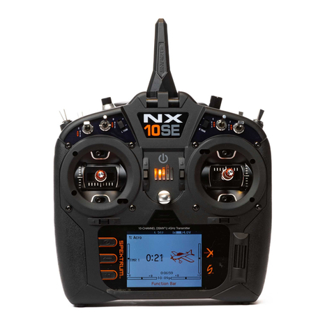
Spektrum
Spektrum NX10SE instruction manual
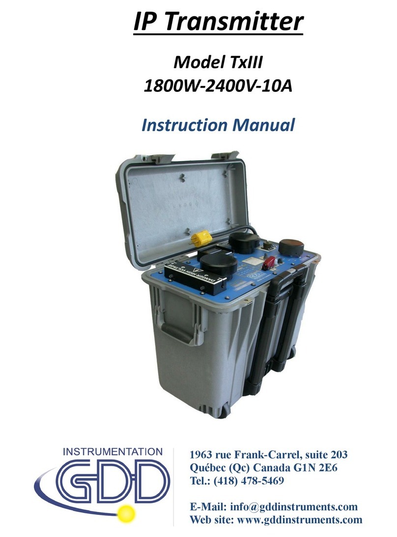
GDD Instrumentation
GDD Instrumentation TxIII instruction manual
Harris Broadcast
Harris Broadcast Flexiva FAX 5KW Technical manual
Hawk
Hawk Intelligent 2000-SAN Series instruction manual
ascon
ascon ATT1 quick start guide
Black Box
Black Box IC565A installation guide

Oehlbach
Oehlbach BTT 5000 user manual
Festo
Festo SDAS-MHS Translation of the original instructions
Produal
Produal Proxima WBU Commissioning and Maintenance Instructions
RKI Instruments
RKI Instruments 65-2397RK Operator's manual
