Gerateanordnung
im
Audio-Rack
Als
Audio-Einbau-
Rack
werden
die
Ausfiihrungen
LA-V4500
oder
LA-4500
empfohlen.
ZUR
BEACHTUNG:
*
GSelbst
bei
Verwendung
eines
nicht
gekennzeichneten
Audio-Racks
unbedingt
geniigend
Raum
zwischen
den
Komponenten
freilassen,
damit
die
Warme
abgeleitet
werden
kann,
und
darauf
achten,
da
Verstarker
und
Tuner
durch
ein
Regal
getrennt
sind.
‘
‘
*
Wenn
kein
Audio-Rack
verwendet
wird,
ist
es
zu
empfehlen,
den
Verstarker
Uber
dem
Tuner
anzuordnen,
damit
die
Warme
wirksam
abgeleitet
werden
kann.
.
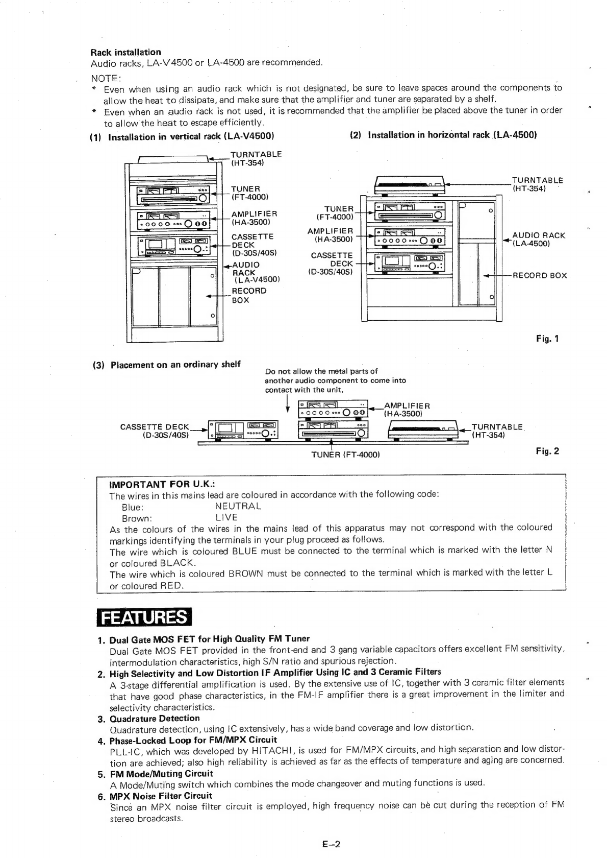
(1)
Einbau
im
Vertikalrack
(LA-V4500)
(2)
Einbau
im
Horizontalrack
(LA-4500)
PLATTEN-
SPIELER
(HT-354)
PLATTEN-
SPIELER
TUNER
(HT-354)
(FT-4000)
:
TUNER
ers
il
Ken
(FT-4000)
(HA-3500)
VERSTAR-
;
KER
AUDIO-RACK
ei
(HA-3500)
(LA-4500)
(D-308/40S)
CASSETTEN-
DECK
AUDIO-RACK
_—_(D-30S/40S)
SCHALLPLAT-
(LA-V4500)
TEN-BOX
SCHALLPLAT-
TEN-BOX
Abb.
1
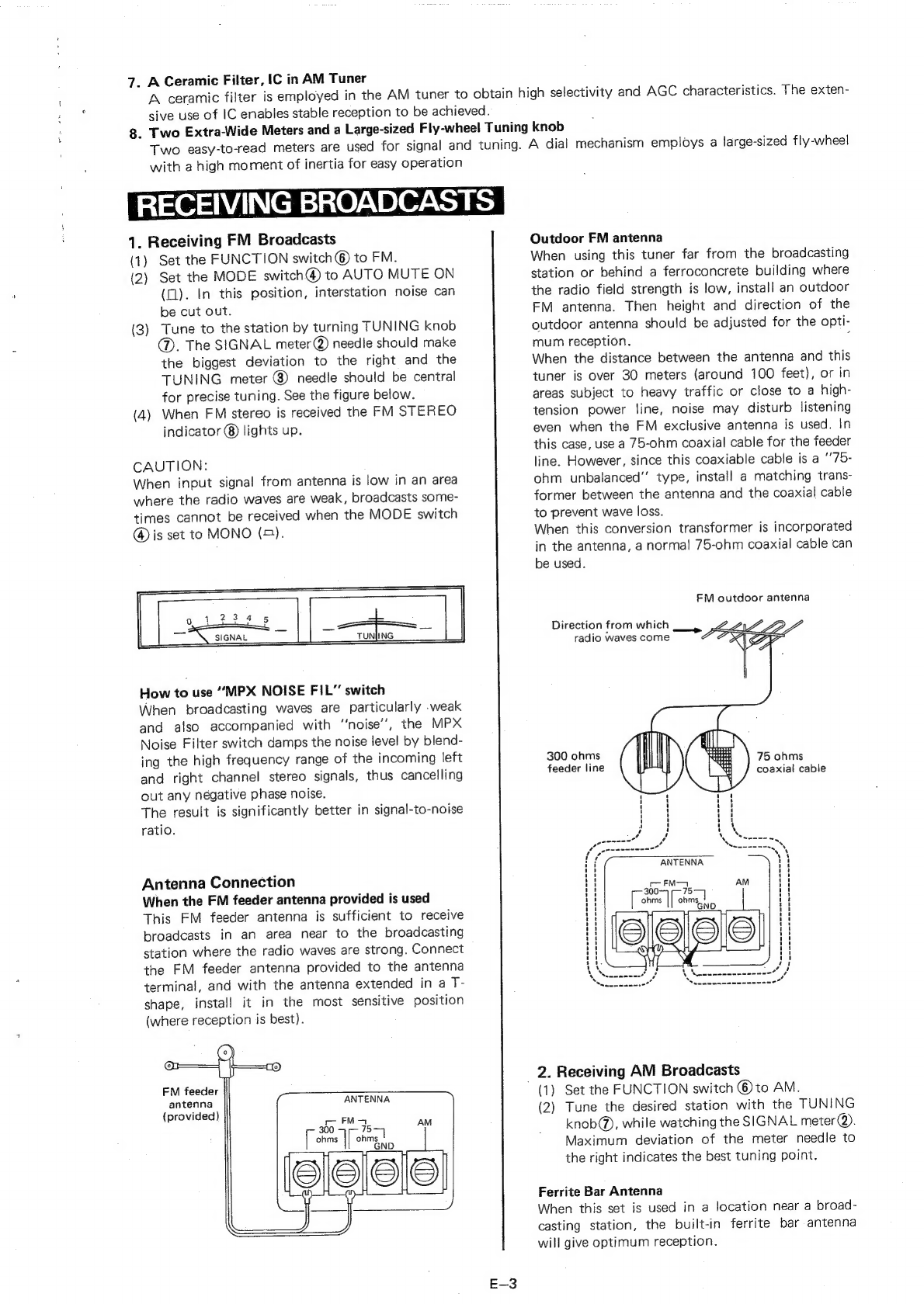
(3)
Aufstellen
auf
einem
gewdhnlichen
Regal
Darauf
achten,
da&
die
Metallteile
eines
anderen
Audiobausteins
nicht
mit
dem
Gerat
in
Beriihrung
kommen.
VERSTARKER
(HA-3500)
PSS
PLATTENSPIELER
(HT-354)
CASSETTENDECK
(D-30S/40S)
TUNER
(FT-4000)
Abb.
2
MERKMALE
1.
Dual-Gate
MOS
FET
Das
Eingangstei!
ist
mit
einem
Dual-Gate
MOS
FET
und
einem
Dreifach-Abstimmkondensator
bestuckt.
Aus-
gezeichnete
UKW-Empfindlichkeit,
Intermodulations-Charakteristik,
hoher
Fremdspannungsabstand
und
Nebenwellensperrung
werden
dadurch
sichergestellt.
2.
Verzerrungsarmer
ZF-Verstarker
mit
hoher
Trennscharfe,
bestiickt
mit
IC
und
drei
Keramikfiltern
Ein
dreistufiger
Differentialverstarker
ist
eingebaut.
Durch
Einsatz
von
integrierten
Schaltkreisen
(ICs)
und
drei
Keramikfiltern
mit
gro&er
Flankensteilheit,
wird
im
UKW-ZF-Verstarker
eine
wesentliche
Verbesserung
der
Grenzwert-
und
Abstimmcharakteristik
erzielt.
3.
Quadraturdemodulator
Kennzeichen
einer
Quadraturdemodulation
unter
Einsatz
von
ICs
sind
groRe
Bandbreite
und
geringe
Verzerrung.
4.
Phasenstarre
Schleifenschaltung
(PLL
IC)
im
UKW-Decoder-Schaltkreis
Die
von
HITACHI
entwickelte
PLL
IC
wird.fiir
die
UKW-MPX-Schaltung
eingesetzt
und
gewahrleistet
optimale
Stereo-Kanaltrennung
sowie
geringe
Verzerrung;
ebenfalls
ist
er
unempfindlich
gegen
Temperaturschwankun-
gen
und
bestandig
gegen
Alterung.
:
5,
UKW-Betrieb/Muting-Schaltung
Ein
Schalter,
der
Betriebsartumschaltung
mit
einer
Stillabstimmung
kombiniert,
ist
eingebaut.
6.
MPX-Rauschfilter-Schaltung
Aufgrund
eines
Multiplex-Rauschfilter-Schaltkreises,
kann
beim
Empfang
von
UKW-Stereosendungen
hoch-
frequentes
Rauschen
ausgeschaltet
werden.
7.
Keramikfilter,
IC
im
MW-Tunerteil
Zum
Erzielen
hoher
Trennscharfe
und
fir
einen
automatischen
Schwundausgleich
wird
ein
Keramikfilter
im
MW-Teil
des
Tuners
eingesetzt.
Der
integrierte
Schaltkreis
(IC)
gewahrleistet
einen
stabilen
Empfang.
8.
Zwei
iibergroRe
Anzeigeninstrumente
und
ein
Sendereinstellknopf
mit
gro&formatigem
Schwungrad
Fiir
genaues
Ablesen
und
optimalen
Empfang
ist
der
Tuner
mit
einem
Feldstarke-Instrument
und
einem
Mitten-
abstimm-Instrument
ausgestattet.
Der
Sendereinstellmechanismus
verwendet
ein
gro&formatiges
Schwungrad
mit
hohem
Tragheitsmoment
fir
leichte
Bedienung.
D-2