manuals.online logo
Brands
  1. Home
  2. •
  3. Brands
  4. •
  5. Hitachi
  6. •
  7. TV
  8. •
  9. Hitachi 55DMX01W User manual

Hitachi 55DMX01W User manual

Other manuals for 55DMX01W

1

Other Hitachi TV manuals

Hitachi 42PD6000TA User manual

Hitachi

Hitachi 42PD6000TA User manual

Hitachi HK5600 User manual

Hitachi

Hitachi HK5600 User manual

Hitachi 27AX4B, 27AX3B, 27AX0B User manual

Hitachi

Hitachi 27AX4B, 27AX3B, 27AX0B User manual

Hitachi LE42S605 User manual

Hitachi

Hitachi LE42S605 User manual

Hitachi 40HBD06U User manual

Hitachi

Hitachi 40HBD06U User manual

Hitachi ULTRAVISION LE22S314 Assembly instructions

Hitachi

Hitachi ULTRAVISION LE22S314 Assembly instructions

Hitachi 24HXT15U User manual

Hitachi

Hitachi 24HXT15U User manual

Hitachi 15LD2200 User manual

Hitachi

Hitachi 15LD2200 User manual

Hitachi 57S715 User manual

Hitachi

Hitachi 57S715 User manual

Hitachi 55R81 User manual

Hitachi

Hitachi 55R81 User manual

Hitachi C2119T User manual

Hitachi

Hitachi C2119T User manual

Hitachi C21-FL21F User manual

Hitachi

Hitachi C21-FL21F User manual

Hitachi C1714TE User manual

Hitachi

Hitachi C1714TE User manual

Hitachi 24HBT45U User manual

Hitachi

Hitachi 24HBT45U User manual

Hitachi LE55S606 User manual

Hitachi

Hitachi LE55S606 User manual

Hitachi 57F59A User manual

Hitachi

Hitachi 57F59A User manual

Hitachi 51F710 User manual

Hitachi

Hitachi 51F710 User manual

Hitachi C2178FS User manual

Hitachi

Hitachi C2178FS User manual

Hitachi P50H401/DW3-U User manual

Hitachi

Hitachi P50H401/DW3-U User manual

Hitachi 50HYT62U User manual

Hitachi

Hitachi 50HYT62U User manual

Hitachi 50PD960DTA Installation instructions

Hitachi

Hitachi 50PD960DTA Installation instructions

Hitachi L26VG07U User manual

Hitachi

Hitachi L26VG07U User manual

Hitachi 43HB6J02U User manual

Hitachi

Hitachi 43HB6J02U User manual

Hitachi C24W430N User manual

Hitachi

Hitachi C24W430N User manual

Popular TV manuals by other brands

Philips 32PFL7403D null

Philips

Philips 32PFL7403D null

Philips 19PFL3403D null

Philips

Philips 19PFL3403D null

Philips 19PFL5403D null

Philips

Philips 19PFL5403D null

Philips 32PFL7605C null

Philips

Philips 32PFL7605C null

Philips 32PFL7603D - annexe 1 null

Philips

Philips 32PFL7603D - annexe 1 null

Haier HS-2190 null

Haier

Haier HS-2190 null

Philips 19PFL3404D null

Philips

Philips 19PFL3404D null

Toshiba 27A10 owner's manual

Toshiba

Toshiba 27A10 owner's manual

Philips 42PF9630A/37 user manual

Philips

Philips 42PF9630A/37 user manual

DAEWOO ELECTRONICS DTQ-14V1FC Service manual

DAEWOO ELECTRONICS

DAEWOO ELECTRONICS DTQ-14V1FC Service manual

Changhong Electric uhd55b6000is Operation manual

Changhong Electric

Changhong Electric uhd55b6000is Operation manual

Philips Matchline 21CE7551 operating instructions

Philips

Philips Matchline 21CE7551 operating instructions

Panasonic Genus TX-G10 operating instructions

Panasonic

Panasonic Genus TX-G10 operating instructions

Toshiba 19A20 Service manual

Toshiba

Toshiba 19A20 Service manual

Philips 25PT4523-16 manual

Philips

Philips 25PT4523-16 manual

Sony XBR-100Z9D reference guide

Sony

Sony XBR-100Z9D reference guide

Philips PR0930X3 owner's manual

Philips

Philips PR0930X3 owner's manual

Philips Brilliance 231P4QPY user manual

Philips

Philips Brilliance 231P4QPY user manual

manuals.online logo
manuals.online logoBrands
  • About & Mission
  • Contact us
  • Privacy Policy
  • Terms and Conditions

Copyright 2025 Manuals.Online. All Rights Reserved.

DLPTMTECHNOLOGY REAR PROJECTION TELEVISION
OPERATING GUIDE
IMPORTANT SAFEGUARDS 2-4
FIRST TIME USE 5-24
THE REMOTE CONTROL 25-37
ULTRATEC BIT MAP
ON SCREEN DISPLAY 38-68
USING THE DLP TMTECHNOLOGY
REAR PROJECTION TV AS A PC
MONITOR
69-79
LAMP REPLACEMENT
PLUG AND PLAY
TRADEMARK ACKNOWLEDGMENT
AGENCY REGULATORY INFORMATION
USEFUL INFORMATION
SPECIFICATIONS
SERVICE HOTLINE
FEATURE INFORMATION
80-91
C Lp. Digital Light Processing, DLP, Digital Micromirror Device and DMD are trademarks of Texas Instruments.
The DLP logo is a trademanrk of Texas Instruments.
A]BU6IIISflIIIIB_E0{X0L06f
IMPORTANT
Follow all warnings and instructions marked on this Rear Projection Television.
,_,_, WARNING
RISK OF ELECTRIC SHOCK
DO NOT OPEN The lightning flash with arrowhead symbol, within an equilateral
_ I _, _ _ :!aa_nnc_e:_ti!1sia;fv!_ittdad_!_`_ic!:snrttti:h:_eee_ursa_r!!_ct_he_ne!:r_eis_tehtehc`!ftuiy_!s!:t!da
CAUTION: TO REDUCE THE RISK OF ELECTRIC SHOCK,
DO NOT REMOVE COVER (OR BACK).
NO USER SERVICEABLE PARTS INSIDE.
REFER SERVICING TO QUALIFIED SERVICE PERSONNEL.
The exclamation point within an equilateral triangle, is intended to
alert the user to the _ of important operating and
maintenance (servicing) instructions in the literature accompanying
the appliance.
WARNING:
TO PREVENT FIRE OR SHOCK HAZARD, DO NOT EXPOSE
THIS REAR PROJECTION TELEVISION TO RAIN OR MOISTURE.
NOTE: ¥There are no user serviceable parts inside the Rear Projection Television.
¥Model and serial numbers are indicated on back side of the Rear Projection
Television.
I CAUTION: TO PREVENT ELECTRIC SHOCK, MATCH WIDE BLADE OF PLUG TO WIDE SLOT, FULLY INSERT I
CAUTION: Adjust only those controls that are covered in the instructions, as improper changes or modifications
not expressly approved by HITACHI could void the user s warranty.
MODIFICATIONS: The FCC requires the user to be notified that any changes or modifications made to this device that
are net expressly approved by Hitachi America, Ltd. Home Electronics Division may void the user s
warranty,
POWER SOURCE
This Rear Projection Television is designed to operate on 120 Volts 60Hz, AC
current. Insert power cord into a 120 Volt 60Hz outlet.
TO PREVENT ELECTRIC SHOCK, DO NOT USE THE REAR PROJECTION
TELEVISION S PLUG WITH AN EXTENSION CORD, RECEPTACLE, OR OTHER OUTLET
UNLESS THE BLADES AND GROUND TERMINAL CAN BE FULLY INSERTED TO
PREVENT BLADE EXPOSURE.
NEVER CONNECT THE DLP TM REAR PROJECTION TELEVISION TO 50HZ, DIRECT
CURRENT, OR ANYTHING OTHER THAN THE SPECIFIED VOLTAGE.
INOTE: This Rear Projection Television receiver will display closed captioning, (_c"_ or [_ ), in accordance
with paragraph 15.119 of the FCC rules.
_. CAUTION: Never remove the back cover of the Rear Projection Television as this can expose you to very high voltages
and other hazards. If the Rear Projection Television does net operate properly, unplug the Rear Projection
Television and call your authorized dealer or service shop.
2
IMPORTANT
IMPORTANT SAFEGUARDS
CAUTION:
¥ Read all of these instructions.
¥ Save these instructions for later use.
¥ Follow all warnings and instructions marked
on the Rear Projection Television receiver.
SAFETY POINTS YOU SHOULD KNOW ABOUT YOUR
HITACHI REAR PROJECTION TELEVISION
RECEIVER
Our reputation has been built on the qua@y, performance, and ease of service of HITACHI Rear Projection Television receivers
Safety is also foremost in our minds Jn the design of these units TO help you operate these products properly, this section illustrates safety tips which will be of benefit to you
Please read Jt carefuJJy and apply the knowledge you obtain from Jt to the proper operation of your HITACHI Rear Projection Television receiver
Please fiJJ out your watYanty card and mail it to HITACH This will enable HTACH to notify you promptly in the improbable event that a safety problem should be discovered in
your product model
FORYOURPERSONALSAFETY
1 This Rear Projection Television set is equipped with
a polarized alternating-current line plug (a plug
having one blade wider than the Other i This plug
will tit into the power outlet only one way This is a
safety feature¸ if you are unable to insert the plug
fully into the power outlet, try reversing the plug if
the p_ug should still fail to fit, contact your electrlcJan
to replace your obsolete outlet Do not defeat the
safety purpose of the polarized plug
2 When the power col_l or plug is damaged or frayed,
unplug the Rear Projection Television set from the
wall outJet and refer sen4cing to qualified service
personnel
3 Do not overload wall outJets and extension cords as
this can result Jnfire or electric shock¸
4 Do not allow anything to rest on or rell over the
power cord, and do not place the Rear Projection
Television where the power cord is subject to traffic
or abuse¸ This may result in a shock or fire hazard¸
5 Do not attempt to service the Rear Projection
Television set yourseJf as opening or removing
covers may expose you to dangerous voltage or
other hazards¸ Refer all servicing to qualified
service personnel¸
6 Never push objects of any kind into the Rear
Projection Television sets cabinet slots as they may
touch dangerous voltage points or short out pads
that could result in a fire or electric shock¸ Never
spill liquid of any kind on the Rear Projection
Television set.
7If the Rear Projection Television set has been
dropped or the cabinet has been damaged, unplug
the Rear Projection Television set from the wall
outlet and refer servicing to qualified service
personnel
8if liquid has been spilled into the Rear Projection
Television set, unplug it from the wall outlet and
refer service to qualified service personnel
9 Do not subject your Rear Projection Television set
to impact of any kind Be careful not to damage the
screen surface
10 Unplug the Rear Projection Television set from the
wall outlet before c_eaning Use a damp cloth for
cleaning Do not use liquid or aerosol cleaners
11-1 Do not place the Rear Projection Television set
on an unstable cart, stand, or table The Rear
Projection Television set may fall, causing
serious injury to a child or an adult, and serious
damage to the appliance Use only with a cart or
stand recommended by the manufacturer, or
sold with the Rear PrejectJon Television set Wall
or shelf mounting should follow the
manufacturers instructions, and should use a
mounting kit approved by the manufactuler
11-2 An appliance and cart combination should be
moved with care Quick stops, excessive force,
and uneven surfaces may cause the appliance
and cart combination to overturn¸
PROTECTION AND LOCATION OF YOUR SET
12 Do not use the Rear Projection Television set near
water, for example, near a bathtub, washbowl,
kitchen sink, or laundry tub, in a wet basement, or
near a swimming pool, etc
¥ Never expose the set to rain or water If the set has
been exposed to rain or water, unplug set from walJ
outlet and refer to qualified sen/ice personnel
13 Choose a place where light (artificial or sunlight)
does not shine directly on the screen
14 Avoid dusty places, since accumulated dust inside
the chassis may cause failure of the set when high
humidity persists
15 The set has s_ots or openings in the cabinet for
ventNation purposes which provide reliable
operation of the receiver and protect the Rear
Projection Television from overheating These
openings must not be blocked or covered
¥ Never cover the slots or openings with cloth or
other material
¥ Never block the bottom ventilation slots of the set
by placing it on a bed, sofa, rug, etc
¥ Never place the set near or over a radiator or heat
generator¸
¥ Never place the set in a built-in enclosure, unless
proper ventilation is provided
3
/k SAFETY TIPS
PROTECTION AND LOCATION OF YOUR REAR PROJECTION TELEVISION
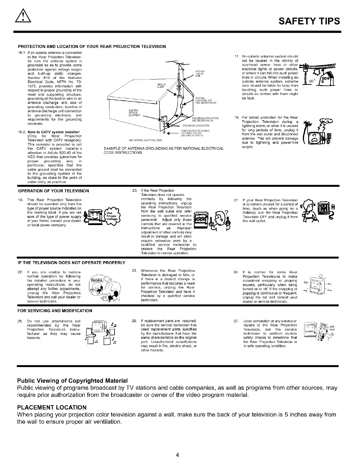
16-1 if an outside antenna isconnected
to the Rear Projection Television,
be sure the antenna system is
grounded so as to provide some
protection against voltage surges
and built-up static charges¸
Section 810 of the National
Electrical Code, NFPA No 70_
1975, provides information with
respect to proper grounding of the
mast and supporting structure,
grounding of the lead4n wire to an
antenna discharge unit, size of
grounding conductors, location of
antenna discharge unit connection
to grounding electrode, and
requirements for the grounding
electrode¸
16-2. Note to CATV system installer:
{Only for Rear Projection
Television with CATV reception)
This reminder is provided to call
the CATV system installer s
attention to Article 820_40 of the
NEe that provides guidelines for
proper grounding and, in
particular, specifies that the
cable ground shall be connected
to the grounding system of the
building, as close to the point of
cable entry as practical
EXAMPLE OFANTENNA GROUNDING AS PER NATIONALELECTRICAL
CODEiNSTRUCTIONS
17 An outside antenna system should
not be located in the vicinity of
overhead power lines or other_
e]ectrica[ lights or power circuits,
or where it call fall into such power
lines or circuits When installing an
outside antenna system, extreme
care should be taken to keep from
touching such power lines or
circuits as contact with them might
be fatal
18 For added protection for the Rear
Projection Television during a
lightning storm, or when it is unused
for long periods of time, unplug it
flora the wall outlet and disconnect
antenna This will prevent damage
due to lightning and powerdine
surges
OPERATION OF YOUR TELEVISION
19 This Rear Projection Television
should be operated only from the
type of power source indicated on . ._
the marking label If you are not
sure of the type of power supply
at your home, consult your dealer
or local power company
20 If the Rear Projection
Television does not operate
normally by following the
operating instructions, unplug
the Rear Projection Television
fzom the wall outlet and refer _ _,,,_?
personnel Adjust only thOSe
controls that are covered in the
instructions as improper _
adjustment of other cont_ls may
result in damage and will often
require extensive work by a
qualified service technician to
restore the Rear Projection
Television to normal operation¸
21 If your Rear Projection Television r._*-_ ._.
is to remain unused for a period of
time, (such as when going on a
holiday), turn the Rear Projection
Television OFF and unplug it flora
the wall outJet.
IF THE TELEVISION DOES NOT OPERATE PROPERLY
22 If you are unable to restore
normal operation by following
the detailed procedure in your
operating instructions, do not
attempt any further adjustments
Unplug the Rear Projection
Television and carl your dealer or
service technician
23 Whenever the Rear Proiection
Television is damaged or falls, or
if there is a distinct change in
performance that indicates a need
for service, unplug the Rear
Projection Television and have it
checked by a qualified service
technician
24 It is normal for some Rear
Televisions to make _'_ ,,Projection
occasional snapping or popping _
sounds, particularly when being
turned on ot off If the snapping or _,._
popping is continuous ot frequent,
unplug the set and consult your
dealer or service technician
FOR SERVICING AND MODIFICATION
25 Do not use attachments not
recommended by the Rear
Projection Television manu-
facturer as they may cause
hazards
26 If replacement parts are required,
be sure the service technician has
used replacement parts specified
by the manufacturer that have the
same characteristics as the original
part¸ Unauthorized substitutions
may result in fire, electric shock, or
other hazards¸
27 Upon completion of any service or
repairs to the Rear Projection
Television, ask the service
technician to perform routine
safety checks to determine that
the Rear Projection Television is
in safe operating condition
Public Viewing of Copyrighted Material
Public viewing of programs broadcast by TV stations and cable companies, as well as programs from other sources, may
require prior authorization from the broadcaster or owner of the video program material.
PLACEMENT LOCATION
When placing your projection color television against a wall, make sure the back of your television is 5 inches away from
the wall to ensure proper air ventilation.
4
ACCESSORIES
Check to make sure you have the following accessories before disposing of the packing material.
PARTS NAME PART NO. ILLUSTRATION
)RY BATTERY (R6P-AA) FQ00021
"AA" SIZE BATTERY
CLU-579TSI
REMOTE CONTROL
SP-55D
55V TELEVISION STAND
(Not included,order separately)
OPTIONAL
HL01329
H530051
®®®@
@@@
@@@
@%@@
....0 @ 0 ......
©@ee
CUSTOM HITACHI
TELEVISION STAND
Excellent for VCR and video-
tape storage. Special features
include thick top shelf (1 inch),
aluminum column (shark grey
color), glass shelf (green edge)
and black rubber foot.
r i
II II II II II
II II II II II
L_J L_J L_ L_ L_
Z_k CAUTION: Television stand model SP-55D is designed for use with 55DMX01W only. Use of a smaller stand, a non Hitachi
recommended stand or ageneric stand may result in instability, causing possible injury.
REMOTE CONTROL BATTERY INSTALLATION AND REPLACEMENT
1. Open the battery cover of the remote control by pushing the notched BOTTOMVIEW
part of the cover with your fingers and pulling the cover off.
2. Insert two new AA size batteries for the remote control. When l__eo _] i_I
replacing old batteries, push them towards the springs and lift them out.
3. Match the batteries to the (+) and (-) marks in the battery compartment.
4. Replace the cover.
Lift up on tab to
remove back cover.
5
]]
HOW TO SET UP YOUR NEW
HITACHI DLP TMREAR PROJECTION TV
ANTENNA
Unless your Rear Projection TV is connected to a cable TV system or to a centralized antenna system, a good outdoor color TV
antenna is recommended for best performance, However, if you are located in an exceptionally good signal area that is free from
interference and multiple image ghosts, an indoor antenna may be sufficient.
LOCATION
Select an area where sunlight or bright indoor illumination will not fall directly on the picture screen. Also, be sure that the location
selected allows a free flow of air to and from the perforated back cover of the set.
To avoid cabinet warping, cabinet color changes, and increased chance of set failure, do not place the Rear Projection TV where
temperatures can become excessively hot, for example, in direct sunlight or near a heating appliance, etc.
VIEWING
The major benefit of the HITACHI Rear Projection Television is its large viewing screen. To see this large screen at its best, test
various locations in the room to find the optimum spot for viewing.
The best picture is seen by sitting directly in front of the Rear Projection TV and about 10 to 18 feet from the screen. Picture
brightness decreases as the viewer moves to the left and right of the receiver.
During daylight hours, reflections from outside light may appear on the screen, If so, drapes or screens can be used to reduce the
reflection or the Rear Projection TV can be located in a different section of the room.
If the Rear Projection TV s audio output will be connected to a Hi-Fi system s external speakers, the best audio performance will
be obtained by placing the speakers equidistant from each side of the receiver cabinet and as close as possible to the height of
the picture screen center, For best stereo separation, place the external speakers at least four feet from the side of the Rear
Projection TV, place the surround speakers to the side or behind the viewing area. Differences in room sizes and acoustical
environments will require some experimentation with speaker placement for best performance.
Notes
This set has a 200W lamp The lamp rarely breaks If it does, it will make a pop noise
No Items
1 Lamp Explosion
2 On time It takes time (17 seconds) to display picture on television compared to a conventional color tele
vision LED at the front panel indicates the set is under power on condition (See note on page 9)
3 Restart time It takes about 60 seconds for the picture to re-appear, after quickly pressing power OFF
then ON again Three LEDs indicate the set is under power on condition On: Three LED s
blink alternately Off: One LED blinks
4 When power off Fans will keep working for abe/it 2 minutes after power OFF to cool down the lamp
5 Lamp replacement It is recommended that you replace the lamp every 4000 he/its to obtain good picture bright-
ness (This is not a g/larantee that life time of a lamp is 4000 hours)
6 Bright and This set has fixed pixel elements There may be some dark/bdght spots on the
dark spot element However, this is not a defect
7 Sbeaks in Please set proper signal strength You may see streaks in picture on some channels without
Picture proper antenna Streaks may disappear when signal is strong Place antenna and cable
away from the AC power cord
8 Bend, tilt Due to varying signal content, you may see ver[ical or honzontal lines bend occasionally En
PC mode However, this phenomenon is not a defect It s ca/ised by a lack of picture content
due to under-scanning in PC mode
9 PC mode This set provides the best picture quality in SVGA mode It is recommended that you set yo/ir
PC to SVGA mode In OVERSCAN mode, top/bottom icon will be approximately 19% to 50%
within the viewable area, and should be accessible to grab and click Picture is overscanned
when receiving XGA or higher resolution signals
10 Burning Please do not leave the TV set with still pictures like games, stock market qutoes, and other
non moving pictures Otherwise it may cause a pattern burn on the screen
11 Protect Operation When the lamp is cooling down, the remote control does not respond within 15 seconds LED at
when power on the front panel shows if your set accepts remote commands When blinking is slow, your set is
ready to accept remote commands
12 Please do not There is a color wheel spinning at high revolution in the television set g may be broken g yo/i
move your set move yo/ir set before setting power off
when it is on
13 Input/PinP The television CPU sets picture blanking to hide unnecessary noise, until it becomes stable
mode change
14 OSD position/size OSD position/size change according to the picture aspect format, when watching a component
(Y PBPR) signal SDTV (480P): OSD aspect changes when screen format is changed HDTV
(720P): OSD expands horizontally (Both edges of OSD may be hidden accoEding to
circumstances)
6
HOOK-UP CABLES AND CONNECTORS
Most videolaudio connections between components can be made with shielded video and audio cables that have phono
connectors. For best performance, video cables should use 75-Ohm coaxial shielded wire. Cables can be purchased from most
stores that sell audio/video products. Below are illustrations and names of common connectors, Before purchasing any cables,
be sure of the output and input connector types required by the various components and the length of each cable.
300-Ohm Twin Lead Connector
This outdoor antenna cable must be connected to an antenna
adapter (300_Ohm to 75-Ohm).
"F" Type 75-Ohm Coaxial Antenna Connector
For connecting RF signals (antenna or cable TV) to the
antenna terminal on the Rear Projection Television.
Phono Connector
Used on all standard video and audio cables which connect to
inputs and outputs located on the Rear Projection Television s
rear jack panel and front control panel.
D-SUB MINI 15-Pin Cable (Optional)
This cable is used to connect a computer VGA output to the D-
SUB input.
Optical Cable
This cable can be used to connect to a component with an
Optical Audio Out jack, such as a Dolby* Digital DVD player or
an HDTV Set Top Box. Use this cable for the best sound quality.
S-VIDEO (Super Video) Connector (Optional)
This connector is used on camcorders, VCRs, and laserdisc
players with an S-VIDEO feature in place of the standard video
cable to produce ahigh quality picture.
2
3.5 mm RCA Type
Stereo _lugs
Mini pBug
Stereo Cable (3.5 mm plug to 3.5 mm plug) (Optional)
This cable is used to connect from AUDIO OUT jack on the
back of the computers sound card to the PC AUDIO INPUT
jack of the Rear Projection Television.
ANTENNA CONNECTIONS TO REAR JACK PANEL
VHF (75-Ohm) antenna/CATV (Cable TV)
When using a 75-Ohm coaxial cable system, connect the outdoor
antenna or CATV coaxial cable to the ANT A (75-Ohm) terminal. If
you have a second antenna or cable TV system, connect the coaxial
cable to the ANT B terminal.
VHF (300-Ohm) antenna/UHF antenna
When using a 300-Ohm twin lead from an outdoor antenna, connect
the VHF or UHF antenna leads to screws of the VHF or UHF
adapter. Plug the adapter into the antenna terminal on the TV.
When both VHF and UHF antennas are connected
Attach an optional antenna cable mixer to the TV antenna
terminal, and connect the cables to the antenna mixer. Consult
your dealer or service store for the antenna mixer.
To outdoor antenna
or CATV cable
TO CONVERTER
11_ ANTB
TO secon6 antenna
or cable system
To outdoor VHF
or UHF anter_na
To outdoor
To UHF ANT A/ANT B antenna or
Antenna II CATV system
1"
Antenna mi×et
7
_FRONT PANEL CONTROLS
FRONT VIEW
4_
Push to open door for
front controls and inputs.
DIGITAL
PUSH
Shownwith Control
PanelDoorClosed
LAM' ![_p f_OWE _ _ D I G I T A L
A _, ,Nf V,2
pC ALjD_O J
l: ................VV
t l ....f Tr TTT [Shown with Control
Panel Door Open
(_) REMOTE CONTROL Sensor
Point your remote at the screen when selecting channels, adjusting volume, etc. The remote control sensor is inside the screen.
PERFECT PICTURE Sensor
The PERFECT PICTURE sensor will make automatic picture adjustments depending on the amount of light in the room to give the
best picture. (see page 59)
LAMP Indicator - NORMAL OPERATION INDICATOR IS OFF
If light is lit, the lamp has failed. See page 80-83 for lamp replacement procedure. Consult your Hitachi dealer for proper part. If
light is blinking, lamp cover is not assembled securely after replacement.
(_ TEMP Indicator
This light is off during normal operation.
Ifthis indicator is lit, the optic unit is too hot. If this indicator is blinking, the cooling fan has stopped. Please call service.
8
FRONT PANEL CONTROLS
(_ POWER Light
This light is on during normal operation,
Light Blinking Slowly (2 seconds): Rear Projection Television lamp is cooling down. It takes 12-15 seconds to warm up and
about 2 minutes to cool down.
POWER Button
Press this button to turn the TV on or off.
(_) FRONT INPUT JACKS (for VIDEO: 3 and PC2 AUDIO)
Use these audio/video jacks for a quick hook-up from a camcorder or VCR to instantly view your favorite show or new recording,
Press the INPUT button until VIDEO: 3 appears in the top right corner of the TV screen, If you have mono sound, insert the audio
cable into the left audio jack, VIDEO: 3 audio input jacks can be used for PC2 audio when a PC is connected to front input VIDEO:
3jack, When using S-Video cable on the front panel, make sure the arrow ( 1') marking on the S-Video cable points to the left, to
properly insert the S-Video cable into your television.
(_PC INPUT 2 (Front)
Use this 15 pin D-Sub input for a quick hook up from your PC connection.
(_) FV/PC Button
Press this button to switch from TV, PC INPUT 1 (PC1) and PC INPUT 2 (PC2). Your selection is shown in the top right corner of
the screen.
(_) INPUT/EXIT Button
Press this button to select the current antenna source, VIDEO: 1, 2, 3 or alternate antenna source. Your selection is shown in the
top right corner of the screen. This button also serves as the EXIT button when in MENU mode.
INOTE: COMPONENT INPUT takes priority over S-VIDEO input, and S-VIDEO input takes priority over VIDEO input.
MENU Button
This button allows you to enter the MENU, making it possible to set TV features to your preference without using the remote.
This button also serves as the SELECT button when in menu mode.
VOLUME Level
Press these buttons for your desired sound level, The volume level will be displayed on the TV screen. These buttons also serve
as the cursor left (_1) and right (1_) buttons when in MENU mode.
CHANNEL Selector
Press these buttons until the desired channel appears in the top right corner of the TV screen. These buttons also serve as the
cursor down (_') and up (&) buttons when in MENU mode.
NOTES:
1, INDICATOR ACTION
LAMP LED
TEMP
LED
POWER
INDICATION
LIGHT ON
BLINKING
LIGHT ON
BLINKING
LIGHT ON
SLOWLY BLINKING
MEANING
NO LAMP LIGHT
or BROKEN LAMP
WRONG LAMP UNIT
ASSEMBLY
Too Hot inside the
OPTIC unit
COOLING FAN STOPPED
NORMAL
OPERATION
COOL DOWN
Need to exchange if
LAMP still does not light by
Power On again.
Check assembly condition of
LAMP UNiT
Call Service
2. If the LAMP, TEMP, and POWER LED are blinking in the order below, the Rear Projection Television is warming up.
LAMP --_TEM P --_ POWER
I9
FRONT PANEL JACKS AND CONNECTIONS
The front panel jacks are provided as a convenience to allow you to easily connect a VCR, PC or camcorder as shown in the
following examples:
.......
Back of VCR
D-SUB 15 Pin
Audio Cable 41- RGB Cable
(Optiona (Optional)
__ PC
Back of PC
S VHS Video Camera Output
NOTE:
NOTE:
Completely insert connection cord plugs when connecting to front panel jacks. If you do not, the played back picture may
be abnormal. If you have an S-VHS VCR, use the SqNPUT cable in place of the standard video cable. If you have a
mono VCR, insert the audio cable into the left audio jack of your TV. INPUT 3 audio can be used for PC INPUT 2 audio
when a PC INPUT 2 is connected.
Optional adapter for *Apple @ Macintosh @ computers. If the optional AESP model G301/U Macintosh to VGA@ adapter
connector is configured and connected between Macintosh video out and the Rear Projection Television video in, the
Macintosh is forced to boot in 640 x 480/60 Hz or 800 x 600/60 Hz mode (set mode) because the operational adapter
correctly manipulates the Macintosh sense pins.
For the optional adapter to work, it s DIP switch settings should be # 2, 3, 6, 7 = ON and # 1, 4, 5, 8, 9, 10 = OFF.
See below: Example - See Switch Instructions for details.
Mode 5 = 2367 (SVGA 800 x 600/60 Hz configuration)
(VGA 640 x480/60 Hz configuration)
Composite Separate Sync
n[ ],
ON
23 67
1 45 8910
OFF
UI I U U
10