system.
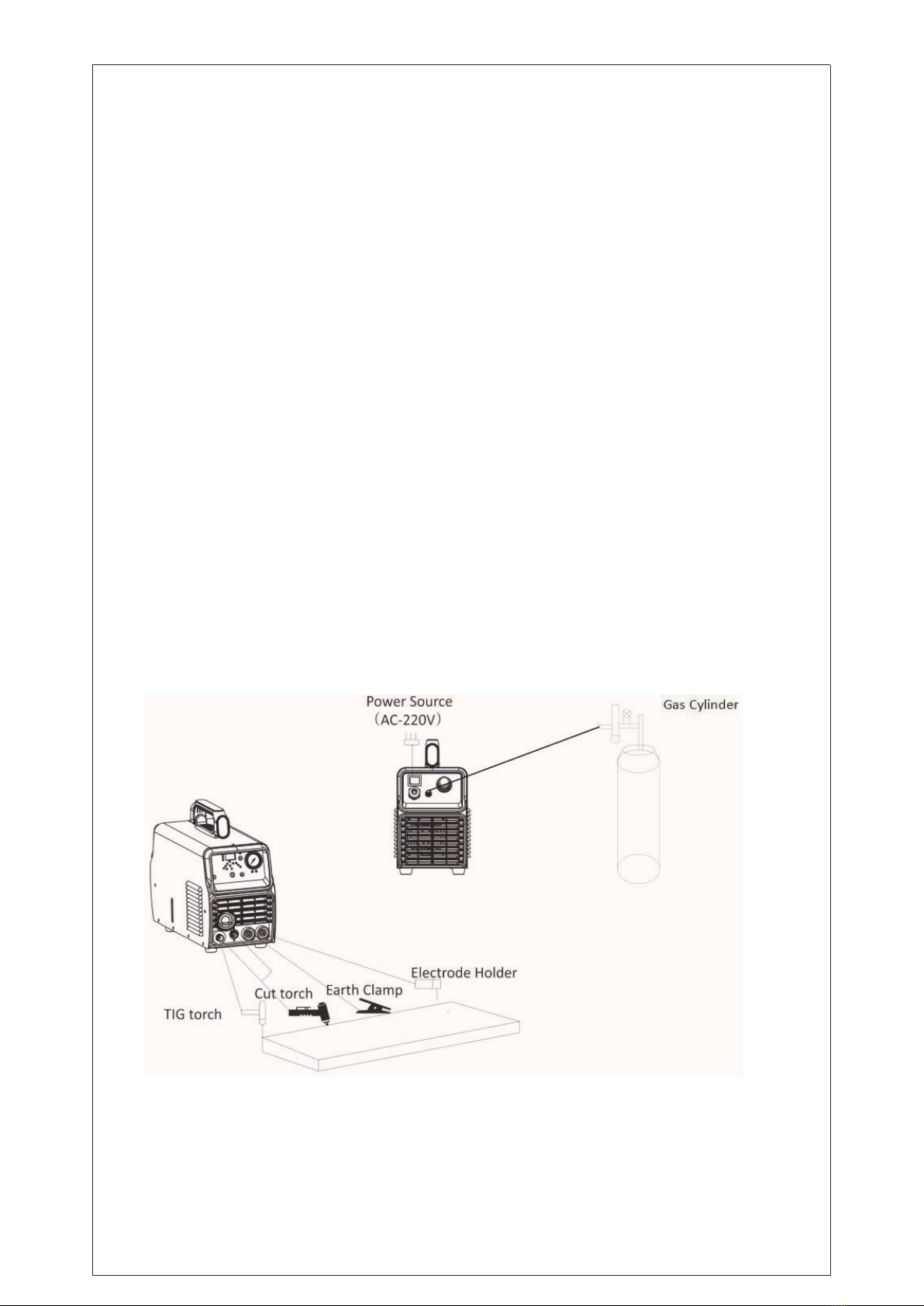
6.2 Connect the protective gas source. The gas supply passage shall include a gas cylinder, an
argon gas pressure reducing flowmeter and a gas pipe. The connecting portion of the gas pipe
shall be fastened with a hose clamp or other articles to prevent argon gas leakage and air ingress.
6.3 Ground the cables with section area no less than 6mm2to the housing, the way is connecting
screw in the back of the power source to ground device, or make sure ground terminal of power
socket is firmly connected. Both ways can be used for absolute safety.
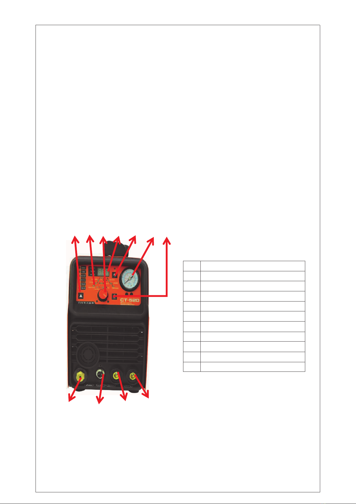
6.4 Plug the quick plug of the loop cable into the quick socket of the welder panel with a polarity
of "+" and follow The hour hand is tightened tightly, and the ground wire clamp at the other end
clamps the workpiece
6.5 When using the foot switch control, connect the two-core aviation and three-core aviation
plugs of the foot switch to the three-core air socket of the local panel.
6.6 According to the input voltage level of the welding machine, connect the power line to the
distribution box of the corresponding voltage level. Do not connect the wrong voltage. Also
ensure that the error of the power supply voltage is within the allowable range.
6.7 When using manual arc welding, install the electrode holder as shown. After the above work
is completed, the welder is finished. In the installation work, welding is available.
7.OPERATION INTRODUCTION
7.1 Use AC TIG welding function description:
7.1.1 Turn on the power switch and the fan inside the machine starts to rotate.
7.1.2 Press the function button and select the desired function to operate.
7.1.3 Turn on the argon switch and adjust the gas flow to the rated standard (see flow meter).
7.1.4 Adjust the ratio of positive and negative current time according to the degree of oxidation
of the surface of the workpiece to be welded.
7.1.5 Press the switch on the torch and the solenoid valve starts. You will hear the high-frequency
spark discharge in the welder. At the same time, there is argon gas flowing out of the torch nozzle.
Note: When welding for the first time, you need to press and hold the switch for a few seconds
before soldering until all the air in the air path is drained. After you stop welding, there will still
be argon flow out in a few seconds. This is specially designed to ensure that the solder joints are
protected before cooling. Therefore, after use, the welding position must be kept for a while after
the arc is extinguished. Open the welding torch.
7.1.6 Adjust the “pre flow”,“post flow”and “down slop”times according to actual needs.
7.1.7 Keep the tungsten electrode and the welding workpiece at a distance of 2-4mm. Press the
torch control switch to generate high-frequency discharge between the torch electrode and the
workpiece. After the ignition starts, the high-frequency arc spark in the welder It disappears
immediately and you can start working.
7.2 Use DC TIG welding function description:
7.2.1 Turn on the power switch and the fan inside the machine starts to rotate.
7.2.2 Press the function key to select the TIG function.
7.2.3 Turn on the argon switch and adjust the gas flow to the rated standard (see flow meter).
4. 5, 6, 7, and 8 in the same description.
7.3 Use DC MMA welding function description:
7.3.1 Turn on the power switch and the fan inside the machine starts to rotate.
7.3.2 Place the "TIG/MMA" switch in the "MMA" position. Determine the appropriate welding
current based on the thickness, station and process conditions of the welded workpiece.
7.3.3 The welding eledctrode clamped by electrode holder can be welded.