Hitbox ARC160D Technical manual


2/18
Z2A5 SC-A0
DIRECTORY
1. SAFETY-------------------------------------------------------------------------------------------------------------------3
2. SYMBOL EXPLANATION--------------------------------------------------------------------------------------------4
3. PRODUCT OVERVIEW-----------------------------------------------------------------------------------------------5
4. FUNCTION OVERVIEW---------------------------------------------------------------------------------------------- 5
5. PERFORMANCECHARACTERISTICS------------------------------------------------------------------------- 5
6. ORDER INFORMATION----------------------------------------------------------------------------------------------6
7. TECHNICAL PARAMETERS----------------------------------------------------------------------------------------7
8. ELECTRICAL SCHEMATIC DIAGRAM--------------------------------------------------------------------------8
9. OPERATION CONTROL AND DESCRIPTION-----------------------------------------------------------------8
10.SYSTEM CHARACTERISTICS-------------------------------------------------------------------------------------9
11. INSTALLATION, DEBUGGING AND OPERATION---------------------------------------------------------10
11.1 Connection of switching box--------------------------------------------------------------------------------10
11.2 Installation----------------------------------------------------------------------------------------------------------10
11.3 Operation-----------------------------------------------------------------------------------------------------------11
11.4 Welding parameters table (for reference only)---------------------------------------------------------11
12. CAUTION--------------------------------------------------------------------------------------------------------------12
12.1 Working Environment------------------------------------------------------------------------------------------12
12.2 Safety Tips----------------------------------------------------------------------------------------------------------12
13. BASIC KNOWLEDGE OF WELDING--------------------------------------------------------------------------12
13.1 Welding Process of MMA--------------------------------------------------------------------------------------13
13.2 Tools for MMA-----------------------------------------------------------------------------------------------------13
13.3 Basic Operation of MMA---------------------------------------------------------------------------------------14
14. MAINTENANCE------------------------------------------------------------------------------------------------------16
15. TROUBLESHOOTING---------------------------------------------------------------------------------------------17
15.1 Common Malfunction Analysis and Solution:----------------------------------------------------------16
APPENDIX A: PACKING, TRANSPORTATION AND STORAGE-------------------------------------------18
A1. Packing---------------------------------------------------------------------------------------------------------------18
A2. Transportation------------------------------------------------------------------------------------------------------18
A3. Storage---------------------------------------------------------------------------------------------------------------18
APPENDIX B: REVISION HISTORY---------------------------------------------------------------------------------18

3/18
1. SAFETY
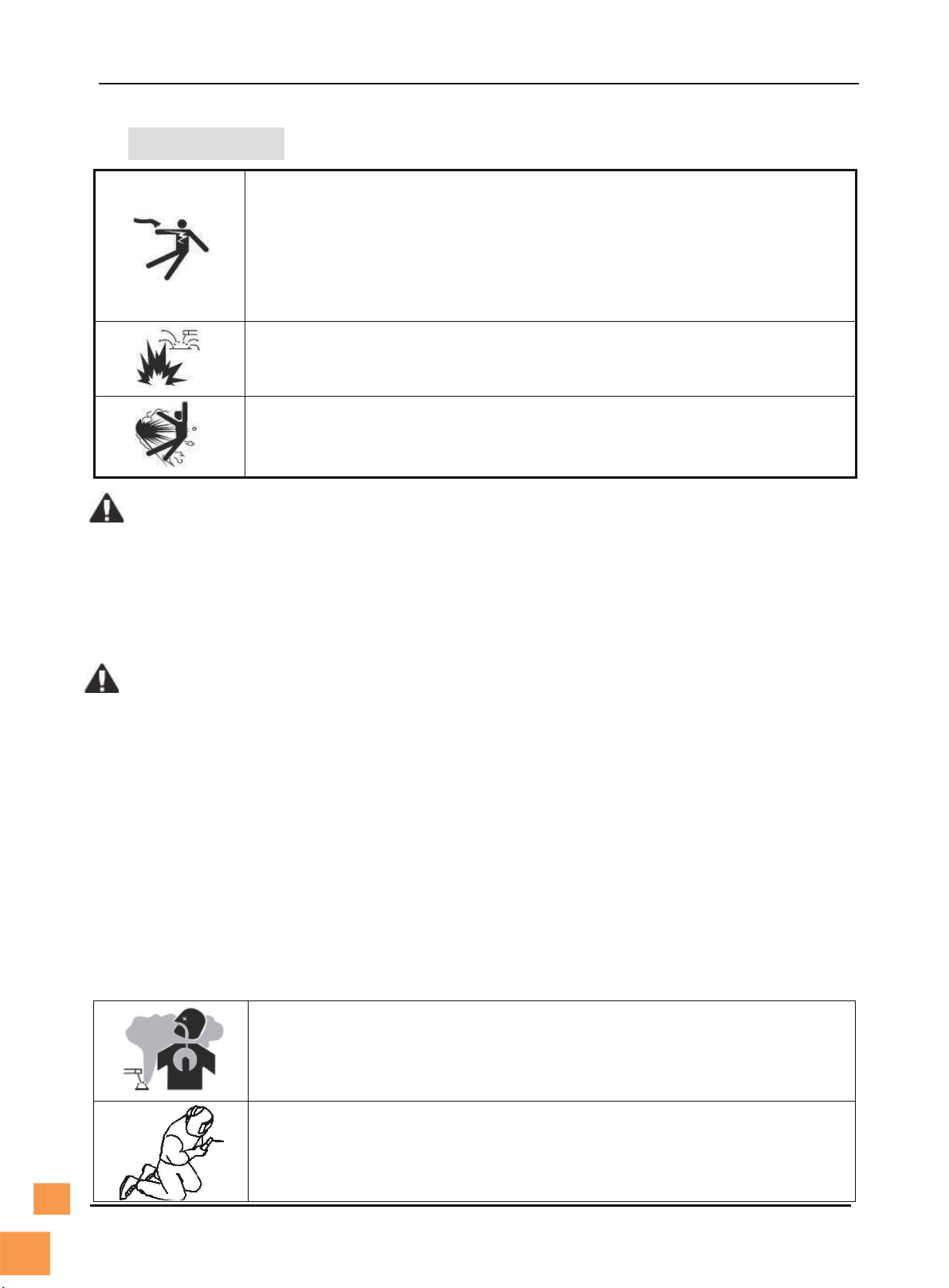
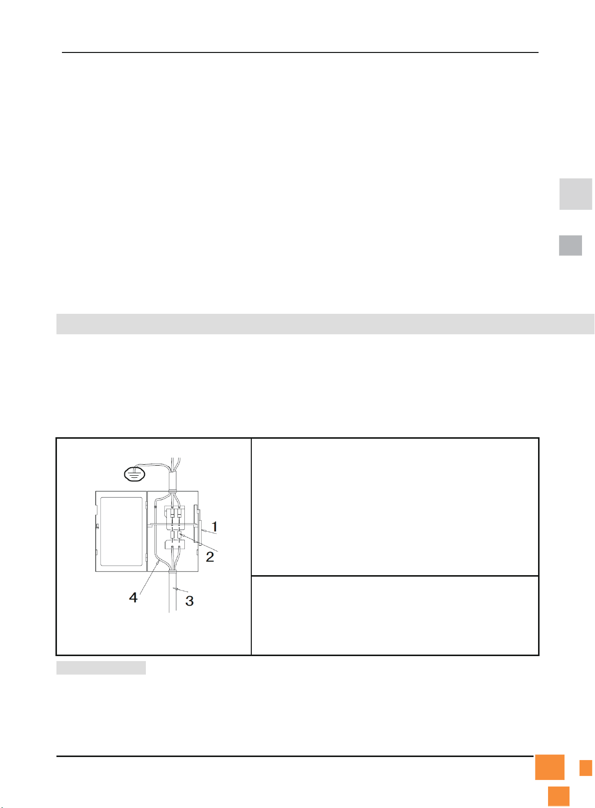
Beware of electric shock!
Install grounding device according to application standard.
Do not touch live parts with naked skin, wet gloves or wet clothes.
Be sure you are insulated from ground and workpiece.
Cover the cover plate of the machine before power on to avoid an electric shock.
Confirm the safety of your working position.
Beware of fire hazard!
Please install the machine on non-combustible materials to avoid a fire.
Make ensure there are no inflammables near the welding position to avoid a fire.
Beware of explosion!
Do not install the machine in an environment with explosive gas to avoid an explosion.
Replacing the components can be dangerous.
Only professionals can replace the components of the machine.
Make sure there are no foreign bodies such as wire leads, screws, gaskets and metal bars falling into the machine
inside when replacing the components.
Make sure the connecting wires inside the machine are correctly connected after replacing the PCBs, and then the
machine can be run. Otherwise, there is a risk of damage to property.
Carrying or moving the machine can be dangerous.
Cut the inputpower off via the switching box before moving the welding machine.
The handle can only be used for moving the welding machine by hand in short distance, and it cannot be used for
lifting. Otherwise, personal injury or property damage may be caused by a drop.
Make sure that the flying rings are tightened, and that the machine enclosure and cover are fixed when moving the
welding machine with a crane,
Two lifting belts should be used when lifting the welding machine, and the angle formed by the lifting belt and the
vertical should be smaller than 15°.
Do not apply any stress on the operation panel and cover when moving the welding machine. Otherwise, personal
injury or property damage may be caused by a drop.
Do not install and run the welding machine when the machine is damaged or lacks any components. Otherwise, fire
hazard or personal injury may be caused.
Precautions for operation
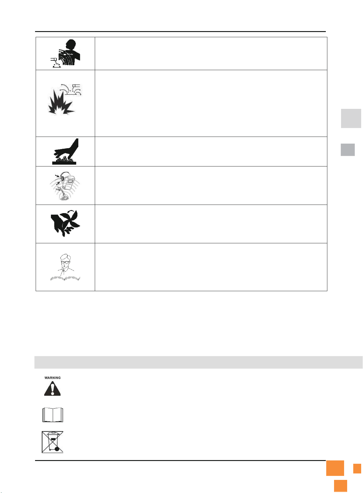
Smoke-may be harmful to your health!
Keep your head away from the smoke to avoid inhalation of waste gas in welding.
Keep the working environment well ventilated with exhaust or ventilation equipment
when welding.
Arc radiation-may hurt youreyes and burn yourskin!
Use proper mask and wear protective clothing to protect your eyes and body.
Use proper mask or curtain to protect onlooker from being injured.

4/18
Magnetic field can makecardiac pacemaker a bit wonky.
People with cardiac pacemaker should consult the doctor before carrying out welding.
Stay away from the power source to reduce the affect of magnetic filed.
Improper use and operation may result in a fire or an explosion.
Welding spark may result in a fire, so please make ensure there are no inflammables
near the welding position, and pay attention to fire safety.
Ensure there is fire extinguisher nearby, and make sure someone has been trained to
operate the fire extinguisher.
Do not cut closed container.
Do not use this machine for pipe thawing.
Hot workpiececancause severe scald.
Do not touch hot workpiece with bare hands.
Cool the welding torch for a while after continuously working.
Excessive noise does great harm to people’s hearing.
Wear ear covers or other hearing protectors when welding.
Give warning to onlooker that noise may be potentially hazardous to hearing.
Moving parts may injure yourbody.
Please keep away from moving parts (like fan).
Each door, panel, cover, baffle plate, and protective device the like should be closed and
located correctly.
Seek professional support when trouble strikes.
When trouble strikes in installation and operation, please inspect according to related
contents in this manual.
If you still cannotunderstand fully, or you still cannot solve the problem, please contact
the dealer or the service center of JASIC to obtain professional support.
Precautions for discard
Pay attention to the following when discarding the welding machine:
Burning the electrolytic capacitors in the main circuit or on the PCBs may cause an explosion.
Burning the plastic parts such as the front panel may produce poisonous gas.
Dispose it as industrial waste.
2. SYMBOL EXPLANATION
Matters to be noticed in operation
Objects to be speciallydescribedandpointed out
It is prohibited to dispose the electrical waste together with othercommon wastes. Please
protect the environment.

5/18
3. PRODUCT OVERVIEW
Unique electric structure and air channel design in this
series of machines can speed up the heat rejection of the
power device as well as improving the duty cycles of the
machines. The unique heat rejection efficiency of the air
channel can effectively prevent the power devices and
control circuits from being damaged by the dust absorbed
by the fan, and the reliability of the machine is greatly
improved thereby.
The machine adopts streamline shape. Frontand rear
panels andhandle are sprayed with rubber oil which gives
good touch feeling.
Fig 1
4. FUNCTION OVERVIEW
Various function designs
Hot start arc ignition function: make the arc ignition in MMA welding easier and more reliable.
Self-adaptive arc force technology: obviously improve the performance of the machine in
long-cable welding and contribute to long-distance welding.
5. PERFORMANCE CHARACTERISTICS
Advanced IGBT inverter technology
Inverting frequency of 42-52 kHz greatly reduces the volume and weight of the welder.
Great reduction in magnetic and resistance loss obviously enhances the welding efficiency
andenergy saving effect.
Working frequency is beyond audiorange, which almost eliminates noise pollution.
Leading control mode
Advanced control technology meets various welding applicationsand greatly improves the
welding performance.
It can be widely used in acid and basic electrode welding.
Easy arc starting, less spatter, stable currentand good shaping.
Nice shape and structure design
Frontand rear panels in shape of streamline make the whole shape nicer.
Excellent insulating property.
Waterproof, antistatic andanticorrosion.

6/18
6. ORDER INFORMATION
ModelFunction Configuration Product Code
ARC160D
Hot start arc ignition
self-adaptive arc force
Anti-stick
MMA/Lift-TIG
VRD
Z2A4
ARC200D Z2A5
7. TECHNICAL PARAMETERS
Technical
Parameter Unit
Model
ARC160D ARC200D
Rated input
voltage
V
AC120V±15%
50/60HZ
AC240V±15%
50/60HZ
AC120V±15%
50/60HZ
AC240V±15%
50/60HZ
Rated input power KVA 5 7.1 6 9.4
Welding current
range
A20-120 20-160 20-140 20-200
V20.8-24.8 20.8-26.4 20.8-25.6 20.8-28
Rated duty cycle①%20 20
No-load voltage V 85 85
Overall efficiency % 85 85
Housing
protection grade
IP 21S 21S
Power factor cosφ0.7 0.7
Insulation grade H H
Standard IEC60974-1
Noise db <70
Size
with
handle②mm 305* 112* 190 mm 335*112*190 mm
Weight kg 3.560 4.220
Applicable
electrode
mm 1.0-3.2 1.0-5.0
“①”- under the environment temperature of 40℃“②”- Not every piece of machine has the same design. Differences may exist uponcustomers’ requirements.

7/18
8. ELECTRICAL SCHEMATIC DIAGRAM
Fi
g. 1
9. OPERATION CONTROL AND DESCRIPTION
1.Display meter: To show welding currentnormally. Showing
“E-1” indicates Over current protection, “E-3” indicates over
heating protection
2.TIG/MMA: To switch Lift-TIG/MMA welding mode
3. Welding current knob:To adjust the output current.
4. VRD switch: To turn ON/OFF VRD function
5. "+" output terminal: To connect the electrodeholder.
6. "-" output terminal: To connect the work clamp.
Fig. 2

8/18
7.Handle
8. Power input:power input cable.
9. Power switch: Power ON/OFF switch.
10. Cooling fan.
Fig. 3
10. SYSTEM CHARACTERISTICS
1) Duty cycle
Rated duty cycle refers to the percentage of the normal work time of the machine under rated maximum
currentholding in the period when taking 10 minutes as a period. The rated duty cycle of this series is
30%depending on different models.Using the welding machine continuously overrunning the rated load
may lead to overheating of the machine,and frequently using the machine overrunning the rated load
may accelerate the aging of the machine or even burn the machine.
2) Output characteristic
________ External characteristic of maximum output
................ External characteristic of minimum output
------------- Relationship with rated load

9/18
11. INSTALLATION, DEBUGGING AND OPERATION
Note: Please install the machine strictly according to the following steps.
Turn off the power supply switch before any electric connection operation.
The housing protection grade of this machine is IP21S, so do not use it in rain.
Please DO NOT use this machine for thawing frozen pipes.
11.1 Connection of switching box
Figure 2-1
1. Power switch of the switching box
2. Fuse (≥60A)
3. Input power cord of the welding machine
4. Yellow-greenearth wire (earth, not connect to the null
line)
Connect according to the figure on the left or in other
correct ways. Cut off the main power before connection.
Note: No operation with power on.
Ask professional electrician to do the connection.
Do not connect two welding machines to the same
switching box.
Please install leakage protector when using the machine
in damp working place, on steel tower or on steel plate.
11.2 Installation

10 /18
Fig.4 Schematic Diagram of MMA Welding
1) A primary power supply cable is available for this welding machine. Connect the power supply cable
to the rated input power.
2) The primary cable should be tightly connected to the correct socket to avoid oxidization.
3) Check whether the voltage value varies in acceptable range with a multi-meter.
4) Insert the cable plug with electrodeholder into the “+” socket on the front panel of the welding
machine,and tighten it clockwise.
5) Insert the cable plug with work clamp into the “-” socket on the front panel of the welding machine,
and tighten it clockwise.
6) Ground connection is needed for safety purpose.
The connection as mentioned above in 4) and 5) is DCEP connection. Operator can choose DCEN
connection according to workpiece and electrode application requirement. Generally, DCEP connection
is recommended for basic electrode, while there is no special requirement for acid electrode.
11.3 Operation
1) After being installed according to the above method,and the power switch being switchedon, the
machine is started with the power LED on and the fan working.
2) Pay attention to the polarity when connecting. Phenomena such as unstable arc, spatter, and
electrode sticking could happen if improper mode is selected. Exchange the polarity if necessary.
3) Select cable with larger cross-section to reduce the voltage drop if the secondary cables (welding
cable andearth cable) are long.
Preset the welding current according to the type and size of the electrode, clip the electrodeand then
welding can be carried out by short circuit arc ignition. For welding parameters, please refer to the below
table.
11.4 Welding parameters table (for reference only)

11 /18
Electrode Diameter
(mm)
Recommended Welding Current
(A)
Recommended Welding
Voltage (V)
1.0 20~60 20.8~22.4
1.6 44~84 21.76~23.36
2.0 60~10022.4~24.0
2.5 80~12023.2~24.8
3.2 108~148 23.32~24.92
4.0 140~180 24.6~27.2
5.0 180~220 27.2~28.8
6.0 220~260 28.8~30.4
Note: This table is suitable for mild steel welding.
12. CAUTION
12.1 Working Environment
1) Welding should be carried out in dry environmentwith humidity of 90% or less.
2) The temperature of the working environment should be between -10℃and 40℃.
3) Avoid welding in the open air unless sheltered from sunlightand rain. Keep it dry at all times and do
not place it on wet ground or in puddles.
4) Avoid welding in dusty area or environmentwith corrosive chemical gas.
5) Gas shielded arc welding should be operated in environmentwithout strong airflow.
12.2 Safety Tips
Over-current/over-heating protection circuit is installed in this machine. When the output current or inner
temperature exceeds the set standard, the machine will stop automatically. However, excessive use of
machine will lead to welderdamage. Therefore, please note:
1) Ventilation
This welder can create powerful welding current thathas strict cooling requirements that cannot be
met with natural ventilation. Therefore the internal fan is very important in enabling the machine to
work steadilywith effective cooling. The operator should make sure that the louvers be uncovered
andunblocked. The minimum distance between the machine andnearby objects should be 30cm.
Good ventilation is of critical importance to the normal performance andlifespan of the machine.

12 /18
2) Welding operation is forbidden while the machine is overload. Remember to observe the max load
current at any moment (refer to the corresponding duty cycle). Make sure that the welding current
should not exceed the max load current. Overload could obviously shorten the machine's lifespan,
or even damage the machine.
3) Over-voltage is forbidden.
Regarding the power supply voltage range of the machine, please refer to “Technical Parameters”
table. This machine is of automatic voltage compensation, which enables the maintaining of the
voltage range within the given range. In case that the input voltage exceeds the stipulated value, it
would possibly damage the components of the machine.
4) An earth terminal is available for the machine. Connect it with an earth cable (section≥6mm2) to
avoid the static and electric shock.
5) A sudden halt may occur with the yellow LED on the front panel on while the machine is of over-load
status. Under this circumstance, it is unnecessary to restart the machine. Keep the built-in fan
working to lower the temperature inside the machine. Welding can be continued after the inner
temperature falls into the standard range and the yellow LED is off. There may be something failed if
the yellow LED keeps illuminating.
13. BASIC KNOWLEDGE OF WELDING
Manual metal arc welding, MMA for short, is an arc welding mode by manually operating electrode.
Equipment for MMA is simple, convenientand flexible to operate, andwith high adaptability. MMA is
applied to various metal materials with thickness more than 2mm and various structures, in particular to
workpiece with complex structure and shape, short weld joint or bending shape, as well as weld joints in
various spatial locations.
13.1 Welding Process of MMA
Connect the two output terminals of the welder to the workpiece and electrodeholder respectively, and
then clamp the electrode by the electrodeholder. When welding, arc is ignited between the electrode
and the workpiece, and the end of the electrodeand part of the workpiece is fused to form a weld crater
under the high-temperature arc. The weld crater is quickly cooled and condensed to form weld joint
which can firmly integrally connect two separate pieces of workpiece. The coating of the electrode is
fused to produce slag to cover the weld crater. The cooled slag can form slag crust to protect the weld
joint. The slag crust is removed at last, and the joint welding is finished.
13.2 Tools for MMA
Common tools for MMA include electrodeholder, welding mask, slag hammer, wire brush (see Fig. 5),

13 /18
welding cable and labor protection supplies.
a) electrodeholder b) welding mask c) slag hammer d) wire brush
Fig. 5 Tools for MMA
a) Electrodeholder: a tool for clamping electrodeand conducting current, mainly including 300A type
and500A type.
b) Welding mask: a shielding tool for protecting eyes and face from injuring due to arc and spatter,
including handholding type andhelmet type. Colored chemical glass is installed on the viewing window
of the mask to filter ultraviolet ray and infrared ray. Arc burning condition and weld crater condition can
be observed from the viewing windowduring welding. Thus, welding can be carried out by operators
conveniently.
c) Slag hammer (peen hammer): for the use of removing slag crust on the surface of weld joint.
d) Wire brush: for the use of removing dirt and rust at the joints of the workpiece before welding, as well
as cleaning the surface of weld joint and the spatter after welding.
e) Welding cable: generally cables formed from many fine copperwires. Electrodeholderand welding
machine are connected via a cable, and this cable is named as welding cable (live wire). Welding
machine and workpiece are connected via anothercable (earth wire). The electrodeholder is covered
with insulating material performing insulation andheat insulating.
13.3 Basic Operation of MMA
1) Welding joint cleaning
Rust and greasy dirt at the joint should be removed completely before welding in order to implement arc
igniting and arc stabilizing conveniently as well as ensure the quality of weld joint. Wire brush can be
used for condition with low requirement on dust removal; grinding wheel can be used for condition with
high requirement on dust removal.
2) Posture in operating
Take flat welding of butt joint and T-shaped joint from left to right as an example. (See Fig. 6) The
operator should stand at the right side of the working direction of weld joint with mask in the left handand
electrodeholder in the righthand. The left elbow of the operator should be put on his left knee to prevent

14 /18
his upper body from following downwards, and his arm should be separated from the costal part so as to
stretch out freely.
`
a) flat welding b) vertical welding
Fig. 6 Posture in welding
3) Arc igniting
Arc igniting is the process for producing stable arc between electrodeand workpiece in order to heat
them to implement welding. Common arc ignition mode includes scraping modeand striking mode. (See
Fig.7) During welding, touch the surface of the workpiece with the end of the electrode by scraping or
light striking to form short circuit, and then quickly lift the electrode 2~4mm away to ignite arc. If arc
ignition fails, it is probably because there is coating at the end of the electrode, which affects the electric
conduction. In this case, the operator can strongly knock the electrode to remove the insulation material
until the metal surface of the core wire can be seen.
a) striking mode b) scraping mode
Fig. 7 Arc ignition modes
4) Tack weld
For fixing the relative positions of the two pieces of weldmentand welding conveniently, 30~40mm short
weld joints are welded every certain distance in order to fix the relative positions of the workpiece during
welding assembly. This process is named as tack weld.
5) Electrode manipulation
The electrode manipulation actually is a resultant movement in which the electrode simultaneously
moves in three basic directions: the electrode gradually moves along the welding direction; the electrode

15 /18
gradually moves toward the weld crater; and the electrode transversely swings. (See Fig.8) Electrode
should be correctly manipulated in three movement directions after arc is ignited. In butt welding and flat
welding, the most important is to control the following three aspects: welding angle, arc length and
welding speed.
Welding angle: the electrode should be inclined in 70~80º forwards. (See Fig.9)
Arc length: the proper arc length is equal to the diameter of electrode in general.
Welding speed: proper welding speed should make the crater width of the weld bead about twice the
diameter of the electrode,and the surface of the weld bead should be flat with fine ripples. If the welding
speed is too high, and the weld bead is narrow and high, the ripples are rough, and the fusion is not well
implemented. If the welding speed is too low, the crater width is excessive, and the workpiece is easy to
be burned through. Besides, current should be proper, electrode should be aligned, arc should be low,
and welding speed should not be too high and should be kept uniform during the whole welding process.
1-downwards feed
2-move toward welding direction
3-transversely swing
Fig.8 Three basic movement directions of electrodeFig.9 Angles of electrode in flat welding
6) Arc extinguishing
Arc extinguishing is unavoidable during welding. Poor arc extinguishing may bring shallow weld crater
and poordensity and strength of weld metal by which cracks, air holes, slag inclusion and shortage the
like are easy to be produced. Graduallypull the end of the electrode to the groove and raise the arc
when extinguishing arc, in order to narrow the weld crater and reduce the metal andheat. Thus, defects
such as cracks and air holes can be avoided. Pile up the weld metal of the crater to make the weld crater
sufficiently transferred. Then, remove the excessive part after welding. The operation modes of arc
extinguishing are shown in the figure below.

16 /18
The following operation requires sufficient professional knowledge on
electric aspect and comprehensive safety knowledge. Operators should be
holders of validqualification certificates which can prove their skills and
knowledge. Make sure the inputcable of the machine is disconnected from
the electricity utility before uncovering the welding machine.
a) arc extinguishing at the outside of weld bead b) arc extinguishing on the weld bead
Fig.10 Arc extinguishing modes
7) Weldment cleaning
Clean welding slag and spatter with wire brush and tools the like after welding.
14. MAINTENANCE
1) Check periodically whether inner circuit connection is in good condition (esp. plugs). Tighten the
loose connection. If there is oxidization, remove it with sandpaper and then reconnect.
2) Keephands, hair and tools away from the moving parts such as the fan to avoid personal injury or
machine damage.
3) Clean the dust periodicallywith dry and clean compressed air. If welding environmentwith heavy
smoke and pollution, the machine should be cleaneddaily. The pressure of compressed air should
be at a proper level in order to avoid the small parts inside the machine being damaged.
4) Avoid rain, water and vapor infiltrating the machine. If there is, dry it and check the insulation of the
equipment (including that between the connections and that between the connection and the
enclosure). Only when there are no abnormal phenomenaanymore, can the machine be used.
5) Check periodically whether the insulation cover of all cables is in good condition. If there is any
dilapidation, rewrap it or replace it.
6) Put the machine into the original packing in dry location if it is not to be used for a long time.
15.TROUBLESHOOTING
15.1 Common Malfunction Analysis and Solution:
Malfunction Phenomena Causes and Solutions
Turn on the machine, the power LED is off, the
fan doesn't work, and no welding output.
(1) Check if the power switch is closed.
(2) No inputpower.

17 /18
Turn on the machine, the fan works, but the
output current is unstable and can't be
controlled by potentiometer when welding.
(1) The currentpotentiometer fails. Replace it.
(2) Check if any loose contact exists inside the machine. If any,
reconnect.
Turn on the machine, the power LED is on, the
fan works, but no welding output.
(1) Check if any loose contact exists inside the machine.
(2) Open circuit or loose contact occurs at the joint of output terminal.
(3) The Abnormity indicator LED is on.
a) The machine is under over-heating protection status. It can
recover automatically after the welding machine is cooled.
b) Check if the thermal switch is ok. Replace it if damaged.
c) Check if the thermal switch is loosely connected, and
reconnect it if necessary.
The electrodeholder becomes very hot.
The rated current of the electrodeholder is smaller than its actual
working current. Replace it with a bigger rated current.
Excessive spatter in MMA welding.Theoutputpolarity connection is incorrect. Exchange the polarity.
Breaker trips when turn on the machine Check primary rectifier bridge and IGBT
This product is being improvedunceasingly, so differences may appear in parts except for
functions and operation.Thanks for understanding.
APPENDIX A: PACKING, TRANSPORTATION AND STORAGE
A1. Packing
No. Name Unit Quantity
1User’s manual for ARC series (English) Volume 1
2Quick plug fittings Pack 2
3
4
5
“*”- Not all products have this part.
A2. Transportation
Equipment should be handled with care in transportation to avoid severe impact. Equipment should be
prevented from being affected with damp and caught in the rain in transportation.
A3. Storage
Temperature for storage: -10℃~+40℃Humidity for storage: relative humidity≤90%
Storage life: 12 months
Place for storage: ventilated indoor place without corrosive gas
APPENDIX B:REVISION HISTORY

18 /18
No. Description Version Time
1
2
3
4
5
6

Table of contents
Other Hitbox Welding System manuals
Popular Welding System manuals by other brands

Image Industries
Image Industries Smartweld SW1200 Operation manual

Lincoln Electric
Lincoln Electric Flextec 350XP CCC Operator's manual

Grizzly
Grizzly H8153 Replacement parts

Miller Electric
Miller Electric Miller DU-OP owner's manual

Lincoln Electric
Lincoln Electric Weld-Pak 140HD Specifications

Lincoln Electric
Lincoln Electric POWERTEC 305C PRO Operator's manual

Draper
Draper 70049 manual

Campbell Hausfeld
Campbell Hausfeld WK250000AV Operating instructions and parts manual

Hobart Welders
Hobart Welders IronMan 250 owner's manual

Chicago Electric
Chicago Electric MIG 180 owner's manual

Jefferson
Jefferson TP Series manual

Miller
Miller Delta-Fab OM-2241 owner's manual