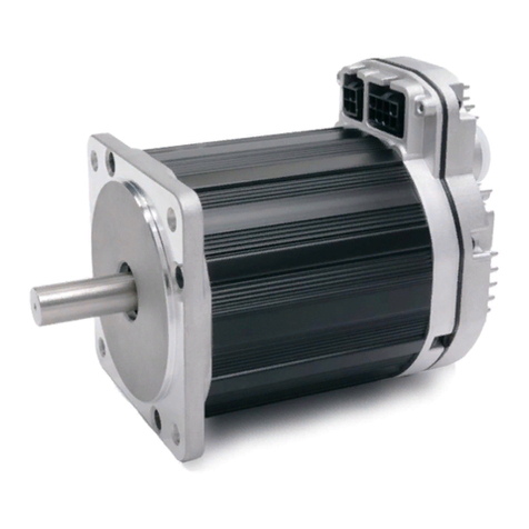
Hiteco QE-1F 7.5/6 24 63F NC CB Installation instructions

ELECTROSPINDLE
3-PHASE ASYNCHRONOUS MOTOR
MODEL: QE-1F 7.5/6 24 63F NC CB
CODE: 2 L0385638C
Rev. 00 (12/18)
•ASSEMBLY INSTRUCTIONS
•USER MANUAL
(TRANSLATION OF THE ORIGINAL INSTRUCTIONS)
SCM GROUP SpA HITECO
SS 258 Marecchia, 34
47826 Villa Verucchio*RN –Italia
tel. +3 0541 674 40
www.hiteco.net***


DOCUMENT INFORMATION
MANUFACTURER:
SCM GROUP Spa HITECO
ADDRESS:
SS 258 Marecchia 34
NAME
3-PHASE ASYNCHRONOUS MOTOR
BRAND
HITECO
MODEL:
QE-1F 7.5/6 24 63F NC CB
CODE:
29L0385638C
TYPE OF DOCUMENT:
•
ASSEMBLY INSTRUCTIONS
•USER MANUAL
(ORIGINAL INSTRUCTIONS)
DOCUMENT CODE:
90L0505599B
EDITION
00 (12/18)
RELEASED BY:
HITECO TECHNICAL DEPARTMENT


INDEX
THIS MANUAL CANNOT BE REPRODUCED IN WHOLE OR IN PART
1 Preliminary information .............................................................................................. 1
1.1 Machine identification 2
1.2 Intended use 4
1.3 Risks connected to using the product 4
1.4 Incorrect use that can be reasonably expected 5
1.5 Specific risks with electrospindle in maintenance 6
1.6 Aim of the manual 6
1.7 General warnings 6
1.8 Carrier and handling warnings 7
1.9 Installation warnings 7
1.10 Warnings for the assigned personnel 7
1.11 Maintenance warnings 7
1.12 Meaning of the symbols 8
1.13 Description of the safety signals and their location 8
1.14 Glossary 9
1.15 Warranty conditions 10
2 Technical specifications 1
2.1 Electrospindle lay-out 2
2.2 Mechanical specifications and electrospindle performance 3
2.3 Inverter speed parameter setting 5
2.3.1 Installation Parameters 6
2.4 Noise emission level 7
2.5 Main parts 8

INDEX
THIS MANUAL CANNOT BE REPRODUCED IN WHOLE OR IN PART
2.6
Device for locking and toolholder expulsion
9
2.7 Tool 10
2.8 Tool holder unit (taper + tool + clamping parts) 11
2.8.1 Max. working speed according to the tool size 12
2.8.2 Examples of determining the max machining speed 18
3 - Handling, storage and unpacking............................................................................. 1
3.1 Warnings 2
3.2 Packaging 2
3.3 Dimensions and weights 2
3.4 Handling 3
3.5 Unpacking 3
3.6 Storage 4
4 Installation ................................................................................................................... 1
4.1 Preliminary checks 3
4.2 Availability of auxiliary systems in the factory 3
4.3 Mechanical connections 3
4.3.1 Electrospindle support table 3
4.3.2 Securing the electrospindle 4
4.3.3 Positioning with electric fan air cooling 5
4.4 Compressed air connections 5
4.4.1 Air purity of the compressed air circuit 5
4.4.2 Compressed air connection points on the electrospindle 6

INDEX
THIS MANUAL CANNOT BE REPRODUCED IN WHOLE OR IN PART
4.4.3 Compressed air circuit 7
4.4.4 Pressurisation 9
4.4.5 Cleaning air jet of the tool holder taper 9
4.4.6 Tool with air flow (option) 10
4.5
Compressed air cooling
13
4.6 Hydraulic cooling circuit 14
4.6.1 Hydraulic connections 14
4.6.2 Cooling fluid 14
4.6.3 Hydraulic circuit 15
4.7 Electrical circuit 16
4.7.1 Basic connection (CB) 16
4.7.2 Power contacts layout 17
4.7.3 Signal contacts layout 19
4.7.4 Electrospindle wiring 20
4.7.5 Tool release manual command pushbutton
for BASIC connection (CB) 21
4.8 Circular connectors connection (CC) 22
4.8.1 Power contacts layout 23
4.8.2 Signal contacts layout 25
4.8.3 Electrospindle wiring 26
4.8.4 Tool release manual command pushbutton
for circular connectors connection (CC) 28
4.9 PLUG connection (PP) 29
4.9.1 Power contacts layout 30
4.9.2 Signal contacts layout 32
4.9.3 Electrospindle wiring 34

INDEX
THIS MANUAL CANNOT BE REPRODUCED IN WHOLE OR IN PART
4.9.4 Tool release manual command pushbutton
for PLUG connection (PP) 36
4.10 Encoder connection 37
4.10.1Encoder contacts layout 38
4.11 Two-voltage electrical connection (BT) Basic 39
4.11.1Terminal board electrical connection 39
4.12
Two-voltage electrical connection (BT) PP
42
4.12.1Terminal board electrical connection 43
4.13 Electrical power circuit 45
5 - General checks after the installation........................................................................ 1
5.1 Checks before starting up 2
5.1.1 Positioning 2
5.1.2 Compressed air connections 2
5.1.3 Electrical connections 2
5.1.4 Inverter programming 3
5.1.5 Checks at the first start 3
6 - Intended use and usage limits................................................................................... 1
6.1 Environmental Conditions 2
6.2 Running-in 2
6.3 Pre-heating 3
6.4 Sensors 3
6.4.1 Technical specifications of the inductive sensors 4
6.4.2 State of the electrospindle and output of the sensors S1, S2 and S5
(optional) 5

INDEX
THIS MANUAL CANNOT BE REPRODUCED IN WHOLE OR IN PART
6.4.3 Logical management of the sensors output 6
6.4.4 Sensor S3 output 7
6.4.5 Thermal alarm and its management 8
6.4.5.1 Technical specifications of the thermal alarm 8
6.4.6 Electric fan rotation 8
6.5 Electric fan 9
6.5.1 Technical specifications of the electric fan 9
6.5.2 Monitoring the electric fan 10
6.6 ENCODER (optional) 11
6.6.1 General description 11
6.6.2 Sin – Cos encoder (optional) 11
6.6.3 512 square wave encoder (optional) 13
6.6.4 1024 square wave encoder (optional) 14
7 Scheduled maintenance................................................................................................... 1
7.1 Checking the cleaning of the tool holder taper and of the conical
seating of the spindle spindle 3
7.2 Protection of the conical seating of the spindle spindle 5
7.3 Cleaning and lubrication of the HSK tool holder taper 6
7.4 Cleaning and lubrication of the HSK tool holder collet 7
7.5 Tool pull check 8
7.6 Compressed air circuit filters discharge 8
7.7 Connections check 8
7.8 Compressed air circuit filters replacement 8
7.9 Bearings 8

INDEX
THIS MANUAL CANNOT BE REPRODUCED IN WHOLE OR IN PART
8 Unscheduled maintenance......................................................................................... 1
8.1 Sensors replacement and adjustment 3
8.1.1 Access to the sensors 3
8.1.2 Position and description of the sensors units 4
8.1.3 Sensor units replacement 6
8.1.4 Diagrams for the adjustment of sensors units S1 and S2 (ISO) 7
8.1.5 Diagrams for the adjustment of sensors units S1 and S2 (HSK) 8
8.1.6 S1 sensor adjustment “tool clamped correctly” 9
8.1.7 S2 sensor adjustment “collet open” 12
8.1.8 S3 sensor adjustment “spindle rotation” 14
8.1.9 S5 sensor adjustment “piston at stroke end” (optional) 15
8.2 Electric fan replacement 16
9 - Decommissioning and scrapping ............................................................................. 1
9.1 Decommissioning 2
9.2 Scrapping 2
10 - Troubleshooting ....................................................................................................... 1
10.1 Fault – probable cause – possible solution............................................ 2

29L0385638C
EN
1 - Preliminary Information
THIS MANUAL CANNOT BE REPRODUCED IN WHOLE OR IN PART
Chap. 1 - Page
1/11
INDEX
1.1 Machine identification 2
1.2 Intended use 4
1.3 Risks connected to using the product 4
1.4 Incorrect use that can be reasonably expected 5
1.5 Specific risks with electrospindle in maintenance 6
1.6 Aim of the manual 6
1.7 General warnings 6
1.8 Carrier and handling warnings 7
1.9 Installation warnings 7
1.10 Warnings for the assigned personnel 7
1.11 Maintenance warnings 7
1.12 Meaning of the symbols 8
1.13 Description of the safety signals and their location 8
1.14 Glossary 9
1.15 Warranty conditions 10

29L0385638C
1 - Preliminary Information
EN
Chap
.
1
- Page
2/11
THIS MANUAL CANNOT BE REPRODUCED IN WHOLE OR IN PART
1.1 Machine identification
The plate shown in the figure contains the machine ID data: this must be provided every time one of our assistance
centres is contacted.
The following information is shown:
Name - ASYNCHRONOUS 3-PHASE MOTOR
Brand - HITECO
Model - for example: ELETM MG-2 9/6 15 I40
Code - for example: 29L0456651E
Kg - WEIGHT (Kg)
Main electromechanical data: frequency (Hz), voltage (V), current (A), power (kW).
The serial number, the month/year of machine production are shown on the electrospindle body, in the point
indicated in the figure. The serial number consists of 2 letters, followed by 4 numbers (see example in the figure).
Identification plate (example)
Serial number (example)

29L0385638C
EN
1 - Preliminary Information
THIS MANUAL CANNOT BE REPRODUCED IN WHOLE OR IN PART
Chap. 1 - Page
3/11
BARCODE, DO NOT REMOVE.
Barcode (example)

29L0385638C
1 - Preliminary Information
EN
Chap
.
1
- Page
4/11
THIS MANUAL CANNOT BE REPRODUCED IN WHOLE OR IN PART
1.2 Intended use
The electrospindle is a partly completed machinery designed to be incorporated in machines for machining light
alloys, wood and materials with similar physical specifications and fr professional use.
The electrospindle is not suitable for use in areas classified as potentially explosive atmospheres, according to the
Directive 99/92/EC.
The electrospindle:
- must be powered with sinusoidal electricity supplied by a static frequency converter or
inverter;
- it must be used only with tool holders and tools balanced in group in grade G2.5 at the maximum
operating speed or higher, according to the standard ISO 1940/1;
- it must be fitted exclusively with tool holders:
- HSK models: HSK tool holders with dimensions and tolerance according to DIN 69893;
- ISO models: ISO tool holders with dimensions and tolerance according to DIN 69871-1;
- meet all the specifications set out in chap. 2 paragraph 2.7;
The operator must select the rotation speed of the electrospindle so that it is LOWER :
- than the maximum rotation speed permitted for the tool;
- than the maximum rotation speed permitted for the tool holder;
- than the maximum speed of the electrospindle;
- than the maximum rotation speed permitted for the electrospindle set out in the table in chap. 2 paragraph 2.8.2
based on the material and size of the tool used.
The machine:
- must have an interlock between the electrospindle start function and the safety of the tool change
performed;
- must have an interlock between the tool change function and the actual braking of the rotating unit;
- must cut off the electrospindle power supply in case of alarm or emergency; the power supply
must be restored manually.
The manufacturer will in no way be responsible for faults caused to the electrospindle or the machine that it
is installed in, due to incorrect application or design choices.
1.3 Risks connected to using the product
HITECO does not know and cannot know the product installation methods, therefore the installer or the final
customer must carry out a risk assessment specifically for the installation method and type.
In any case the installer must guarantee that there is an adequate degree of protection against the risk of accidental
contacts with moving parts.
The installer and the user must also bear in mind other types of risk, in particular, those due to the entrance of
foreign bodies and conveying explosive, flammable or toxic gases at high temperature.
Moreover the risk inherent the maintenance operations must be considered, as the operations mus be carried out in
maximum safety conditions, with the product cut off and the certainty that the tool is stopped.
At the end of the choices made and based on the product installation method defined and applied by the installer
and/or customer, the definitive machine can be considered a finished machine, according to the machinery
directive. An overall risk assessment must be carried out a declaration of conformity must be drawn up, according
to attachment IIA of directive 2006/42/EC.

29L0385638C
EN
1 - Preliminary Information
THIS MANUAL CANNOT BE REPRODUCED IN WHOLE OR IN PART
Chap. 1 - Page
5/11
1.4 UNINTENDED USE REASONABLY EXPECTABLE
- Use exclusively tool holders that comply with the standards indicated in this manual.
- Check that the conical surfaces of the tool holder engage with the electrospindle, are clean and are not damaged.
In fact dirt and dents can compromise the perfect coupling between the tool holder and the electrospindle spindle.
Clean the tool holder as indicated in chap. 7 paragraph 7.1. If there are any dents replace the tool holder.
- Always use perfectly sharp tools.
- Tighten the tool correctly in the tool holder.
- Do not damaged and/or imbalanced tools. The specifications on the balancing grade of the tool unit (tool holder
taper+tool+fixing parts) are indicated in chap. 2 paragraph 2.8.
When using ting nuts and elastic collets to fix the tool in the tool holder, check that all the coupling surfaces are
clean and without dents.
- The operator must select the rotation speed of the electrospindle so that it is LOWER :
- than the maximum rotation speed permitted for the tool;
- than the maximum rotation speed permitted for the tool holder;
- than the maximum speed of the electrospindle;
- than the maximum rotation speed permitted for the electrospindle set out in the table in chap. 2 paragraph 2.8.2
based on the material and size of the tool used.
- Before starting and using the electrospindle check that the rotation speed is the one selected
previously.
- Never rotate the electrospindles with ISO or HSK tool taper without the tool inserted!
The feed speed of the machine axes on which the electrospindle is installed must be selected so that:
- it is suitable for the power available to the electrospindle;
- it is suitable for the requested degree of finish;
- doe not trigger dangerous vibrations on the machine and/or piece being machined.
- The compressed air circuit that feeds the electrospindle must be the one specified in chap. 4 paragraph 4.4.3.
Make sure that the solenoid valves have single outlets and not shared with other solenoid valves. The outlet fitted
on the solenoid valves must be able to guarantee a fast compressed air outlet and it be must be sized to ensure
that it is not blocked due to dirt buildup.
- Check that the pipes of the compressed air circuit are nit crushed.
- Do not place the electrospindle in areas classified as potentially explosive atmospheres as defined by directive
99/92/EC.
- It is absolutely forbidden to neutralise, remove, change or render inefficient
any safety, protection or control device of the individual parts and of the entire product.
- Do not insert hands, arms or any part of the body close to the moving parts.
- The product must not be used in potentially explosive atmospheres.
- Unauthorised operators must not eliminate any defects or faults in the operation of the product and/or
alter the type of operation and installation.
- At at end of any unscheduled intervention that required the removal of guards, barriers or other
protection, restore their operation before restarting the product, making sure that they are positioned correctly and
that they are effective.
- All the protection and safety devices must be maintained in perfect and efficient conditions. The
recommendation and danger warning plates must be kept fully operational and must not be removed.
- When troubleshooting any faults on the product adopt all the precautions described in the Instruction Manual,
designed to prevent injuries to people or damaging property.
- Remember to tighten every screw, nut or fixing ring nut of each mechanical part subject to adjustments or
setup.
- Before starting the product check that all the safety devices are installed and perfectly operational. If they are
not it must not be started and the internal safety manager or the head of department must be informed immediately.
- The operator must be supplied with the legally required Personal Protection Equipment (PPE).

29L0385638C
1 - Preliminary Information
EN
Chap
.
1
- Page
6/11
THIS MANUAL CANNOT BE REPRODUCED IN WHOLE OR IN PART
1.5 Specific risks with electrospindle in maintenance
To operate in safety on an Hiteco product installed on a machine refer to the
machine's manual.
- Before proceeding with any maintenance operation make sure that the electrospindle spindle
has stopped completely.
- Before proceeding with any maintenance operation disconnect the power cable and the
signal cable from the power supply.
1.6 Aim of the manual
This manual is an integral part of the product and must remain with the product. If it is not the product is missing
one of its essential safety requirements.
- This instruction manual is aimed at the following subjects:
- Transport, handling and unpacking personnel
- Personnel assigned to setting up the systems and installation site
- Installers
- Machine operators
- Maintenance personnel
- Personnel assigned to installing or using the equipment must be qualified and therefore have the necessary
technical knowledge to correctly interpret the safety standards and the use methods set out in this manual.
The warnings in this manual are designed to safeguard the safety of people exposed, against residual risks.
The instructions provide the indications on the most suitable behaviour for the correct use of the product, as
indicated by the manufacturer.
In order to prevent incorrect operations that could cause danger to people and/or damage the product it is important
to read an understand all the document ion supplied with the product.
The instruction manual indicates the manufacturer's intended use.
The instruction manual must be stored with utmost care and always be made available for consultation. If
necessary, make copies of the pages that will be used directly on the machine.
Even though the instructions in this manual are detailed, a certain knowledge of the machining procedure is
required to obtain the maximum performance.
HITECO reserves the right to make all changes it deems necessary, without warning or replacement.
1.7 General warnings
- Do not perform operations or manoeuvres unless you are completely certain of their effect.
If you have any doubts contact the closest technical support service or the manufacturer directly.
- The manufacturer shall not be responsible for any damage caused to the machine or property, in the
following cases:
- improper use
- use of unsuitable personnel
- incorrect assembly and installation
- defects in the system
- unauthorised changes or interventions on the machine
- use of non-original spare parts
- non compliance with the regulations set out in this manual
- exceptional events.

29L0385638C
EN
1 - Preliminary Information
THIS MANUAL CANNOT BE REPRODUCED IN WHOLE OR IN PART
Chap. 1 - Page
7/11
1.8 Carrier and handling warnings
Always check that the handling and transport equipment and machinery is suitable. Check the weight of the
electrospindle on the identification plate (see chap. 1 paragraph 1.1).
1.9 Preparation for Installation
- The installation must be carried out by qualified personnel.
- The parts of the control system, inverter and all the electrical, hydraulic and compressed air connections are the
responsibility of the installer. They must check the perfect operation of the whole system before starting the
equipment. If there are any doubts contact HITECO directly or an authorised support centre.
- The systems must be executed correctly before installing the machine.
- The electrospindle is a device designed to be inserted in other machinery, after having carried out the necessary
interventions and protections to remove the risks that can arise during the machining.
- When preparing the installation location take into account the space and work conditions in order to reduce as
much as possible noise, fatigue, discomfort and anything else that could affect the assigned personnel negatively.
- When deciding the installation location leave sufficient space for the control, maintenance, cleaning and removal
of material residue from machining waste.
- Place effective warning close to the machine to ensure that unauthorised personnel cannot operate close to the
work area necessary for the machining cycle.
- Provide adequate lighting of the work station to ensure the best working conditions for the assigned personnel.
1.10 Warnings for the assigned personnel
- The machine must be used with the adequate personal protection equipment.
- The machine must be used exclusively as described in this manual.
- The machine can only be used by personnel who have read the regulations
described in this manual.
- Check the process phases often and avoid at all cases, during machining, contact with the
sharp parts and moving parts.
- When disassembling and replacing tools, used adequate personal protection equipment (gloves.
- During the operation there are live parts. The incorrect access to these parts or
the non-compliance with the safety recommendations could generate a danger for people or the machine.
N.B.: The use of certain personal protection equipment may be necessary based on the type of material and
work conditions.
1.11 Instructions for maintenance
- Any maintenance operation must be carried out by qualified personnel, with the machine stopped and
disconnected from the electrical and compressed air supply.
- Always close all the cut off valves upstream of the machine.
- When cleaning painted parts do not use solvents or alcohol, as they could damage the
surface.

29L0385638C
1 - Preliminary Information
EN
Chap
.
1
- Page
8/11
THIS MANUAL CANNOT BE REPRODUCED IN WHOLE OR IN PART
1.12 Meaning of the symbols
GENERIC DANGER It indicates a procedure, activity or action that, if not carried out
correctly or complied with, can cause injuries to people.
SMB124
WARNING! It indicates a procedure, activity or action that, if not carried out
correctly or complied with, can damage or destroy completely
the product.
INFORMATION It indicates general information that must not be
ignored.
1.13 Description of the safety signals and their location
INFORMATION REQUIRED
Indicates that before using the machine, you must read the instruction manual
and understand all its parts. Symbol position: on the electrospindle
identification plate.
DANGEROUS ELECTRICAL CURRENT
Set the main electrical switch to zero and padlock it before performing
operations on the parts with this symbol.
Symbol position: on the electrospindle electrical connection
This manual suits for next models
1
Table of contents
