Hiten 2H User manual

VERTICALTURRETMILLINGMACHINE
OPERATIONMANUAL
Model:2H4H5H
Themachinehasbeeninspectedandfoundtobeuptothe
standard,thenapprovedforex‐factory.
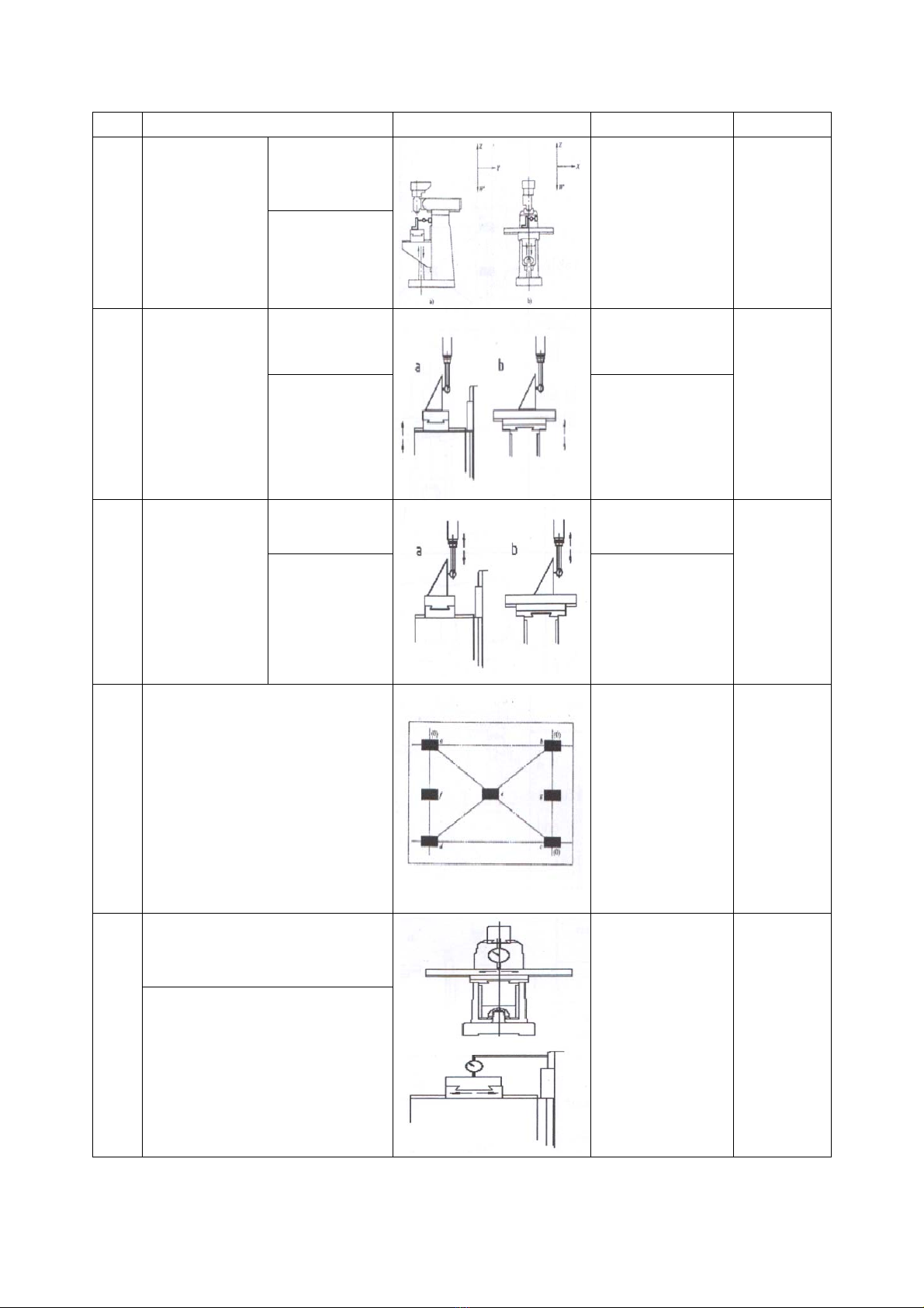
No.Inspectionitemfiguretolerancemeasured
G1
Straightness
ofknee
vertical
movement(W
axis)
a)inthecross
andvertical
surface(YZ)
Within0.025at
300arbitrary
length
measurement
b)ina
longitudinal
andvertical
surface(ZX)
G2
Squarenessof
uppersurface
oftableto
knee
movement
Rightandleft
direction
Per/0.025/300
Forwardand
backward
direction
0.025/300
G3
Squarenessof
vertical
movementof
thespindle
headwith
tablesurface
Rightandleft
directionPer0.020/125
Forwardand
backward
direction
0.020/125
G4Flatnessofworktable
0.040in1000
length,foreach
additional1000
lengthof
workingtable,
tolerancevalues
increasedby
0.005
G5
Parallelismofrightandleft
movementoftabletoits
uppersurface
0.02/300max.
0.04
Parallelismofforwardand
backwardmovementoftable
toitsuppersurface

G6Runoutofspindlea)0.01
b)0.01
G7
Mainspindle
taperhole
run‐out
Atfixedend
oftestbar0.01
Atpoint3000.02
G8
Squarenessof
uppersurface
oftableto
centrelineof
spindle
Rightandleft
directionPer0.025/300
Forwardand
backward
direction
0.025/300
G9Straightnessoftablecentralor
benchmarkTslot
Inany500
measuring
lengthis
0.010,the
maximum
tolerance0.030
G10
Parallelismofrightandleft
movementoftabletosideof
middleTslotoftable
0.015/300
max.0.04

G11
Squarenessofforwardand
backwardmovementoftable
tosideofmiddleTslotof
table
Per3000.02
G12
Parallelismofforwardand
backwardmovementof
overarmwithtablesurface
0.035/300
G13
Parallelismofleftandright
movementofswivelturret
withtablesurface
0.035

SKU HT-2H001 HT-4H002 HT-5H003
Operation Info
Max. Drilling Capacity (steel) 1-1/4" 1-1/4" 1-1/4"
Max. Drilling Capacity (lron) 1-1/2" 1-1/2" 1-1/2"
Max. End Milling Capacity 1" 1" 1"
Max. Face Milling Capacity 3" 3" 3"
Max. Distance Spindle to Column 17-29/32" 21-27/32" 21-27/32"
Max. Distance Spindle to Table 15-3/4" 18-7/8" 21-21/32"
Longitudinal Table Travel (X-Axis) 23-5/8" 29-15/16 33-7/8"
Cross Table Travel (Y-Axis) 12-19/32" 15-3/4" 15-3/4"
Knee Table Travel (Z-Axis) 15-3/4" 15-3/4" 17-23/32"
Ram Travel 11-13/16" 15-3/4" 15-3/4"
Spindle Travel 5" 5" 5"
Head Swivel (Left / Right) 90° 90° 90°
Head Tilt (Front / Back) 45° 45° 45°
Turret or Column Swivel 360° 360° 360°
Spindle Info
Spindle Taper R8 R8 R8
Number of Spindle Speeds 16 16 16
Spindle Speeds 80 - 5440 RPM 80 - 5440 RPM 80 - 5440 RPM
Quill Auto. Feed 0.0015, 0.003,
0.006 in./rev. 0.0015, 0.003,
0.006 in./rev. 0.0015, 0.003,
0.006 in./rev.
Table Info
Table size 9" × 42" 10" × 50" 10" × 54"
T-Slots 3 @ 2½ centers,
5/8" wide 3, @ 2½ centers,
5/8" wide 3, @ 2½ centers,
5/8" wide
X/Y-Axis Travel per Handwheel Revolution 0.2" 0.2" 0.2"
Z-Axis Travel per Handwheel Revolution 0.1" 0.1" 0.1"
Electrical
Power Requirement Three-phase
220V 60 Hz Three-phase
220V 60 Hz Three-phase
220V 60 Hz
Amps 10A 10A 10A
Horsepower 3 HP 3 HP 3 HP
Shipping
Packing Size (L x W x H) 56.3" x 56.3" x
78.7" 64.2" x 61" x
82.7" 67" x 63" x 86.6"
Net Weight 1984.5 lbs 2469.6 lbs 2822.4 lbs
Shipping Weight 2160.9 lbs 2668.05 lbs 3042.9 lbs

CONTENTS
CHAPTER1.SAFETYINFORMATION
■ 1‐1IMPORTANTSAFETYINFORMATION‐‐‐‐‐‐‐‐‐‐‐‐‐‐‐‐‐‐‐‐‐‐‐‐‐‐‐‐‐‐‐‐‐‐‐‐‐‐‐‐‐‐‐‐‐‐‐‐‐‐‐‐‐‐‐‐‐‐‐1
■ 1‐2SAFETYRULESDURINGAND/ORBEFOREOPERATION‐‐‐‐‐‐‐‐‐‐‐‐‐‐‐‐‐‐‐‐‐‐‐‐‐‐‐‐‐‐‐‐‐‐‐‐2
■ 1‐3SAFETYDURINGELECTRICALCONNECTIONORDISCONNECTION‐‐‐‐‐‐‐‐‐‐‐‐‐‐‐‐‐‐‐‐‐3
■ 1‐4DESCRIPTIONFORTHESAFETYFUNCTIONOFTHISMACHINE‐‐‐‐‐‐‐‐‐‐‐‐‐‐‐‐‐‐‐‐‐‐‐‐‐‐3
■ 1‐5SAFETYINSPECTION‐‐‐‐‐‐‐‐‐‐‐‐‐‐‐‐‐‐‐‐‐‐‐‐‐‐‐‐‐‐‐‐‐‐‐‐‐‐‐‐‐‐‐‐‐‐‐‐‐‐‐‐‐‐‐‐‐‐‐‐‐‐‐‐‐‐‐‐‐‐‐‐‐‐‐‐‐‐‐4
CHAPTER2.INSTALLATION
■ 2‐1SAFETYPRECAUTIONS‐‐‐‐‐‐‐‐‐‐‐‐‐‐‐‐‐‐‐‐‐‐‐‐‐‐‐‐‐‐‐‐‐‐‐‐‐‐‐‐‐‐‐‐‐‐‐‐‐‐‐‐‐‐‐‐‐‐‐‐‐‐‐‐‐‐‐‐‐‐‐‐‐‐‐5
■ 2‐2INSTALLATION/CLEANING‐‐‐‐‐‐‐‐‐‐‐‐‐‐‐‐‐‐‐‐‐‐‐‐‐‐‐‐‐‐‐‐‐‐‐‐‐‐‐‐‐‐‐‐‐‐‐‐‐‐‐‐‐‐‐‐‐‐‐‐‐‐‐‐‐‐‐‐‐‐6
■ 2‐3MACHINEDIMENSION‐‐‐‐‐‐‐‐‐‐‐‐‐‐‐‐‐‐‐‐‐‐‐‐‐‐‐‐‐‐‐‐‐‐‐‐‐‐‐‐‐‐‐‐‐‐‐‐‐‐‐‐‐‐‐‐‐‐‐‐‐‐‐‐‐‐‐‐‐‐‐‐‐‐7
■ 2‐4FOUNDATIONPLAN‐‐‐‐‐‐‐‐‐‐‐‐‐‐‐‐‐‐‐‐‐‐‐‐‐‐‐‐‐‐‐‐‐‐‐‐‐‐‐‐‐‐‐‐‐‐‐‐‐‐‐‐‐‐‐‐‐‐‐‐‐‐‐‐‐‐‐‐‐‐‐‐‐‐‐‐‐8
■ 2‐5POWERSUPPLY‐‐‐‐‐‐‐‐‐‐‐‐‐‐‐‐‐‐‐‐‐‐‐‐‐‐‐‐‐‐‐‐‐‐‐‐‐‐‐‐‐‐‐‐‐‐‐‐‐‐‐‐‐‐‐‐‐‐‐‐‐‐‐‐‐‐‐‐‐‐‐‐‐‐‐‐‐‐‐‐‐‐‐9
■ 2‐6INITIALSETTING‐‐‐‐‐‐‐‐‐‐‐‐‐‐‐‐‐‐‐‐‐‐‐‐‐‐‐‐‐‐‐‐‐‐‐‐‐‐‐‐‐‐‐‐‐‐‐‐‐‐‐‐‐‐‐‐‐‐‐‐‐‐‐‐‐‐‐‐‐‐‐‐‐‐‐‐‐‐‐‐‐‐10
CHAPTER3.OPERATION
■ 3‐1SWIVELTURRET‐‐‐‐‐‐‐‐‐‐‐‐‐‐‐‐‐‐‐‐‐‐‐‐‐‐‐‐‐‐‐‐‐‐‐‐‐‐‐‐‐‐‐‐‐‐‐‐‐‐‐‐‐‐‐‐‐‐‐‐‐‐‐‐‐‐‐‐‐‐‐‐‐‐‐‐‐‐‐‐11
■ 3‐2MOVERAMSLIDE‐‐‐‐‐‐‐‐‐‐‐‐‐‐‐‐‐‐‐‐‐‐‐‐‐‐‐‐‐‐‐‐‐‐‐‐‐‐‐‐‐‐‐‐‐‐‐‐‐‐‐‐‐‐‐‐‐‐‐‐‐‐‐‐‐‐‐‐‐‐‐‐‐‐‐‐‐‐‐11
■ 3‐3CLAMPINGTABLE,SADDLEANDKNEE‐‐‐‐‐‐‐‐‐‐‐‐‐‐‐‐‐‐‐‐‐‐‐‐‐‐‐‐‐‐‐‐‐‐‐‐‐‐‐‐‐‐‐‐‐‐‐‐‐‐‐‐‐‐12
■ 3‐4MAINPARTOFMILLINGHEAD(WITHSTEPPULLEYCONTROLLED)‐‐‐‐‐‐‐‐‐‐‐‐‐‐‐‐‐13
■ 3‐5MAINPARTOFMILLINGHEAD(WITHVARIABLESPEEDMOTOR)‐‐‐‐‐‐‐‐‐‐‐‐‐‐‐‐‐‐‐14
■ 3‐6MAINPARTOFMILLINGHEAD(WITHININVERTERCONTROLLED
VARIABLE‐‐‐‐‐‐‐‐‐‐‐‐‐‐‐‐‐‐‐‐‐‐‐‐‐‐‐‐‐‐‐‐‐‐‐‐‐‐‐‐‐‐‐‐‐‐‐‐‐‐‐‐‐‐‐‐‐‐‐‐‐‐‐‐‐‐‐‐‐‐‐‐‐‐‐‐‐‐‐‐‐‐‐‐‐‐‐‐‐‐15
■ 3‐7SPINDLESPEED(WITHSTEPPULLEYCONTROLLER)‐‐‐‐‐‐‐‐‐‐‐‐‐‐‐‐‐‐‐‐‐‐‐‐‐‐‐‐‐‐‐‐‐‐‐‐‐16
■ 3‐8SPINDLESPEED(WITHVARIABLESPEEDMOTOR&INVERTERCONTROLLERD
VARIAVLE‐‐‐‐‐‐‐‐‐‐‐‐‐‐‐‐‐‐‐‐‐‐‐‐‐‐‐‐‐‐‐‐‐‐‐‐‐‐‐‐‐‐‐‐‐‐‐‐‐‐‐‐‐‐‐‐‐‐‐‐‐‐‐‐‐‐‐‐‐‐‐‐‐‐‐‐‐‐‐‐‐‐‐‐‐‐‐17
■ 3‐9FINEHEADFEED‐‐‐‐‐‐‐‐‐‐‐‐‐‐‐‐‐‐‐‐‐‐‐‐‐‐‐‐‐‐‐‐‐‐‐‐‐‐‐‐‐‐‐‐‐‐‐‐‐‐‐‐‐‐‐‐‐‐‐‐‐‐‐‐‐‐‐‐‐‐‐‐‐‐‐‐‐‐‐18
■ 3‐10AUTOMATIONFEED‐‐‐‐‐‐‐‐‐‐‐‐‐‐‐‐‐‐‐‐‐‐‐‐‐‐‐‐‐‐‐‐‐‐‐‐‐‐‐‐‐‐‐‐‐‐‐‐‐‐‐‐‐‐‐‐‐‐‐‐‐‐‐‐‐‐‐‐‐‐‐‐‐18
■ 3‐11SPINDLESPEEDSELECTION(WITHSTEPPULLEYCONTROLLED)‐‐‐‐‐‐‐‐‐‐‐‐‐‐‐‐‐‐19
■ 3‐12SPINDLESPEEDSELECTION(WITHVARIABLESPEEDMOTOR)‐‐‐‐‐‐‐‐‐‐‐‐‐‐‐‐‐‐‐‐20
■ 3‐13SWINGMILLINGHEADFORWARD&BACKWARD‐‐‐‐‐‐‐‐‐‐‐‐‐‐‐‐‐‐‐‐‐‐‐‐‐‐‐‐‐‐‐‐‐‐21
■ 3‐14SWINGMILLINGHEADLEAF‐SIDE&RIGHT‐SID‐‐‐‐‐‐‐‐‐‐‐‐‐‐‐‐‐‐‐‐‐‐‐‐‐‐‐‐‐‐‐‐‐‐‐‐22

CHAPTER4.MAINTENANCE
■ 4‐1MILLINGHEADLUBRICATIONSYSTEM‐‐‐‐‐‐‐‐‐‐‐‐‐‐‐‐‐‐‐‐‐‐‐‐‐‐‐‐‐‐‐‐‐‐‐‐‐‐‐‐‐‐‐‐‐‐‐‐‐‐‐‐‐‐‐‐‐‐23
■ 4‐2AXIALLUBRICATIONSYSTEMX/Y/Z‐‐‐‐‐‐‐‐‐‐‐‐‐‐‐‐‐‐‐‐‐‐‐‐‐‐‐‐‐‐‐‐‐‐‐‐‐‐‐‐‐‐‐‐‐‐‐‐‐‐‐‐‐‐‐‐‐‐‐‐‐24
■ 4‐3LUBRICATIONSYSTEM‐‐‐‐‐‐‐‐‐‐‐‐‐‐‐‐‐‐‐‐‐‐‐‐‐‐‐‐‐‐‐‐‐‐‐‐‐‐‐‐‐‐‐‐‐‐‐‐‐‐‐‐‐‐‐‐‐‐‐‐‐‐‐‐‐‐‐‐‐‐‐‐‐‐‐‐‐‐‐25
■ 4‐4GIBADJUSTMENT‐‐‐‐‐‐‐‐‐‐‐‐‐‐‐‐‐‐‐‐‐‐‐‐‐‐‐‐‐‐‐‐‐‐‐‐‐‐‐‐‐‐‐‐‐‐‐‐‐‐‐‐‐‐‐‐‐‐‐‐‐‐‐‐‐‐‐‐‐‐‐‐‐‐‐‐‐‐‐‐‐‐‐‐26
■ 4‐5BACKLASHADJUSTMENT(XAXIS)‐‐‐‐‐‐‐‐‐‐‐‐‐‐‐‐‐‐‐‐‐‐‐‐‐‐‐‐‐‐‐‐‐‐‐‐‐‐‐‐‐‐‐‐‐‐‐‐‐‐‐‐‐‐‐‐‐‐‐‐‐‐‐‐‐27
■ 4‐6BACKLASHADJUSTMENT(YXIS)‐‐‐‐‐‐‐‐‐‐‐‐‐‐‐‐‐‐‐‐‐‐‐‐‐‐‐‐‐‐‐‐‐‐‐‐‐‐‐‐‐‐‐‐‐‐‐‐‐‐‐‐‐‐‐‐‐‐‐‐‐‐‐‐‐‐‐28
■ 4‐7CLOCKSPRINGREPLACEMENT‐‐‐‐‐‐‐‐‐‐‐‐‐‐‐‐‐‐‐‐‐‐‐‐‐‐‐‐‐‐‐‐‐‐‐‐‐‐‐‐‐‐‐‐‐‐‐‐‐‐‐‐‐‐‐‐‐‐‐‐‐‐‐‐‐‐‐‐‐29
■ 4‐8COLLETALIGNINGSCREWREPLACEMENT(R8)‐‐‐‐‐‐‐‐‐‐‐‐‐‐‐‐‐‐‐‐‐‐‐‐‐‐‐‐‐‐‐‐‐‐‐‐‐‐‐‐‐‐‐‐‐‐‐‐‐30
■ 4‐9ADJUSTINGSPINDLEBEARINGANDREPLACEBEARING(NT30#)‐‐‐‐‐‐‐‐‐‐‐‐‐‐‐‐‐‐‐‐‐‐‐‐‐31
■ 4‐10REMOVEMOTOR‐‐‐‐‐‐‐‐‐‐‐‐‐‐‐‐‐‐‐‐‐‐‐‐‐‐‐‐‐‐‐‐‐‐‐‐‐‐‐‐‐‐‐‐‐‐‐‐‐‐‐‐‐‐‐‐‐‐‐‐‐‐‐‐‐‐‐‐‐‐‐‐‐‐‐‐‐‐‐‐‐‐‐‐‐32
■ 4‐11DRIVINGEELTREPLACEMENT(WITHSTEPPULLEYCONTROLLED)‐‐‐‐‐‐‐‐‐‐‐‐‐‐‐‐‐‐‐‐‐‐‐33
■ 4‐12BRAKEDRUM&TIMINGBELTREPLACEMENT(WITHSTEPPULLEYCONTROLLED)‐‐‐33
■ 4‐13DRIVINGBELTREPLACEMENT(WITHSTEPVARIABLESPEEDMOTOR)‐‐‐‐‐‐‐‐‐‐‐‐‐‐‐‐‐‐‐34
■ 4‐14DRIVINGBELTREPLACEMENT(WITHVARIABLESPEEDMOTOR)‐‐‐‐‐‐‐‐‐‐‐‐‐‐‐‐‐‐‐‐‐‐‐‐‐‐35
■ 4‐15BRAKEDRUMREPLACEMENT(WITHVARIABLESPEEDMOTOR)‐‐‐‐‐‐‐‐‐‐‐‐‐‐‐‐‐‐‐‐‐‐‐‐‐‐35
■ 4‐16FEEDTRIPADJUSTMENT‐‐‐‐‐‐‐‐‐‐‐‐‐‐‐‐‐‐‐‐‐‐‐‐‐‐‐‐‐‐‐‐‐‐‐‐‐‐‐‐‐‐‐‐‐‐‐‐‐‐‐‐‐‐‐‐‐‐‐‐‐‐‐‐‐‐‐‐‐‐‐‐‐‐‐‐36
CHAPTER5.PARTSLIST
■ 5‐1HEADTOPHOUSINGASSEMBLYSTEPPULLEY/A001~A087‐‐‐‐‐‐‐‐‐‐‐‐‐‐‐‐‐‐‐‐‐‐‐‐‐‐‐‐‐‐‐‐38
■ 5‐2HEADTOPHOUSINGASSEMBLYFORVARIABLESPEED/VS001~VS155‐‐‐‐‐‐‐‐‐‐‐‐‐‐‐‐42
■ 5‐3HEADTOPHOUSINGASSEMBLYFORINVERTERCONTROLLEDVARIABLESPEED/EVS1
~EVS103‐‐‐‐‐‐‐‐‐‐‐‐‐‐‐‐‐‐‐‐‐‐‐‐‐‐‐‐‐‐‐‐‐‐‐‐‐‐‐‐‐‐‐‐‐‐‐‐‐‐‐‐‐‐‐‐‐‐‐‐‐‐‐‐‐‐‐‐‐‐‐‐‐‐‐‐‐‐‐‐‐‐‐‐‐‐‐‐‐‐‐‐‐‐48
■ 5‐4MACHINEHEADASSEMBLY/B001~B192‐‐‐‐‐‐‐‐‐‐‐‐‐‐‐‐‐‐‐‐‐‐‐‐‐‐‐‐‐‐‐‐‐‐‐‐‐‐‐‐‐‐‐‐‐‐‐‐‐‐‐‐‐‐‐52
■ 5‐5X.YAXISLEADSCREWASSEMBLY/D001~D028‐‐‐‐‐‐‐‐‐‐‐‐‐‐‐‐‐‐‐‐‐‐‐‐‐‐‐‐‐‐‐‐‐‐‐‐‐‐‐‐‐‐‐‐‐‐‐‐‐59
■ 5‐6BASICMACHINEASSEMBLY/2C001~2C133‐‐‐‐‐‐‐‐‐‐‐‐‐‐‐‐‐‐‐‐‐‐‐‐‐‐‐‐‐‐‐‐‐‐‐‐‐‐‐‐‐‐‐‐‐‐‐‐‐‐‐‐‐61
CHAPTER6.ELECTRICALDIAGRAM‐‐‐‐‐‐‐‐‐‐‐‐‐‐‐‐‐‐‐‐‐‐‐‐‐‐‐‐‐‐‐‐‐‐‐‐‐‐‐‐‐‐‐‐‐‐‐‐‐‐‐‐‐‐‐‐‐‐‐‐‐‐‐‐‐‐‐‐‐‐‐‐‐66

**INTRODUCTION**
THISMANUALHASBEENCAREFULLYPREPARED,PLEASESTUDYIT
THOROUGHLYBEFORETRYINGTOOPERATETHEMACHINE.
**AFEWMINUTESGIVENTOREADINGTHISMANUAL
CAREFULLY,COULDENSUREYOUACHIEVEMAXIMUMPERFORMANCE
FROMTHEMACHINE&REDUCETHERISKOFINJURYTOTHEOPERATOR
ORDAMAGETOTHEMACHINEORWORKPIECE.
EVERYEFFORTHASBEENMADEDURINGCONSTRUCTION&TESTINGTO
ENSURETHISMACHINEMEETSINTERNATIONALQUALITY&
PERFORMANCEREQUIREMENTS.WEWISHITSERVESYOUWELL.

1
CHAPTER1.SAFETYINFORMATION
1‐1IMPORTANTSAFETYINFORMATION:
A. Applicationofthemillingmachine
Themillingmachineisdesignedandconstructedforthecuttingofmetaland
similarmaterials.
Themachineisalongwithallthenecessarysafetyrequirements.Onlyfully
trained&fullyqualifiedoperatorsshouldbeallowedtooperatethismachine.
B. Prohibition:
‐Untrainedoperatorsareprohibitedfromusingthismachine.
‐Modificationsthatchangethefunctionorspecificationofthismachineis
prohibited.
‐Operationofthismachinebeforereadingthroughthisinstructionmanual,is
prohibited.
C. Airbornenoiselevel:
‐Theairbornenoiselevelduringoperationisabout70~75Db(A).
D. lighting:
‐Appropriatelightingmustbeprovided,accordingtolocalregulation.
‐Minimumlightingforthismachineis300LUX,iftherearenoanylocalother
localregulations.
E. Environment:
1. Ambientairtemperature:+41℉~+131℉infreeair,andtheaverageambient
airtemperatureoveraperiodof24hoursshallnotexceed+122℉
2. Humidity:30%~95%.
3. Altitude:upto1000mabovemeanseelevel.
4. Transportation&storagecondition:‐77℉~+131℉,andforshortperiodsnot
exceeding24hoursupto+158℉

2
1‐2SAFETYRULESDURINGAND/ORBEFOREOPERATION
A. Besuretheinstructionmanualarefullyunderstood.
B. Usesafetyprotectiveequipmentsuchassafetyshoes,goggles,clothes,etc.
C. Worktablenearthemachinemustbestrongenoughtopreventaccidentsandbe
surearticleswillneverslipoffthetablesurfacetointerferewiththeactof
machining.
D. Toolsandanyunnecessaryitemsarenotallowedtobeplacedonthemachine
table,movingparts,orsimilarlocations.
E. Beforeoperatingswitches,alwayscheckiftheswitchesaretherightonesand
nevertouchaswitchaccidentallyoritmaycausemalfunctionsordanger.
F. Donotoperateswitcheswithgloveson.Thiscouldcausemalfunctionsoreven
danger.
G. Donottouchswitcheswithwethands,anelectricshockcouldoccur.
H. Warmupthemachinebeforeuse,especiallythespindleandfeedingaxesby
runningthemfor10to20minutes.Itisveryimportantformaintainingmachine
accuracy.
I. Ifjobistobedonebytwoormoreoperators,thefunctionofeachmustbewell
known,whatactionwillbedoneandwhatdangermayoccur,beforethenext
stepistaken.
J. Toolsshouldconformtothemachine‘sspecifications,suchasdimensions,weight
andtypes.
K. Gripworkpiecessecurelytominimizemovementorvibrationbetweenworkpiece
andcuttingtooloritmayinjurepersonnel,ordamagethemachineorworkpiece.
L. Nevertouchtoolnoseandcuttingchipswithbarehands.
M. Nevertrytotouchaturningworkpieceorspindleinanyway.
N. Stopthemachinebeforereplacingaworkpieceandprovideplentyofdistance
betweenworkpieceandtooltoavoidimpactbetweenworkpieceandtoolduring
thechangeover.
O. Intheeventofpowerfailure,turnoffthemaincircuitbreakerimmediately.
P. Afterpowerfailureoranemergencystop,itisnecessarytoreturntoreference
pointofthethreeaxes.
Q. Donotchangeelectricalsettingsunlessnecessary.Ifsuchchangesare
unavoidable,recordtheoriginalvaluessothattheycanbereturnedtotheir
originalsettingsifneeded.
R. Beforereplacingafuseorelectricpart,turnoffthemachineandkeeparecordof
them,forfuturereference.
S. Ifunspecifiedlubricantisused,itmayresultinmalfunctionsordamagetothe
machine.
T. Limitswitches,proximityswitches,interlockmechanismsincludingfunctional
partsandothersafetydevicesshouldnotberemovedormodified.
U. Disposeoffiltermaterialandpossibleworkingfluidaccordingtothelocal
regulation.
V. Pleasekeeptheinstructionmanualnearthemachineorinapositioneasytobe

3
reachedbytheoperator,andkeepthemforavailable&ingoodconditionforuse.
W. Pleasealwaysquotethemachinemodelandserialnumberinorderforustodeal
withanyrequest,asquicklyaspossible.
X. Themachinesurfaceissmearedwithanti‐rustprotectionwhendelivered.It
shouldbecarefullycleaned&thensmearedwithprotectionoil.
1‐3SAFETYDURINGELECTRICALCONNECTIONORDISCONNECTION
A. Electricalconnection:
1. Acablewiththreewiresissuppliedtoconnectyourmachineinto3phase
powersupply.
2. Theexactpowersourcevoltage,frequency,andnumberofphaseshallbe
checkedaccordingtotheinstallationdiagramandcircuitdiagram.
3. Thecorrectdirectionsofspindleshouldbecheckedafterconnecting.
B. Electricaldisconnection:
1. Thedisconnectioniscarriedoutbyhand‐operateddisconnectingdevice,
whichisonthedoorofcontrolboxasanoptionorconnectedbeforethe
powersource.
2. Besuretodisconnectthismachinefrompowersource,whenyouwantto
stopthejobformaintenanceoradjustment.
C. Grounding:
Thegroundingofthismodeliscarriedoutbyconnectingtheyellow/green
terminalofsupplycabletothegroundingterminalofpowersource.Besureto
groundyourmachinebeforeconnectingmachinetopowersourceinanysituation.
WARNING!
DONOTDISCONNECTGROUNDINGTERMINALBEFOREDISCONNECTINGPOWER
SOURCE
D. Whereaportionofthemachineanditsassociatedequipmentischangedor
modified,mustbeapprovedbythemanufacturerfirst,andfollowingretestshall
becarriedoutinaccordancewiththeclausesofen60204‐1,1992edition:
‐Continuityoftheprotectivebondingcircuit.(SUBCLAUSE20.2)
‐Insulationresistancetests.(SUBCLAUSE20.3)
‐Voltagetests.(SUBCLAUSE20.4)
‐Functionaltests.
1‐4DESCRIPTIONFORTHESAFETYFUNCTIONOFTHISMACHINE
Thefollowingsafetyfunctionsareequippedwiththismachinebesuretocheckand
ensurethecorrectfunctionbeforeyoustarttooperateyourmachine:
A:Thehand‐operatedpowerdisconnectiondevice:
Itisconstructedtodisconnectmachinefrompowersourcewhentheoperatorintend
tostopoperationformaintenance,repair,and/orwhiletheendofwork.The

4
correctionisthatthedoorofcontrolcabinetcouldbeopenonlywhenthisswitchof
thisdeviceisswitchedoff,andafterthisdeviceisswitchedoff,itispossibletobe
lockedwithsomeappropriatelocking.assoonasthisdeviceisswitchedoff,noany
operationispossibleandtherewouldbenoanyelectricityonthecontrolcircuit
exceptthewringbeforethisdevice.
B.Theemergencystopdevice:
Itisconstructedtostopmachineasfastaspossiblewhileinemergencysituation.as
soonasthisdeviceisactuated,anymovementwillbestoppedinashorttime.after
theactuationofemergencybutton,thefurtheroperationispossibleonlywhenthis
buttonisdisengagedandtherestartkeyisactuated.Besuretocheckthatmachine
actionwillstopimmediatelyafterthisbuttonispushedandwillnotcauseanyaction
whenthisbuttonisdisengaged.
1‐5SAFETYINSPECTION
Toensuresafety,itisnecessarytodothefollowinginspectionsforthismachineafter
installation.
A. Checkifthetransportationprocedurehasinfluencedtheaccuracyandfunctions
ofthemachine.
B. Checkifthefoundationofthemachineisappropriate.
C. Checkifthefactoryhasthecorrectthunder‐preventingsystemunder25.The
machine’spowerswitchshouldalsohaveearthwiringconnected.
D. Usethemultitestertocheckifthethree‐phasevoltageisstableandphasesarein
order.
E. Checkifspindlerotationisnormal
F. Checkifthecontrolpanelfunctionandpushbuttonarefunctioning(including
indicatorlamp,loadandrpmmeter).
G. Checkemergencystopfunction
H. Checkifsafetyprotectionaccessoriesarefunctioningwell.
I. Checkifotheraccessories,includinghydraulicandpneumaticones,are
connectedwell(includingtransformeretc.).
J. Checkiftheoilamountindicatorandtheairpressureindicatorarenormal.
K. Makesurenoobstacleisaroundmachineandcontrolsystem.
L. Makesurenopersonnelisindangerousarea.

5
CHAPTER2.INSTALLATION
2‐1SAFETYPRECAUTIONS
1. Besuretheinstructionmanualisfullyunderstood.Mustfollowinstruction
manualtooperatemachinecarefully.
2. Theoperatorwithouttrainingorbeingauthorizedisprohibitedtooperatethis
machine.
3. Setallcoversinpositionbeforeoperation.
4. Usesafetyprotectiveequipmentsuchassafetyshoes,goggles,clothes,etc.and
donotwearglovesorornaments.
5. Mustnottouchrunningcutters.
6. Nevertrytotouchworkpieceorcleanchipswhilecuttersisrunning.
7. Keephead&handsclearfromrunningmachineparts.
8. Turnpoweroffbeforemaintenance.

6
2‐2INSTALLATION
METHOD1
Insert3/4 ” (whitworth)eye
boltintohole.Ensureboltis
fullysecuredbeforelifting.
Itisadvisabletoswivelhead
beforeliftingmachine.
METHOD2
Useropeslingasillustrated.
Insertpartsofsoftcloth
Betweenropeandmachine.
Itisadvisabletoliftthehead
beforeliftingthemachine.
CLEANING
1. Removerustpreventativebefore
movinganyslideways.
2. Thecoatingisbestremovedby
Usingparaffinappliedwithclean
rags.
3. Whenthecoatinghasbecome
Soft,removewithcleanrags.
4. Oilorgreasealllubricationpoints.

7
2‐3MACHINEDIMENSION
Unit:mm
ModelSpecifications2H(X6323)4H5H(X6325)5H(X6330)5H(X6333)
AOverallheight2006 (79”) 2235 (88”) 2130(84”)2180 (86”)
BOveralldepth1600 (63”) 2156 (85”) 2057(81”)
COverallwidth2156 (85”) 2540 (100”) 2235(88”)2970 (117”)
DMin.distance42 0 0
Max.distance405(16”) 405(18”)430(18‐1/2 ” )
EMin.distance0 0 0
Max.distance305(12”) 456(18”) 560(22”)
FMin.distance170(6‐3/4 ” ) 140 (5‐1/2 ” ) 108(4‐1/4 ” )
Max.distance482(19”) 609 (24”) 760(29‐7/8 ” )
GMin.distance228 (9”) 254 (10”) 285(11‐1/4 ” )
Max.distance 532(21”) 710 (28”) 895(35‐1/4 ” )
HMin.distance863(34”) 965 (38”) 965(38”)
Max.distance 1270 (50”) 1370 (54”) 1370(54”)

8
2‐4FOUNDATIONPLAN
Unit:mm
DIMENSION
MODELLAB
2H(X6323series)1500740520
4H5H(X6325series)1500889540
5H(X6330series)1570960540

9
2‐5POWERSUPPLY
A).Machinesuppliedwithelectricalbox
1. Checkandconfirmcorrectvoltagefromfactorypowersource.
2. Turnmachinemainpowerswitch“OFF”,connectmachinemainpowercable
andgroundwiretofactorypowersource.
3. Power“ON”machineandcheckmotorrotationdirection,ifitrotatesreverse,
switchmainpower2cablesconnectiontocorrectit.
B).Machinesuppliedwithoutcontrolpanel
1. Checkthemotorvoltagesagainstsupply.
2. Turnpower”OFF”,connectmainpowerandgroundwire,thenmachineis
ready.
3. Power“ON”machineandcheckmotorrotationdirection,ifitrotatesreverse,
switchmainpower2cablesconnectiontocorrectit.

10
2‐6INITIALSETTING
1. Ifthemachinewasdeliveredinacrate,theslidewayhandleshavebeen
takenoff.Theseshouldbere‐fitted.
2. Themachineheadwasturneddownforshippingpurpose,machinehead
mustbeturnedupbeforepositioning.
Howtoturnmachineheadup:
1) Loosen○
Ehexagonnutalittlebit,andturnmachinehead.
2) Onepersonholdmachinehead,andtheotherpersonturn○
Fhexagon
screwtoturnmachineheadup.
3. Tosetmillingheadsquaretotable(forhorizontalplane):
1) Anindicatormountedinaspindlenosetravellingina115MM(4.5”)90°
radus,thentighten○
Glockhandle.
2) Loosen○
Ehexagonnut(4PCS.),turn○
Fhexagonscrew,thenadjustthe
pointc&d.
4. Tosetmillingheadsquaretothetable(forcrossplane):
1) Anindicatormountedinaspindlenosetravellingina115MM(4.5”)90°
radius,thentighten○
Glockhandle.
2) Loosen○
Hadaptorlockingbolts(3PCS.),turn○
Iverticaladjustingworm
shaft,thenadjustthepointA&B.
NOTICE:X/Y/ZAXISARELOCKEDSEPARATELY,PLEASELOOSENRESPECTIVELOCKING
LEVER.

11
CHAPTER3.OPERATION
3‐1SWIVELTURRET
1. Usespannertoloosenthe4bolts.
2. Indextotherequiredsetting.
3. Tightenthe4bolts.
3‐2MOVERAMSLIDE
1. Usespannertoloosenthe2bolts.
2. Turnthehandletomovetheslide
tothedesiredposition.
3. Lockandtightenthe2bolts.
12
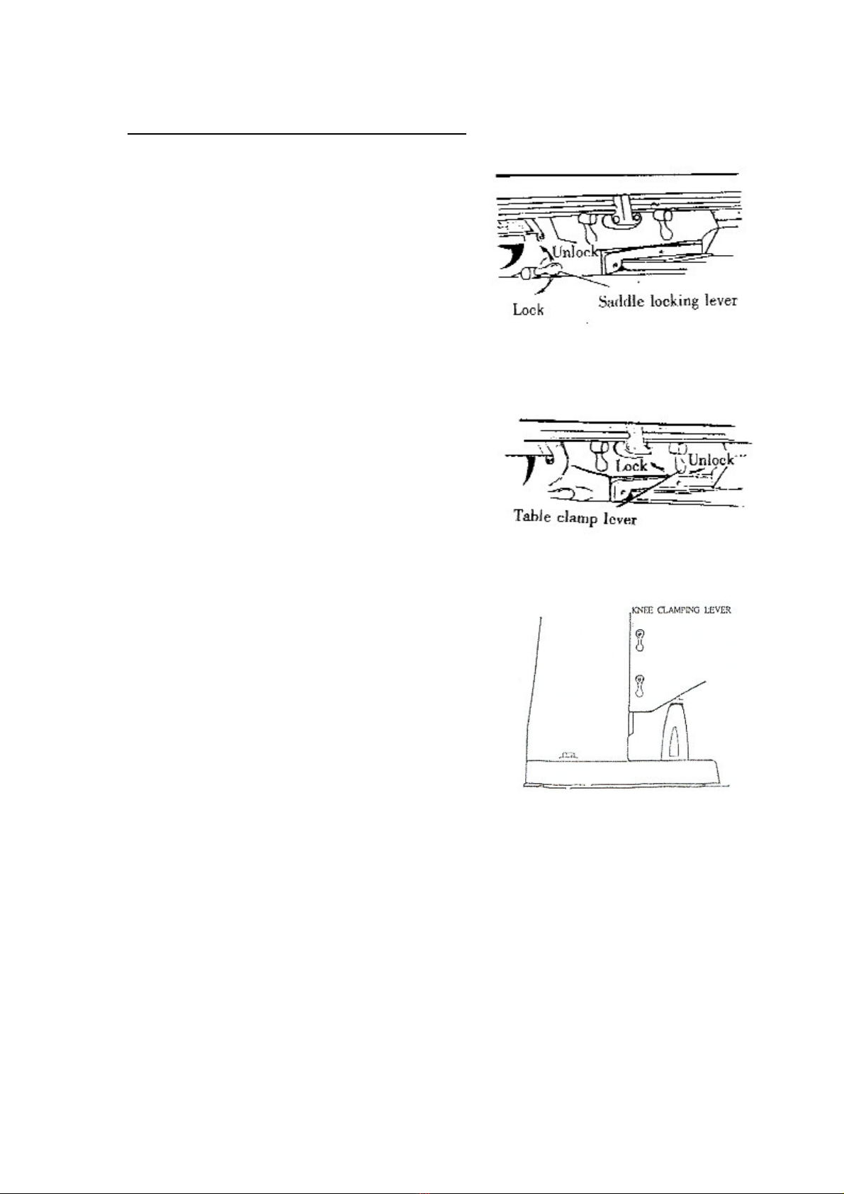
3‐3CLAMPINGTABLE,SADDLEANDKNEE
1. Whenmillingwithlongitudinal
Tablefeedonly,itisadvisableto
clampthekneetothecolumnand
thesaddletothekneeto
addrigiditytothese
membersandprovidefor
heaviercutswithaminimum
ofvibration.Thesaddle
lockingleverislocatedon
theleft‐handsideofsaddle.
2. Thetableclampleveris
locatedonfrontofsaddle
andshouldalwaysbe
clampedwhenlongitudinal
movementisnotrequired.
3. Thekneeclampinglever
isattheleftsideofthekneeand
shouldbedrawnupwardtoclamp
andwillnotlockthekneecompletely.
Leaveclampedatalltimesunlessusing
kneeinoperation.
This manual suits for next models
2
Table of contents


