© 2017 Glenair, Inc. CAGE Code 06324 Printed in U.S.A.
GLENAIR, INC. • 1211 AIR WAY • GLENDALE, CA 91201-2497
818-247-6000 • FAX 818-500-9912 www.glenair.com
8
601-118
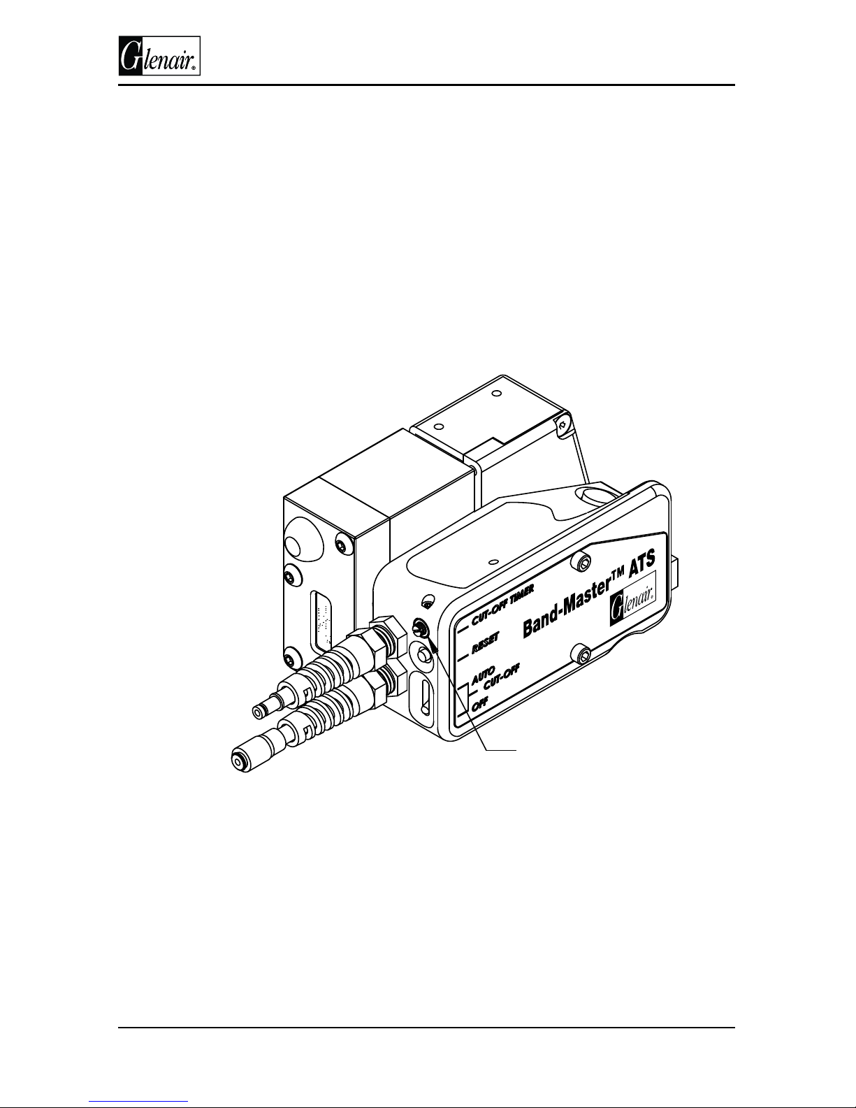
Operating Instructions
Counter features
(see gure 4)
1. Resettable Mileage counts
(top display)(see page 13)
2. Permanent life accumulate
counts (bottom display)
3. Counter display on switch
4. Power switch
Important notes:
Air supply line pressure is critical. 100-110 psi is required at the inlet port
of the regulator assembly to allow the tool to operate properly. For line
pressures less than 100 psi the tool must be tested for proper operation.
DO NOT ADJUST THE REGULATOR ON THE REGULATOR ASSEMBLY OVER
100 PSI
Do not over tighten the 5/16 inch hex locking collar for the regulator shaft,
damage may occur.
Improperly installed clamps may result in faulty shield termination and
insucient ground bonding.
Do not twist or force tool or cable assembly in any direction while installing
clamps.
Always install clamps perpendicular to the axis of the cable being terminated.
When clamping irregular shaped band platforms, choose a location of the
buckle where it is well supported on the bottom. A properly designed
backshell with a lip are essential when tensile loads may be expected.
To verify tension setting after the tool has been at rest for some time, actuate
the tool momentarily and conrm pressure setting on the digital pressure
gauge.
Glenair recommends that banding occur on an unxtured cable assembly.
Trying to band on a rmly xed surface may aect the applied forces and
interfere with the cut-o operation. The cut-o operation causes a rotation
of the band termination in order to aect a lock. Therefore, when performing
the banding operation on a xtured cable or device the operator MUST allow
the band tool to rotate slightly as the cut-o operation is performed.
012
123
Power Switch
Resettable
Count
Permanent
Count
Battery
Life
Figure 4