HiTT RX4000 User manual

H-ITT RX4000 instruction manual
H-ITT 420 Shearer Blvd Cocoa, Florida 32922
GENERAL:
The RX4000 communicates with all H-ITT RF clickers. There is no limit to the number of RF clickers that can be used with the RX4000.
The RX4000 has 31 RF channels that can be selected and are provided so that a classroom may have a unique RF channel to avoid
interference between another device in or about the classroom. The RX4000 is initially set to channel 07 to operate with H-ITT RF
clickers that are also initially set to channel 07. The RX4000 has selectable baud rates for communication to your PC. The default
setting is 19.2K baud. Higher Baud rates are available, but typically not needed. If higher baud rates are selected, the length of the USB
cable should not exceed 15 feet. There can be more than one RX4000 installed in a very large classroom or auditorium to provide
reliable communication with H-ITT’s remote clickers.
INITIAL SET-UP:
The RX4000 provides both USB and Serial communications ports.
Connect either of these ports to your classroom PC (do not connect both).
The USB connection provides power to the unit, so this is the only
connection needed. You will need to install a driver for the USB port in
your PC to communicate with H-ITT software (see below for connecting to
a computer). However, the RX4000 will power up as indicated below with
or without the drivers installed.
Attach the antenna to the SMA connector.
Power up the RX4000 by connecting the USB cable to a PC (that is
powered up) or connect the external power supply to the DC power jack.
The YELLOW indicator light will turn on and both the GREEN PC com and
RED RF com indicators will blink 4 times each. If the RF com indicator
blinks more than 4 times, and at a rapid rate, this can indicate that the RF
channel selected may have another fixed frequency transmitter operating on the same channel within the range of the base. If this
occurs, it is recommended that a different channel be selected using the internal set-up switch described below.
Connecting the RX4000 to your computer:
You can connect the RX4000 to your computer using the USB cable (which also provides power to the RX4000) or through a serial
connection (which requires an external power supply). The most common is the USB connection with the cable provided. Depending on
your operating system (Windows, Mac or Linux) you may need to install USB drivers for the software to properly handle the
communications from the RX4000 to your computer. USB drivers vary depending on your computers operating system; Windows or
Mac (Linux drivers are built in). Windows and Mac USB drivers are included on the CD supplied with the RX4000, click the link to
download/install the appropriate USB driver for your operating system. USB drivers are also provided at H-ITT.COM from the download
links where you will find instructions based on your operating system.
Installing Windows USB drivers may be confusing because when the RX4000 is first connected a “found new hardware” wizard will
pop-up. If you are connected to the Internet, this wizard can locate and install the proper drivers, but if not connected to the net the
wizard will return “drivers not found”. To simplify this, we recommend that you download the Windows USB driver “auto installer” to your
computer (either from the CD or from H-ITT.COM) and install drivers by double clicking the “auto installer”.exe file.
If the Serial port is used, the unit must have an external power supply connected, use H-ITT part number # AC-9VDC-US for standard
North American power outlets or AC-9VDC-INT for international power outlets.
TEST
With the RX4000 powered up, the RX4000 using a H-ITT RF remote (TX3000 or TX3100) by pressing a button (A/1 through J/0)
on an RF clicker and notice the GREEN PC Com light and RED RF com lights blink. This indicates the RX4000 is ready to operate.
Test with H-ITT software to make sure USB drivers are installed and the RX4000 is communicating with your computer:
Open H-ITT-CRS Acquisition program. On the initial screen of the Acquisition program under “Base Units and Port Settings” you will
see a new COM port appear when the base unit is connected with a USB cable. When a remote is activated, the remotes serial number
will appear under the Detected Responses columns.
Test the RX4000 installation: To ensure reliable communication between the RX4000 and remotes, go to the far corners of the
room (or from worst case seat positions) and verify the remotes green light turns on with a key press, and The RED and GREEN lights
on the RX4000 blink with each key press.
In most applications your H-ITT system is now ready to operate using the default settings, so once you verify that the RX4000 powers
up , and communicates with software, it is ready to use.
The following options of the RX4000 can be used if the application requires, but typically is not necessary.
USB Port
Serial Port
DC power jack
Power indicator
Antenna
PC com indicator
RF com indicator
Rev 1.0
Changing the RF channel and/or the RX4000 Baud rate.
The RX4000 has an internal programming switch block located on the circuit
board. Changing the default RF channel or baud rate requires accessing and
changing this programming switch.
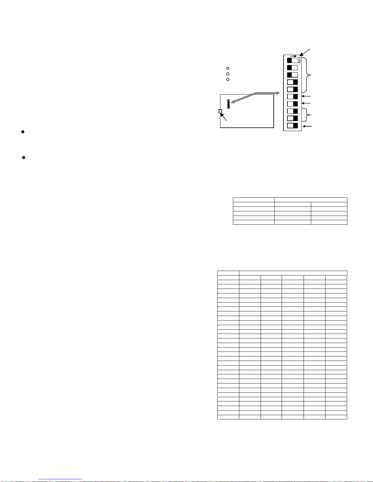
To access the internal set-up switch:
First, remove all com and power connections, then remove the snap-on cover
to access the set-up switch. To remove the cover, squeeze the bottom sides
near the ends, and lift the top cover, it will un-snap. With the cover removed,
Figure 1 shows the internal location of the 10-position DIP switch used for set
up. Switch positions 1 through 5 set the RF channel, (ref Table2). Switch
positions 6, 7 and 10 are factory use and should remain in the ON position
for normal operation. Switch positions 8 and 9 select the baud rate.
Some notes:
The default RF channel is 07. Changing the RF channel requires that the
remote transmitters used with the RX4000 “log on” to the selected channel.
Therefore you must inform users of the channel number you have selected so they can re-program their remotes to operate on the
same RF channel selected.
The default baud rate is 19.2K. USB cables over 15 feet should not be used when the Baud rate is set higher than 19.2K
Changing the BAUD RATE:
Table 1 shows the switch settings and resultant baud rate. The initial factory setting
is 19.2K baud.
DIP switch positions 8 and 9 are used to set the baud rate of the RX4000.
Reference figure 1 to locate the DIP switch, and table 1 for setting the desired baud
rate.
Changing the RF Channel:
Table 2 shows the numeric value of the 31 selectable channels. The
switch setting of all on should not be used. In order for the students’ clickers
to operate on the same RF channel as the RX4000, the selected RF
channel must be published, or otherwise be made known to the students in
the classroom where the RX4000 is being used. A description of Student
“log-in” for the classroom RF channel is provided in the clickers instruction
manual.
Note: the ON and
arrow direction may
show OFF and an
opposite arrow
Switch 10 is reserved
and must be in the ON
p
osition
1
2
3
4
5
6
7
8
9
10
Switch positions 1
through 5 select the
RF channel.
Switches 6 and 7 are
reserved and must
be in the ON position
Switch positions 8 and 9
select the baud rate
Circuit board,
reference location
for the10 position
DIP switch
ANTENNA
Switch settings shown
are the factory default:
RF channel is 07
Baud rate is 19.2K
Normal mode
FIGURE 1
DIP SWITCH #
BAUD RATE #9 #8
19.2K ON ON
38.4K ON OFF
57.6K OFF ON
115.2K OFF OFF
TABLE 1
DIP SWITCH #
Channel #5 #4 #3 #2 #1
01 ON ON ON ON OFF
02 ON ON ON OFF ON
03 ON ON ON OFF OFF
04 ON ON OFF ON ON
05 ON ON OFF ON OFF
06 ON ON OFF OFF ON
07 ON ON OFF OFF OFF
08 ON OFF ON ON ON
09 ON OFF ON ON OFF
10 ON OFF ON OFF ON
11 ON OFF ON OFF OFF
12 ON OFF OFF ON ON
13 ON OFF OFF ON OFF
14 ON OFF OFF OFF ON
15 ON OFF OFF OFF OFF
16 OFF ON ON ON ON
17 OFF ON ON ON OFF
18 OFF ON ON OFF ON
19 OFF ON ON OFF OFF
20 OFF ON OFF ON ON
21 OFF ON OFF ON OFF
22 OFF ON OFF OFF ON
23 OFF ON OFF OFF OFF
24 OFF OFF ON ON ON
25 OFF OFF ON ON OFF
26 OFF OFF ON OFF ON
27 OFF OFF ON OFF OFF
28 OFF OFF OFF ON ON
29 OFF OFF OFF ON OFF
30 OFF OFF OFF OFF ON
31 OFF OFF OFF OFF OFF
TABLE 2
MOUNTING THE RX4000.
Before mounting the unit, connect the antenna to the screw-on SMA connector on the end of the RX4000. DO NOT WRENCH or
OVERTIGHTEN the antenna, hold the antenna in the desired position and tighten the knurled section.
The RX4000 can be simply set on a table top, or permanently mounted to a wall using the swivel mount supplied which screws into the
threaded mounting hole on the back of the RX4000. Position the antenna based on how the unit is going to be mounted. Tests show
the range is optimized when the unit is wall mounted with the antenna pointing up.
For best performance:
1. The antenna should be vertical, or pointing up.
2. Avoid setting the unit on a metal table, or housing it in a metal type podium.
3. Mount the unit so it has a clear line-of-sight to the seats in the classroom.
Using multiple RX4000 base units in a large room.
In general, connecting multiple RX4000 base units within range of each other (where one remotes signal is received by multiple base
units) will not affect system performance. The remotes signal (i.e. students response) will always be accepted and processed (i.e. sent
to the computer) by all RX4000 base units that received the signal. H-ITT’s software provides for duplicate transmissions so the
students “answer” is received and processed correctly. However the remotes “green light” acknowledgement may be affected. Typically
if a student does not get the “green light” they will try again, in which case the rare occasion of acknowledgement interference will not
occur, and they get the green acknowledgment light on the second input. Or if you are displaying the ID grid or marquee the student will
see their response has been accepted via the projector screen.
There are several options to install and connect multiple RX4000 within a classroom. First you need to consider which H-ITT response
software you will be using:
H-ITT CRS software can accept multiple com ports simultaneously, so multiple RX4000’s connect to any open com port.
H-ITTShow software requires all responses come into a single com port, so multiple RX4000’s can not be used.
The classroom dimensions or layout may affect how you locate and connect multiple RX4000 units.
The following provides some guidelines, however it is recommended that you contact H-ITT support for specific installations when
multiple RX4000 base units are necessary.
Connecting a long data cable to a second RX4000:
From the RX4000 serial data port connect a female DB9 to RJ45 converter (part # AC-ADPT-F) to the serial connector. Then route
CAT5 cable from the RX4000 to the computer and use a CAT5 to serial adapter (part # AC-ADPT-M) to connect to the computer. You
can directly connect this to a serial port, or use a serial to USB converter cable. H-ITT does not sell these converter cables, but most
any commercially available serial to USB converter will work. H-ITT has tested CAT5 data connections as described above for
distances over 300 feet at 19.2K baud. CAT5 cables in various lengths, and CAT5 couplers (to link cables together) are available from
H-ITT. The serially connected RX4000 will also need the power adapter.
Connecting long USB cables:
You may connect USB cables over the typical 16 foot limit when the serial baud rate is set at 19.2K. Using a 16 foot USB cable (part#
AC-USB-16) with a USB extender cables (part# AC-USB-EX16) you can connect two RX4000 base units more than 100 feet apart.
Depending on the classroom layout (relative to the computers location) this may be a good option.
RX4000 Technical specifications
Length 7.07” (179.6mm)
Width 4.92” (125.0mm)
Height 1.40” (35.6mm)
Weight 9.3 oz. (263 grams)
USB Port USB-B
Serial Port DB9
Baud rate 19.2K, 39.4K,57.6K, 115.2K
DC power USB or 7 to 15VDC, 100mA.
RF carrier 2.4Ghz ISM band
RF channels 31
RF data 2Mbit, NRZ format
RF Range 300 feet open field**
FCC ID UH9RX4000
** Indoor range may be significantly less, range is
specified under controlled open field testing with TX3100..
Contact info:
Additional information regarding installation, applications and software can be found at
http://www.h-itt.com. You can e-mail [email protected] or call toll free 1-888-322-0089 for
technical assistance with any problems installing or using your H-ITT product.
FCC ID: UH9RX4000
THIS DEVICE COMPLIES WITH PART 15 OF THE FCC
RULES. OPERATION IS SUBJECT TO THE FOLLOWING
TWO CONDITIONS: (1) THIS DEVICE MAY NOT CAUSE
HARMFUL INTERFERENCE, AND (2) THIS DEVICE MUST
ACCEPT ANY INTERFERENCE RECEIVED, INCLUDING
INTERFERENCE THAT MAY CAUSE UNDESIRED
OPERATION.
THE MANUFACTURER IS NOT RESPONSIBLE FOR ANY
RADIO OR TV INTERFERENCE CAUSED BY
UNAUTHORIZED MODIFICATIONS TO THIS EQUIPMENT.
SUCH MODIFICATIONS COULD VOID THE USER’S
AUTHORITY TO OPERATE THE EQUIPMENT.
Compliant
H-ITT, LLC
420 Shearer Blvd
Cocoa, FL 32922


