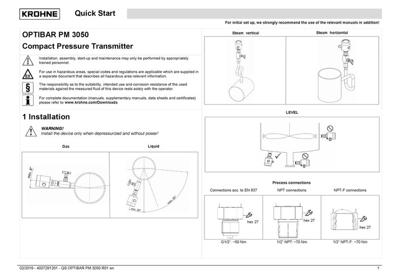
Star Meter KPE 9039G User manual

Installation instructions
CYYZ92 Exquisite Pressure Transmitter
星仪传感器
STAR METER
星仪传感器
24小时服务热线:400-600-4496 执行标准JB/T 10726-2007www.star-sensor.com
1
版号23.06.27
DANGER!
The transmitter adopts diffused silicon oil filled core, and improper
use will cause explosion accidents. To ensure safety, it is strictly
prohibited to measure oxygen.
DANGER!
This product is not explosion-proof, and its use in explosion-proof
area will cause serious personal injury and material loss.
!
!
a) After unpacking, check whether the documents and accessories
are complete according to the packing list.
Packing documents: one copy of operation manual.
One product certificate.
A warranty card.
b) When receiving the product, please check whether the package is
intact, and check whether the transmitter model and specification are
consistent with the product you choose.
c) Observe whether the transmitter is damaged due to transportation
for proper treatment.
d) The user is expected to keep the "warranty card" properly and do
not lose it, otherwise it cannot be returned to the factory for free
maintenance!
Unpack
Identification
Precautions for use
Summary
Safety guidance
These installation instructions contain important information on how to
use the transmitter correctly. The transmitter installer shall
carefully read the installation instructions before operating the
transmitter. In case of further understanding or special problems,
which are not described in detail in this operation manual, please
contact our company to obtain necessary information.
Please pay attention to the warning signs on the instructions!
Operators must strictly follow the safety instructions in the
installation instructions. In addition, occupational safety rules,
accident prevention guidelines, national installation standards and
engineering specifications must be observed.
Please keep this instruction properly and store it in a convenient
place near the transmitter.
The copyright of these installation instructions is protected. The
installation instructions of this version are written according to the
functions that can be realized by the corresponding product during
printing, and describe the product functions and operation steps as
detailed and complete as possible. If you find mistakes, you are
welcome to criticize and correct them. The company is not responsible
for the possible wrong description and possible consequences.
– reserve the right to modify the technical parameters –
Icon description
Danger! – A dangerous situation that could result in death or
serious injury.
Warning! – A potentially hazardous situation that could result in
death or serious injury.
Be careful! – A potentially hazardous situation that may result
in minor injury.
Reminder! – A potentially hazardous situation that may cause
personal injury.
Tips! – Tips and information to ensure trouble free operation of
the equipment.
User
Warning! These installation instructions are for technicians.
Limitation of liability
If the transmitter is damaged due to non-compliance with the operation
and installation instructions, improper use, self modification and
destruction, the company will not be liable for compensation and will
not provide warranty service.
!
!
!
!
!
model
range
output
power supply
accuracy
protect
Product number
Product certification
Wiring definition
PRESSURE Sensor
St ar Me ter
model:
:
:
:
accuracy :
protect :
Tel:400-600-4496
Opening
Select the opening position
according to the medium, with gas
at the top and liquid and steam
at the side or bottom.
It is recommended to install a pressure stop valve before the
pressure measuring point to facilitate the maintenance and disassembly
of the transmitter. In addition, it can reduce the pressure impact
during the initial installation of pressure measurement.
Installation precautions
After the pressure in the pipeline stabilizes, slowly open the
stop valve to start measurement.
In the hydraulic system, pay attention to the upward installation
of the pressure interface of the equipment (for gas discharge).
If the transmitter is installed in a harsh site and will encounter
dangerous damage such as lightning stroke or overvoltage, we recommend
that the user carry out lightning stroke and overvoltage protection
between the distribution box or power supply and the transmitter.
In order to avoid liquid flowing along the cable, causing liquid
accumulation at the waterproof joint or entering the junction box,
a U-shaped ring shall be configured between the threading box and the
pressure transmitter as shown in the figure, and the bottom of the
U-shaped shall be lower than the pressure transmitter. It is considered
that sufficient length of electric cable shall be reserved for
maintenance and replacement.
A pulse buffer is installed inside the sensor. If the liquid
contains particles, the pressure hole may be blocked. Installing the
sensor in a vertical position can effectively avoid the blockage of
the pressure hole. After the pressure tap hole is blocked, the pulse
buffer can be removed with a 2.5 hexagonal wrench, cleaned and then
reassembled( Do not use hard objects to poke the pressure sensing
film inside the pressure hole during disassembly)
Try to install it in the place with small temperature gradient
change.
Warning!
The equipment must be installed without pressurization and power supply.
!
Install
Do not weld the base with pressure
transmitter! The deformation of the
base caused by welding shall be
avoided, and the waste slag shall be
cleaned to avoid scratching the
measuring diaphragm( (accessories to
be purchased separately)
PWarning!
Do not measure media with incompatible materials in contact with the
transmitter.
! No modifications or changes can be made on the equipment.
! Handle with care and do not throw it at will. Please do not use
brute force when installing the transmitter.
! This product belongs to weak current equipment, which must be
laid separately from strong current cables, and shall be wired in
accordance with relevant national wiring standards (GB / t50312-2016).
Ensure that the power supply voltage meets the power supply
requirements of the transmitter. Ensure that the high pressure of the
pressure source is within the range of the transmitter;
During pressure measurement, pressurize and relieve pressure
slowly to avoid instantaneous increase to high pressure or decrease to
low pressure;
Please do not disassemble or touch the diaphragm when using, so
as not to damage the product.
!
fuel damper
Installation steps for connection with clamp or KF
The thread length of the
pressure transmitter must be
greater than the thread depth of
the base to ensure the effective
sealing of the end gasket.
The thread length of the
pressure transmitter must be
less than the thread depth of
the base to ensure effective
sealing of the root gasket.
Raw tape or sealant is used.
After locking, a small part of
the thread of the pressure
transmitter is surplus.
-Select appropriate sealing accessories according to the measured medium
and input pressure
-Put the seal into the installation position of the corresponding
connection
-Place the clamp connection or KF connection in the center with sealing
device
-Then lock the hoop
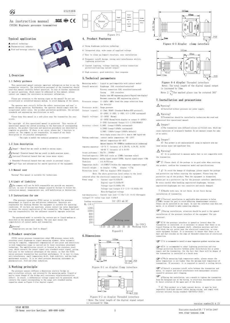
-Use a wrench to tighten the transmitter from the hexagonal nut at the
bottom of the transmitter to avoid directly turning the upper part of
the equipment and causing the disconnection of the connecting line.
The recommended installation torque is as follows:
Recommended
installation
torque (nm)
55~60
40~45
30~35
20~30
15~16
Interface
type
G1/4
G1/2
7/16UNF
1/2NPT
1/4NPT
1/8NPT
Interface
type
M27*2
M20*1.5
M14*1.5
M12*1.5
M10*1.0
Recommended
installation
torque (nm)
30~35
45~50
16~20
2~3TFFT
2~3TFFT
2~3TFFT
Installation torque
Note: tfft is the number of turns the tool is tightened after
hand tightening
Installation steps for threaded connections
-Select appropriate sealing accessories and sealing positions according
to the measured medium and input pressure
Installation steps for flange connection
-Select appropriate sealing accessories according to the measured
medium and input pressure(e.g. gasket)
-Place the seal between the equipment flange and the counter flange
-Install the equipment on the corresponding flange connection through
4-8 groups of bolts (according to the flange model)
Installation steps for connection of pagoda mouth or fast interface
-Check whether the size of air pipe and interface match
-After the air pipe is directly inserted into the interface, pull it
slightly by hand to check the reliability, that is, the connection is
completed
-Ensure that the sealing surface connected to the equipment is smooth
and flat
Pedestal
Face seal
Root seal
Thread seal
Transmitter
valve
Welded base

星仪传感器
STAR METER
接线示意
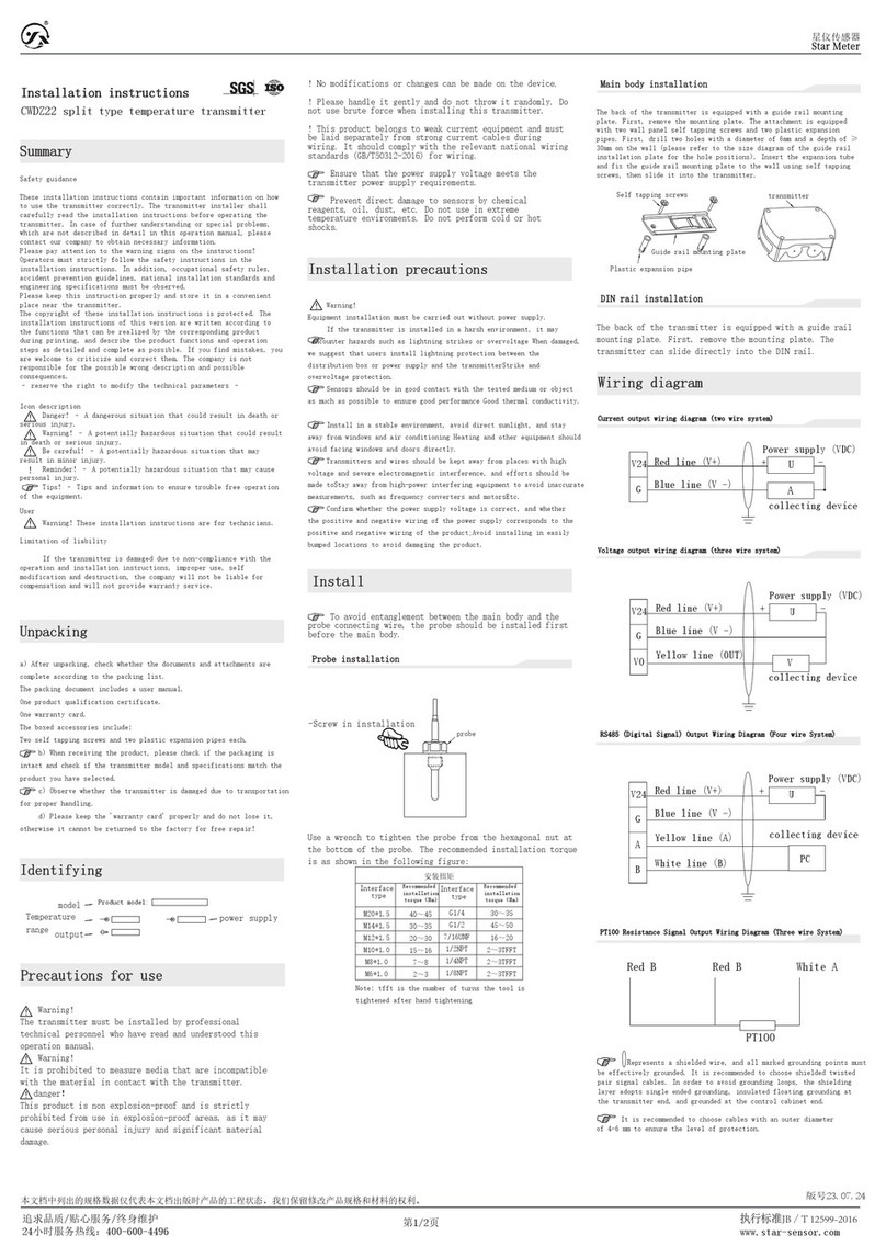
Represents a shielded wire, and all marked grounding points must
be effectively grounded. It is recommended to choose shielded twisted
pair signal cables. In order to avoid grounding circuits, the shielding
layer adopts single ended grounding, insulated floating grounding at
the pressure transmitter end, and grounded at the control cabinet end.
The transmitter casing is grounded by default, so it is required
that the on-site equipment be effectively grounded. If the on-site
equipment cannot be grounded, the indicated grounding point must be
effectively grounded.
wire
星仪传感器
24小时服务热线:400-600-4496 执行标准JB/T 10726-2007www.star-sensor.com
2
星仪传感器制造有限公司
Star sensor manufacturing Co., Ltd
Tel:400-600-4496
www.star sensor.com
厂址:燕郊经济开发区 天山国际创业基地 20号
Star MeterR
更多资料请扫码
前往官网获取
Disassembly and assembly steps of aviation plug
(without connecting wire)
12
3
4
a) Rotary lock nut and
compression bolt
c) Connect the wiring at the wiring terminal according to the wiring
diagram, restore it after wiring, and lock the compression bolt.
b) Separate the components
Lock nut
Subject
Terminal block
Hold down bolt
Hold down ring
Rubber ring
The user must ensure that the outer diameter of the cable used is
within the allowable range of the ferrule. In addition, ensure that
the cable is firmly installed in the ferrule without gap. The locking
diameter of the compression bolt is 4 ~ 5mm.
Be sure to install the socket correctly and properly to ensure the
degree of protection.
Warning!
a) Before startup, the user must check whether the transmitter is
installed correctly and whether there is obvious damage.
Warning!
b) The transmitter must be started and operated by professional
technicians who read and understand this operation manual.
Warning!
c) The transmitter is only applicable to the working conditions
that meet the technical requirements!
EMC statement
Applicable Directive: electromagnetic compatibility Equipment Directive
2014 / 35 / EU.
CE marking indicates that the product meets the requirements of applicable
EU standards.
The user must ensure that the whole equipment meets all use standards.
First start-up
!
!
!
Common fault analysis and troubleshooting
If the fault phenomenon does not fall within the above scope,
please contact our after-sales department,
400-600-4496
Fault phenomenon
·The transmitter
has no output signal
·When the differential
pressure is constant,
the output jumps irregularly
·When the transmitter is not
connected to the pressure,
the corresponding output value
is incorrect
·The transmitter output is
inconsistent with the measured
differential pressure
·Incorrect supply voltage
·Excessive external load
·Mechanical overload caused by
overvoltage
·Compliance with power supply scope
·Adjust external load
·When the transmitter is not
connected to the pressure,
the corresponding output value
is incorrect, and the transmitter
does not work in its required
environment
·Observe the humidity and
temperature allowed by the
environment
·The transmitter is not grounded
·Strong RF interference on site
·Shielded cable not used
·Use shielded cables and the
shielding layer is grounded
·The transmitter is reliably
connected with the earth
·Transmitter not powered
·Wiring error
·Power the transmitter correctly
according to the wiring diagram
Cause analysis Solution
Disassembly and after sales
Warning!
When disassembling the transmitter, ensure that the pressure source
and power supply of the transmitter have been disconnected to avoid
accidents caused by medium ejection;
During the warranty period, the products are detected by our
technicians as quality problems, and the company shall bear all
maintenance costs;
Warning!
Please clean up the residual media before returning, especially the
substances harmful to human health, such as corrosive, toxic,
carcinogenic or radioactive substances;
Please keep the warranty card and certificate, and return with the
product during maintenance;
If the transmitter fails, please contact our after-sales service.
After confirming the problem, you need to send the transmitter back to
our company for maintenance. Please attach the following information:
Description of site environment;
Fault phenomenon;
Receiving address and contact information;
Maintenance and cleaning
No maintenance is required to maintain the pressure transmitter.
Maintenance may only be performed by the manufacturer.
Before cleaning, the pressure transmitter needs to be relieved
and powered off.
Wipe the transmitter surface with a soft damp cloth.
!
!
Adjustment
maintain
Wrong detergent
Correct detergent
-Clear water
-Traditional detergent
-Using the wrong detergent will damage the label of the product.
-Do not use irritant cleaners.
-Do not use harmful or sharp sanitary ware.
-Do not use abrasive rags or sponges.
clean
Cleaning products
Zero and full scale drift may occur during the service life of the
transmitter. If the above phenomena occur after long-term use, it is
recommended to send the transmitter back to our company for calibration
to ensure high accuracy.
Transportation, storage and transportation
The transmitter shall be packed in a strong carton (wooden case
is required for large instruments). It is not allowed to move freely i
n the carton. It shall be handled with care and rough loading and
unloading is not allowed. The storage location shall meet the
following conditions:
a) Rain proof and moisture-proof.
b) Free from mechanical vibration or impact.
c) Temperature range - 30 ~ 70 ℃.
d) The relative humidity shall not be greater than 90% (no condensation).
e) The environment does not contain corrosive gases.
21
34
red
yellow
blue
white
ID Two wire three wire
1/red Power supply+ Power supply+
2/yellow OUT+
3/blue Power supply- Power supply-
4/white
Aerial insertion straight head strip line
21
34Note: Lock wire diameter 4-5mm
Aerial insertion straight head
ID Two wire three wire
1/red Power supply+ Power supply+
2/yellow OUT+
3/blue Power supply- Power supply-
4/white
21
34
Aviation elbow
Note: Lock wire diameter 4-5mm
ID Two wire three wire
1/red Power supply+ Power supply+
2/yellow OUT+
3/blue Power supply- Power supply-
4/white
21
34
Aerial insertion elbow strip line
red
yellow
blue
white
ID Two wire three wire
1/red Power supply+ Power supply+
2/yellow OUT+
3/blue Power supply- Power supply-
4/white
ID Two wire three wire
1/red Power supply+ Power supply+
2/yellow OUT+
3/blue Power supply- Power supply-
4/white
red
yellow
blue
white
Direct outgoing line
Current output wiring diagram (two wire system)
transmitter
P
Blue line (V-)
Red line (V+)
collecting device
Power supply (VDC)
Pressure
input
U
+-
A
Voltage output wiring diagram (three wire system)
transmitter
P
Red line(V+)
Blue line(V-)
Yellow line(OUT)
Pressure
input
V
U
+-
collecting device
Power supply (VDC)
Other Star Meter Transmitter manuals
Popular Transmitter manuals by other brands

Air Monitor
Air Monitor AUTO-purge III Installation, operation and maintenance manual
Vega
Vega VEGABAR 81 operating instructions
Dwyer Instruments
Dwyer Instruments CDT Series Installation and operating instructions

Comrex
Comrex ACCESS manual
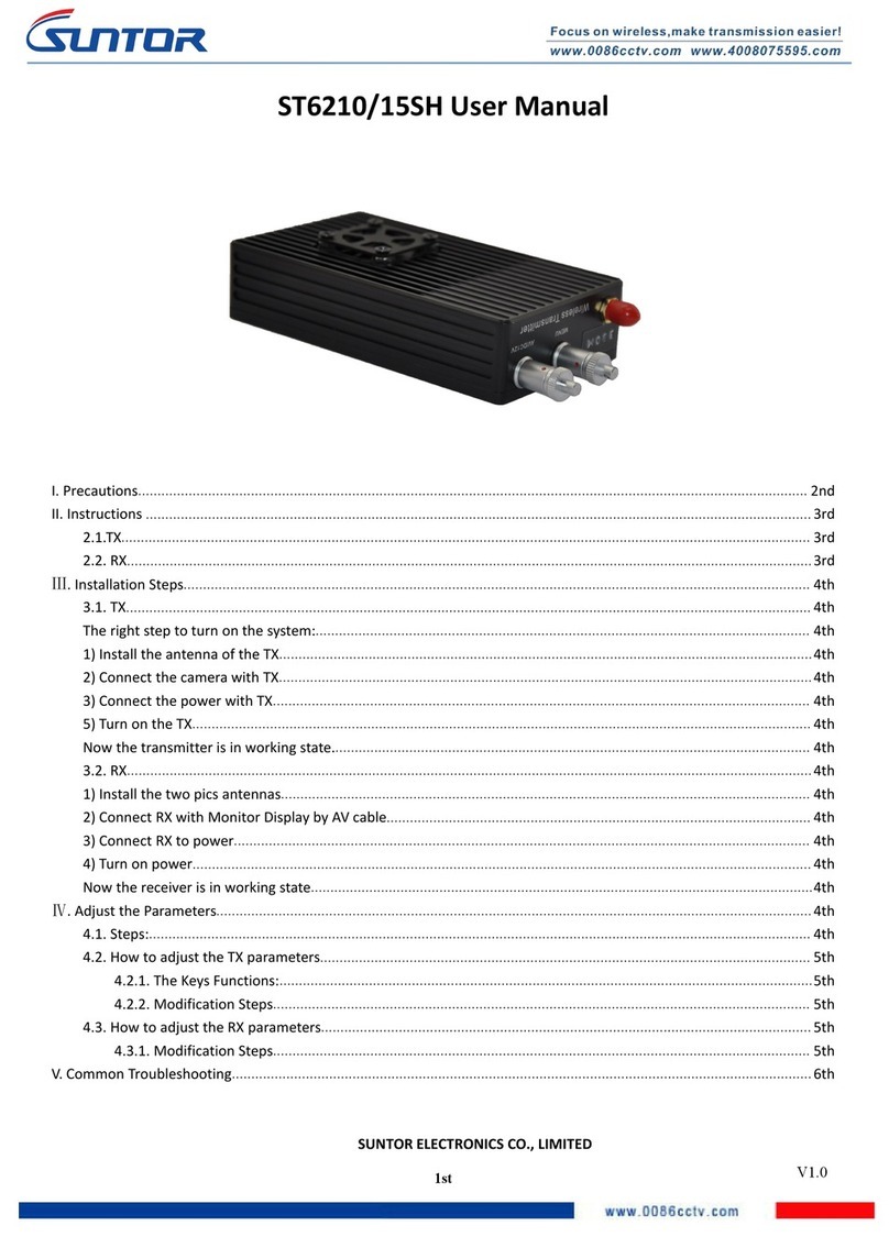
Suntor
Suntor ST6210SH user manual
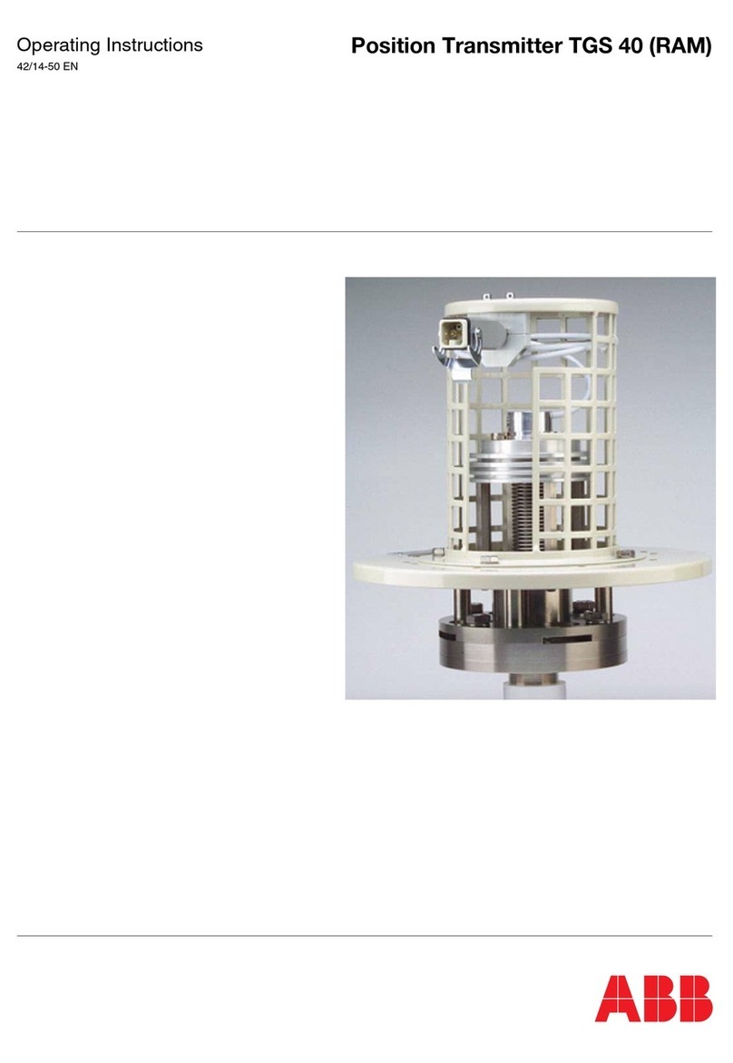
ABB
ABB TGS 40 operating instructions
