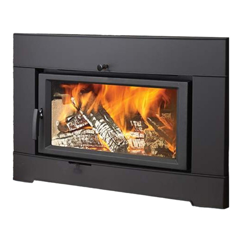
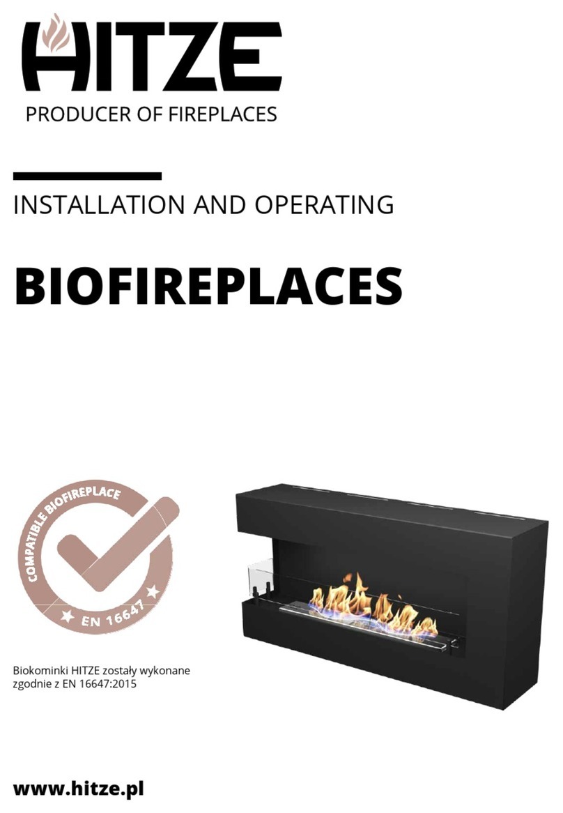
HITZE CUBO 700 Specification sheet

Last update: 10.11.2020
BEFORE USING THE PRODUCT FOR THE FIRST TIME, READ THE OPERATION
AND INSTALLATION MANUAL
OPERATION AND INSTALLATION MANUAL
FIREPLACE CASSETTE
CUBO
In accordance with the requirements of the Ecodesign Directive in the EU Member States:
"This product can not be used as a basic source of heating"

WWW.HITZE.PL
FIREPLACES | STOVES | BIOFIREPLACES | GARDEN HEATERS| ACCESSORIES
2
Table of contents
1. GENERAL INFORMATION....................................................................................................................................3
1.1 Safety.............................................................................................................................................................3
2. INTENDED USE OF THE CASSETTE ......................................................................................................................4
3. TECHNICAL DATA................................................................................................................................................6
4. STRUCTURE AND OPERATION OF THE INSERT ...................................................................................................8
5. TRANSPORT, ASSEMBLY AND INSTALLATION OF THE INSERT..........................................................................10
5.1 Transport.....................................................................................................................................................11
5.2 Recommendations concerning the floor: ...................................................................................................11
5.3 Chimney duct ..............................................................................................................................................12
5.3.1 Connection of the chimney ducts: .........................................................................................................12
5.4 Ventilation of the insert:.............................................................................................................................14
5.5 Installation of the insert..............................................................................................................................15
5.5.1 To ensure the correct installation..........................................................................................................15
5.5.2 General recommendations concerning the housing .............................................................................15
5.6 Connecting the hot air distribution system. ...............................................................................................16
5.7 Connecting the fan system..........................................................................................................................18
6.1 Getting ready for the start-up.....................................................................................................................20
6.2 Lighting the fireplace...................................................................................................................................21
7 USE ...................................................................................................................................................................22
7.1 Types of fuel................................................................................................................................................22
7.2 Refuelling: ...................................................................................................................................................22
7.3 Keeping the glass pane clean ......................................................................................................................23
7.4 Operation in adverse weather conditions and in the first period of use....................................................24
7.5 Removal of ash............................................................................................................................................24
7.6 General comments......................................................................................................................................24
8 MAINTENANCE .................................................................................................................................................25
8.1 Periodic cleaning of the fireplace................................................................................................................26
9 TROUBLESHOOTING .........................................................................................................................................26
10. NAMEPLATE......................................................................................................................................................28
11. INSPECTION RECORDS......................................................................................................................................29

WWW.HITZE.PL
FIREPLACES | STOVES | BIOFIREPLACES | GARDEN HEATERS| ACCESSORIES
3
INTRODUCTORY INFORMATION
Dear Customer,
Thank you for buying Hitze product!
Natural heating –these words perfectly reflect the philosophy of HITZE brand. In line with this philosophy, we
produce fireplaces and stoves fired with wood or wood pellets, i.e. the raw materials which are the least harmful
for the environment. Using a state-of-the-art technology, we have created innovative solutions offering modern
designs and high heating efficiency.
Our products have been designed to provide you with trouble-free operation and cosy warmth!
Before installing and connecting the fireplace insert, it is absolutely essential to become familiar with the Operation
and Installation Manual and check if all components are included.
The information contained in the Operation and Installation Manual is crucial for ensuring the correct functioning
of the fireplace insert, and thus eliminating the risk of damage and accidents caused by improper use.
In the case of doubts or operation-related problems, contact your purchase point or the Manufacturer.
NOTE:
This device must not be used by children.
Never leave your children or animals unattended when the fire is burning or when the fireplace is still hot.
Danger of burns (the glass and parts of the fireplace installation can be very hot).
In order to improve the product, the Manufacturer reserves the right to make changes in drawings, photographs
and descriptions or to modify the parameters of equipment without notice at any time.
The Operation and Installation Manual may not be copied as a whole or in part without prior consent of the
Manufacturer. Please make sure that the Operation and Installation Manual is stored out of reach of children.
If the Operation and Installation Manual is destroyed, lost or damaged, contact your purchase point or the
Manufacturer and provide the identification data of your device to obtain a replacement copy.
1. GENERAL INFORMATION
1.1 Safety
Compliance with the Manual is essential for ensuring the correct functioning of the fireplace insert and avoiding
damage and accidents caused by improper use.
1.1.1 Please observe the following safety rules:
before installing the insert or performing any maintenance work on it, make sure that you have read and
understood the Operation and Installation Manual;
the fireplace insert should be installed at the most convenient location and in conformity with the
applicable construction and fire prevention laws;
installation, maintenance and operation control activities may only be performed by qualified specialists;
the device may only be used in accordance with its intended purpose;
it is absolutely necessary to provide the installation site with appropriate ventilation and air intake sources;
a clothes dryer may be placed at least 1.5 m away from the insert (to minimize the risk of a fire);

WWW.HITZE.PL
FIREPLACES | STOVES | BIOFIREPLACES | GARDEN HEATERS| ACCESSORIES
4
check the permissible load carrying capacity of the substructure (floor, ceiling) at the intended location of
the insert (taking into account the total weight of the insert and its encasing);
provide an appropriate chimney installation to ensure safe operation (e.g. chimney made from non-
combustible materials with poor heat-absorbing properties);
avoid installation in rooms with B type gas devices, hoods (with or without exhaust), heat pumps, collective
ventilation conduits or multiple flue pipes; the insert must not be fitted in the vicinity of the staircase or
rooms with appliances capable of creating negative pressure;
avoid direct contact with the insert (it becomes very hot during use) and wear suitable protective
equipment (protective clothing or heat-resistant gloves);
install the insert in a room equipped with appropriate firefighting equipment and all utilities, including air,
water, electricity and smoke outlets;
if you encounter any problems, please contact your point of purchase or the Manufacturer (and always
request original spare parts for repairs);
check and periodically clean the combustion gas outlet pipe in accordance with the applicable provisions of
law;
if the device is sold or lent to another user, make sure to enclose the Operation and Installation Manual.
1.1.2 Never:
lean on the fireplace insert or climb onto it;
use the appliance in the event of fault or malfunctioning;
place flammable materials closer than 1.5 m to the fireplace;
light the fire with flammable materials or burn waste in the fireplace.
use a fireplace insert equipped with fans without fans switched on, this may damage the cassette.
1.1.3 The manufacturer is released from civil or criminal liability in the case when:
the insert is not used in accordance with the Operation and Installation Manual;
the fireplace insert is modified or its parts are replaced with non-original parts in an authorized manner
(any such modification or replacement immediately renders the guarantee null and void);
incorrect installation or improper maintenance (non-compliant with the Operation and Installation Manual)
lead to injuries or damage to property.
2. INTENDED USE OF THE CASSETTE
The fireplace cassette, in contrast to the typical insert, serves to adapt the existing open fireplace to the fireplace
with a closed furnace without its disassembly. The cassettes can be used as independent heat sources or used in
the air heating systems of the building. Due to the construction, they can only be burned with wood.
The PN-EN 13229: 2002 standard classifies the cassette hearth as 1c, with manual fuel supply, closed door and
allows the insert to be installed into the recess. Cubo is a fireplace with periodic combustion

WWW.HITZE.PL
FIREPLACES | STOVES | BIOFIREPLACES | GARDEN HEATERS| ACCESSORIES
5
1. encasing of the insert; 2. body of the insert; 3. door handle; 4. air adjustment lever;; 5. door; 6. flue;
Fig. 1 CUBO insert - general scheme

WWW.HITZE.PL
FIREPLACES | STOVES | BIOFIREPLACES | GARDEN HEATERS| ACCESSORIES
6
3. TECHNICAL DATA
CUBO insert
CUBO 800
8
4-10
2,2
85
1,206
158
150
740x481
127
230; 50
400
Recommended seasoned hardwood (beech, birch,
hornbeam)
Between 12 and 20%
CUBO 700
8
4-10
2,4
85
0,891
170
150
640x481
114
230; 50
350
Unit
[kW]
[kW]
[kg]
[%]
[g/m3]
[⁰C]
[mm]
[mm]
[kg]
[V; Hz]
[mm]
Symbol
P
Pog
B
η
CO13
tśr
Dcz
Sz
mk
U
lp
Parameters
Nominal power
Heating load range
Maximum fuel loading mass
Heating efficiency
CO emission (at 13% O2)
Average flue gas temperature
Flue pipe diameter
Glass dimensions
Weight
Power supply of the cassette
Maximum log length/logs diameter
Fuel type
Fuel humidity
Tab. 1. Technical data of CUBO

WWW.HITZE.PL
FIREPLACES | STOVES | BIOFIREPLACES | GARDEN HEATERS| ACCESSORIES
7
Fig. 2. Basic dimensions of CUBO fireplace cassettes
Dimensions
[mm]
CUBO inserts
CUBO 70
CUBO 80
A
700
800
B
540
540
C
535
535
D
470
470
E
587
587
Z
460
480
Zcz
150
150
Zd
100
100
Tab. 2. Fireplace cassettes CUBO dimensions

WWW.HITZE.PL
FIREPLACES | STOVES | BIOFIREPLACES | GARDEN HEATERS| ACCESSORIES
8
4. STRUCTURE AND OPERATION OF THE INSERT
Fig. 3. CUBO fireplace cassette
The fireplace cassette consists of encasing 1, body 2and front 12. The body is made of 3 mm thick P265GH
boiler steel. The front of the insert consists of steel door made of special profile, heat resistant glass pane and a
handle 10. The door is screwed to the body of the insert. The combustion chamber 5is lined with AKUCERAM 6on
the bottom, side walls and back wall. The primary air supply takes place in 3 ways: through a special channel
located in the front part 14 behind the cover 8and 9bottom channel 16 or rear channel 17, regulated by a throttle
lever.
Throttle adjustment is done by moving the lever forward or backward. In the maximally retracted position,
the air supply to the afterburners and openings on the inclined surface 15 is cut off, and in the maximally extended
position the maximum air supply is open.
The air used to burn off fumes is realized by two systems. In the first system, the air enters the combustion
chamber through the holes located under the door, and then flows through the channel and comes out through
the holes located on the inclined surface of the combustion chamber 15. In the second system, the air goes behind
the AKUCERAM ceramic concretes located on the rear wall of the combustion chamber and comes out through the
holes of the afterburner 4located in AKUCERAM. The air curtain has been designed to keep the glass clean when
burning fuels. The secondary air continuously between the housing and the body (above the door), through the
connection, blows out the air deflector 11 and goes on the glass.
Above the combustion chamber is a plate called deflector 3. The deflectors form a convection channel to
increase heat recovery. During combustion, the exhaust gases flow around the walls of the combustion chamber
and deflectors, get into the exhaust duct 13 and pass through the pipe to the chimney.

WWW.HITZE.PL
FIREPLACES | STOVES | BIOFIREPLACES | GARDEN HEATERS| ACCESSORIES
9
In the front of the cassette, under the floor of the combustion chamber, there are two blowing fans 7(only
with fans). The fans draw and push the air through a special channel (space between the body and housing). The air
flowing around the cassette is heated and get out back into the room. The fans are designed to increase the
amount of radiated heat into the room and protect the fireplace system from overheating. The fans start and stop
automatically when the temperature in the cassette reaches a certain value. The fans are powered by 230V
electricity.
CUBO cross-section depending on the method of assembly.
CUBO cassette with lower primary air intake. Armed
with a set of fans increasing the heating power of the
insert and equipped with a hot air curtain that improves
the functioning of the DGP system mounted from the
top of the cassette, forcing the air to flow through the
DGP system.
CUBO cassette with lower primary air intake. Armed
with a set of fans increasing the heating power of the
cassette. The fans also ensure that the warm air is
distributed more quickly In the room.

WWW.HITZE.PL
FIREPLACES | STOVES | BIOFIREPLACES | GARDEN HEATERS| ACCESSORIES
10
CUBO cassette with lower primary air intake. Without
set fans assembly. Cooling is done by gravity. The
heated air is lighter and flows naturally upwards,
bringing in fresh, cooler air.
CUBO cassette without external air intake. Without set
fans assembly. Cooling is done by gravity. The heated
air is lighter and flows naturally upwards, bringing in
fresh, cooler air.
5. TRANSPORT, ASSEMBLY AND INSTALLATION OF THE INSERT
The device is compliant with the PN-EN 13229:2002 standard and has a CE certificate.
Before assembling, installing and using the fireplace insert, read the Operation and Installation Manual carefully and
follow the instructions contained in it. It will ensure safe and efficient operation of the fireplace. Non-compliance
with this Operation and Installation Manual may invalidate the guarantee and put the user at risk of injury or loss of
life.
The product must be assembled, installed and used in accordance with the national and local laws and standards,
including in particular:

WWW.HITZE.PL
FIREPLACES | STOVES | BIOFIREPLACES | GARDEN HEATERS| ACCESSORIES
11
Regulation of the Minister of Infrastructure of 12.04.2002 Dz.U. [Polish Journal of Laws] No. 75, item 690
amended on 07.05.2004 Dz.U. [Polish Journal of Laws] No. 109, item 1156;
PN - B –03406 Standard: 1994 Heating engineering. Calculated heat demand;
PN –89 / B –10425 Standard: Flue pipes, combustion gas ducts and ventilation ducts made from bricks;
PN –78 / B –03421 Standard: Ventilation and air conditioning. Parameters for calculating indoor air;
PN-EN 13229:2002 Standard “Inset appliances including open fires fired by solid fuels. Requirements and
test methods”.
The fireplace insert must be installed by a qualified person or company and commissioning checks must be
performed by a master chimney sweep and a fire prevention specialist.
The installation of the fireplace should be performed in the following order:
connection of the fireplace to the chimney and assembly of the air intake;
putting the fireplace into use and observing its functioning for the purpose of detecting defects and
anomalies (for about 2 weeks);
assembly of the encasing:
check and repair worn masonry elements in the recess (fill with heat-resistant mass);
if necessary, thermally insulate the walls of the cassette recess;
remove the deflectors and the flue pipe from the cassette;
connect the chimney flue and insert the cassette into the recess;
screw on the flue and install deflectors;
connect the cassette to the electric power (option with fans);
do the rest of the building.
5.1 Transport
Transport and handling:
the insert is delivered as an assembled unit, fastened to a palette and wrapped in stretch foil;
the fireplace should be transported in a vertical position;
after unpacking, check the insert for any transport related damage;
unpack the insert in the vicinity of the installation site; exercise caution when moving the insert (preferably
on a cart) (paying special attention to the door and glass);
the packaging materials of the fireplace insert are not toxic or harmful and should be recycled or stored by
the User;
to facilitate the assembly of the fireplace in hard-to-reach places, the ceramic lining (shielding the hearth)
can be removed; after the assembly, every element made of ceramic concrete should be correctly placed
in its intended location.
5.2 Recommendations concerning the floor:
before installing the fireplace insert, check the load-bearing capacity of the floor (to make sure that it is
sufficient to bear the weight of a given type of appliance);
the floor must be made of non-flammable material with a minimum thickness of 30 cm; a safety area of
least 50 cm must be ensured in front of the fireplace door, and of at least 30 cm from the edges of the
door.

WWW.HITZE.PL
FIREPLACES | STOVES | BIOFIREPLACES | GARDEN HEATERS| ACCESSORIES
12
5.3 Chimney duct
The fireplace insert must be appropriately selected to match the cross section of the combustion gas duct (flue
pipe) and the height of the flue.
The cross-sectional area of the flue and of the combustion gas duct is calculated in accordance with the following
formula:
where:
F –cross-sectional area of the flue and of the combustion gas duct [m2];
Q –rated thermal input [kW];
h –the height of the chimney [m].
In accordance with the applicable provisions of law, the flue may not be smaller than 14x14cm or its diameter must
be 15cm. Inserts with a higher thermal input require a flue with a larger cross section. The cross section also
depends on the height of the chimney.
The fireplace should be connected to the combustion gas duct or the vertical duct in accordance with the applicable
national standards.
The chimney draught should be as follows:
- minimum draught –6 ± 2 Pa;
- MEDIUM, RECOMMENDED DRAUGHT –12 ± 2 Pa;
- maximum draught –15 ± 2 Pa.
NOTE:
To ensure the correct functioning of the insert, there must be a correct chimney draught in the connector of the flue
pipe:
the insert will not function properly if the chimney draught is not sufficient, resulting in excessive soot
deposits on the glass and in combustion gas ducts and reducing the total thermal power of the insert (due to
which combustion gases may escape to the room);
if the draught is too strong, the burning process may be too intense, causing high consumption of fuel and
resulting in permanent damage of the insert.
The chimney should be regularly inspected by a chimney sweep company.
5.3.1 Connection of the chimney ducts:
before installing the fireplace insert, the chimney ducts and its technical parameters and condition must be
inspected and approved by a chimney expert;
the fireplace insert may be only installed after the flue pipe has been inspected and approved by a chimney
expert.
The chimney duct must satisfy the applicable national or European standards.

WWW.HITZE.PL
FIREPLACES | STOVES | BIOFIREPLACES | GARDEN HEATERS| ACCESSORIES
13
The fireplace insert must be mounted and connected to the chimney in accordance with the supplied Operation
and Installation Manual (together with deflector plates - if they are to be used, and the insulation of the flue pipe).
The manufacturer does not recommend the assembly and installation of the appliance by the user on his or her
own. To make sure that the insert is installed and put to use in a correct and safe manner and to satisfy the
guarantee conditions, the user should have the appliance installed and put to use by a qualified installer or an
installation company. The installer is required to confirm in the guarantee card (signature and stamp) that the
fireplace has been installed in accordance with good building practices and the applicable legal provisions. If the
above-mentioned activities are not performed, it will invalidate the guarantee.
5.3.2 The combustion gas outlet system should have the following features:
the cross section of the flue pipe may not be smaller than the cross section of the chimney duct and it may
not become narrow towards the chimney (between the flue pipe and the chimney, the diameter can be
increased through the use of mounting adapters);
the path of the combustion gas duct should be as short and straight as possible (bends increase flow
resistance and facilitate the accumulation of condensed moisture);
it is forbidden to connect the insert to the same chimney duct with another heating device;
the fireplace insert should be connected to its own chimney duct;
the combustion gas duct may not have more than two inclinations of 45° when its length does not exceed 5
m and of 20° when it is more than 5 m long;
the combustion gas duct must be made from non-combustible materials and it must be thermally
insulated;
the insulation of the flue pipe must ensure fire resistance for at least 60 minutes;
the flue exit should be followed by a straight pipe with a minimum length twice as long as the diameter of
the fireplace flue;
the connector must be leak-proof;
the end of the chimney should ensure a trouble-free outlet for combustion gases and it should be placed at
least 60 cm above the highest point of the roof;
the connectors must be made from stainless, heat-resistant steel 1.4401 (316) or fireplace steel, painted
with a special paint. The metal sheet must have an appropriate thickness (heat-resistant and stainless steel
must be 1mm thick, fireplace steel - 2mm) and be resistant to high temperature, the acidity of combustion
gases and condensed moisture.

WWW.HITZE.PL
FIREPLACES | STOVES | BIOFIREPLACES | GARDEN HEATERS| ACCESSORIES
14
Fig. 4. The scheme of connection of the insert to the chimney duct
5.4 Ventilation of the insert:
the cassette extracts the air needed for combustion from the room in which it is installed (too little fresh
air will cause bad combustion and there may be a risk of carbon monoxide poisoning - carbon monox-ide is
produced);
the room where the cassette is to be installed must have ventilation openings;
it is estimated that about 8m³ of air is required for burning 1kg of wood;
in the case of using a system of distributing air to other rooms, it is essential to ensure the return of cooled
air to the room where the insert is installed so that the air can circulate freely (otherwise, the work cycle of
the insert may become disrupted, which will hinder the distribution of warm air).
Fig. 5. Break off elements when assembling the cassette without external air supply.

WWW.HITZE.PL
FIREPLACES | STOVES | BIOFIREPLACES | GARDEN HEATERS| ACCESSORIES
15
5.5 Installation of the insert
The appliance must be installed in accordance with the applicable pro-visions of the building law.
The insert must be installed and assembled by qualified specialists.
5.5.1 To ensure the correct installation
the insert must be placed at a safe distance from any flammable materials (the walls or other surfaces
surrounding the insert may have to be secured);
the housing should provide easy access to adjustment and service handles (allow assembly and disassembly of
the insert without the need to demolish and damage it);
the surface on which the cassette will be placed should be flat, even, made of non-combustible material;
it is forbidden to install the cassette in a bedroom, bathroom or in a room with another heating device without
its own air intake;
CUBO cassettes are standalone devices and do not require any additional supports.
5.5.2 General recommendations concerning the housing
the housing of the fireplace cassette must be made from non-flammable heat-resistant materials of thermal
resistance
;
the housing should be made from non-flammable materials;
distance between the insulation materials and the insert should be at least 10 cm;
the cassette can be installed directly into the recess if the walls are of non-combustible materials and have
adequate thermal resistance;
during regular use, the housing of the fireplace extends (due to the heat), therefore there should be tiny gaps
between stone, marble or ceramic elements;
preferable insulation material should be resistant to temperatures over 500⁰C;
the housing cannot lean on the fireplace;
the thickness of the insulation depends on the thermal conductivity coefficient λ (the ability of a material to
conduct heat) and heat resistance of a given material;

WWW.HITZE.PL
FIREPLACES | STOVES | BIOFIREPLACES | GARDEN HEATERS| ACCESSORIES
16
Fig. 5. Cassette housing - inflammable walls and insulation
Fig. 6. Cassette housing - walls made of nonflammable materials with proper thermal resistance
The λ coefficient is specified by the manufacturer of the insulation, e.g. for mineral wool it is 0.035-0.045.
The lower the λ coefficient, the better the insulation (“thermal insulation in the room”).
The thickness of the insulation is calculated in accordance with the formula:
where:
g –thickness of the insulation (partition) [m];
λ –thermal conductivity coefficient [W/m·K];
R –coefficient of thermal resistance of a layer of material [m²·K/W].
For materials with thermal resistance of , with λ=0,035 and R=2, the thickness of the insulation layer is 0.07m i.e.
7cm
5.6 Connecting the hot air distribution system.
The hot air distribution system allows the convective heat generated by the furnace to be used to heat other
rooms. Depending on the power of the device and building conditions, different solutions are used. Choosing the
right one should be entrusted to a person or company with experience in this field. A simple gravity system is
perfect for small single-story houses. On larger surfaces, sometimes it is necessary to use blowers forcing air
circulation.
CUBO cassettes allow a hot air distribution system connection from above. During assembly it is necessary to cut
out fragments of casing connections in places marked on the drawing. We gain uninterrupted airflow. Montage of
the tubes is takes place by to a special set of fittings with a diameter of 100mm. Cutouts allow with assembly to
thin or thick sheet metal.

WWW.HITZE.PL
FIREPLACES | STOVES | BIOFIREPLACES | GARDEN HEATERS| ACCESSORIES
17
Fig. 7. Mounting connector with a diameter of 100 mm.
Fig. 8. Places of cutting before mounting connector when connecting the hot air distribution system.
Pipes draining heated air to other rooms are installed on correctly mounted connectors. For the correct operation
of the system, ensure the return of cool air to the room where the stove is located.
To improve the hot air distribution system, it is possible to install a hot air outlet cover for better heat transfer to
the hot air distribution system (this is not necessary). In order to mount it, cut 4 elements in the front of the insert
Fig. 8, and then fix the cover by sliding it into the cut out holes.

WWW.HITZE.PL
FIREPLACES | STOVES | BIOFIREPLACES | GARDEN HEATERS| ACCESSORIES
18
Fig. 9. Hot air outlet cover used in the hot air distribution system.
ATTENTION!
The warm air outlet cover should only be installed when usage the hot air distribution system! Mounting the
cover without connecting it to the system may lead to the cassette overheating and, as a consequence, its
damage and loss of warranty!
5.7 Connecting the fan system
The cassettes can be equipped with a fan system. It is an option for self-assembly, ensuring stronger forced air
circulation around the insert, giving better heat recovery and its distribution around the room.
ATTENTION!
Connection to the installation can only be made by a qualified installer with appropriate permissions. Individual
alterations or changes to the electrical installation are prohibited.
How to install the fan system:

WWW.HITZE.PL
FIREPLACES | STOVES | BIOFIREPLACES | GARDEN HEATERS| ACCESSORIES
19
1) Preparation of the cassette.
Unpack the cassette, remove all stickers and set in a
place with space for comfortable work.
2) Removing doors and covers
The door should be removed by opening it to a 90 °
angle, lifting it up, which will cause the door to exit
the bottom hinge and allow it to be removed from
the hinges.
The covers are removed by unscrewing the 4 M5
Allen screws marked in the drawing.
3) Routing the fan power cable.
We lead the fan power cable through specially
prepared holes marked on the drawings.

WWW.HITZE.PL
FIREPLACES | STOVES | BIOFIREPLACES | GARDEN HEATERS| ACCESSORIES
20
4) Fitting the fans.
After lead the power cable, slide in the fans and
fasten them with 4 aluminum rivets Ø4 mm. The
places for fixing the rivets are marked on the
picture.
5) Installation of the cable to the plug.
The illustration shows how to connect the cable to
the plug.
L - phase wire (red)
N - neutral wire (blue)
PE - protective conductor (yellow-green)
6) Finishing the assembly.
We assemble previously unscrewed grilles and
cassette door and connect the plug to the socket.
The cassette is ready for use.
6START-UP
After the insert has been mounted and connected to the chimney, the first start-up of the insert must be
performed by an installer or a qualified ser-vice technician.
As part of the start-up procedure, the installer should show the User how to operate the insert correctly.
The installer is obliged to refuse to put the insert into use if he or she finds any assembly-related irregularities
which make it unsafe to use.
A correctly performed start-up should be confirmed in writing in the guaran-tee card.
6.1 Getting ready for the start-up
Before lighting the cassette for the first time, it is necessary:
This manual suits for next models
1
Table of contents
Other HITZE Indoor Fireplace manuals
Popular Indoor Fireplace manuals by other brands

Kompernass
Kompernass KH 1118 Operating and safety instructions

Napoleon
Napoleon TORCH GT8N Installation and operating instructions

Desa
Desa VI33NR OWNER'S OPERATION AND INSTALLATION MANUAL

Enviro
Enviro Cara owner's manual

Jøtul
Jøtul S17-I400 installation manual

Monessen Hearth
Monessen Hearth Natural Blaze Series Installation and owner's manual