HITZE LUPO S Product guide


Dear Customer,
Thank you for purchasing a Hitze freestanding stove!
IT IS ESSENTIAL TO READ THE OPERATING AND INSTALLATION
INSTRUCTIONS IN
FULL BEFORE FIRST USE
AND
CHECK THE COMPLETENESS OF THE PRODUCT
.

1
Table of contents
1.
INTRODUCTORY
INFORMATION
...............................................................................................2
1.1. General information.......................................................................................................................2
1.2. In order to comply with the necessary safety rules, it is necessary to................................... 2
1.3. Never ..............................................................................................................................................3
1.4. Hitze is exempted from civil and criminal liability in the event of ........................................... 3
1.5. Purpose of the cooker......................................................................................................... 3
1.6. Construction and operation of the cooker..................................................................................6
2.
TRANSPORT, ASSEMBLY, INSTALLATION OF THE COOKER
....................................................7
2.1. Transport and handling ..................................................................................................... 8
2.2. Assembly .......................................................................................................................................8
2.3. Substrate recommendations.....................................................................................................10
2.4. Flue pipe......................................................................................................................................11
2.5. Connection to flue pipe..............................................................................................................11
2.6. The flue system shall meet the following features.................................................................12
2.7. Ventilation of the cooker ............................................................................................................13
2.8. Installation of the cooker ...........................................................................................................13
2.9. Connection of hot air distribution system (DGP) .................................................................. 14
3.
STARTING UP ................................................................................................................................16
3.1. Preparation for commissioning.................................................................................................16
3.2. Firing up the cooker......................................................................................................... 16
4.
USE .....................................................................................................................................................17
4.1. Fuel types ....................................................................................................................................17
4.2. Adding fuel ..................................................................................................................................17
4.3. Preventing the escape of fumes ............................................................................................. 18
4.4. Glass cleanliness........................................................................................................................18
4.5. Operation in adverse climatic and transitional conditions ....................................................18
4.6. Ash disposal................................................................................................................................18
4.7. General comments.....................................................................................................................19
5.
CONSERVATION ...........................................................................................................................20
5.1. Recommended periodic cleaning of the cooker.............................................................. 21
6.
FAULTS AND ANOMALIES DURING OPERATION
........................................................................22
6.1. The most common anomalies and how to resolve them..................................................... 22
7.
NAMEPLATE ...................................................................................................................................23
8.
INSPECTION
CARD
.......................................................................................................................24

2
NOTES:
The device must not be used by children.
Never leave children or pets unattended around a burning or just
extinguished hearth.
Use protective gloves to open the oven door after and during use.
Danger of burns (hearth parts can be very hot).
1.
NEWS
INTRODUCTION
Warmth from Nature
- these words perfectly encapsulate the Hitze brand philosophy. In line with this philosophy,
we manufacture fireplaces and cookers that burn wood or wood pellets, which are the least environmentally
damaging raw materials. Thanks
to
modern
technology, we have developed innovative solutions that are
characterised by their modern design and high
heating efficiency.
We wish you trouble-free operation and plenty of warmth!
Before installing and connecting the cooker to the chimney system, it is essential to read the
Operating and Installation Instructions and to check the completeness of the product components.
The information contained in the Operating and Installation Instructions will ensure the correct operation of the
cooker and will help to avoid damage and accidents due to improper use.
If you have any doubts or operating problems, please contact your point of sale or the Manufacturer.
In order to improve the product, the Manufacturer reserves the right to make changes to the drawings,
photographs and descriptions, as well as to the parameters of the equipment without prior notice and at any
time. It is forbidden to copy the Operating and Assembly Instructions in whole or in part without authorisation
from the Manufacturer. Keep the operating and assembly instructions out of the reach of children.
In the event of damage, loss or destruction of the User's Manual and Installation Manual, please
request a copy from the point of sale or from the Manufacturer, providing the identification details
of the appliance.
1.1.
Information general
Security
Compliance with the following rules will enable the cooker to operate correctly, avoiding damage and
accidents
caused by improper use.
1.2.
To maintain the necessary safety rules :
▪
Before installing or maintaining the cooker, read and understand the Operating and Installation Instructions;
▪
Install the cooker in the most convenient position taking into account current building and fire regulations;
▪
installation, maintenance and functional testing of the system should be carried out by qualified specialists;
▪
use the appliance for its intended purpose;
▪
It is imperative that the cooker is adequately ventilated and supplied with air at the place of installation;
▪
Place the clothes dryer at least 1.5 m away from the cooker (fire hazard);
▪
check the permissible load on the floor (floor, ceiling) at the intended location of the cooker (taking into
account the total weight of the unit including its installation);
▪
provide a suitable chimney installation to guarantee safe use (e.g. a chimney made of non-combustible
materials with low heat absorption);
▪
avoid installing the cooker in rooms where there are B-gas appliances, hoods (with and without extractor
hoods), heat pumps, collective ventilation ducts, numerous active smoke ducts, as well as
3
A
Zd
D
in the vicinity of stairwells and rooms with equipment capable of creating negative pressure;
▪
avoid direct contact with the cooker (the appliance gets
very
hot during operation
) and if
necessary use suitable protective equipment (clothing, heat-resistant gloves);
▪
Install the cooker in a room with fire protection, equipped with a fresh air supply and smoke extraction;
▪
in the event of any difficulties, contact the dealer or manufacturer (in the event of repair, request original
spare parts);
▪
periodically check and clean the flue pipe in accordance with the regulations in force;
▪
Include operating and installation instructions in case the unit is sold or rented.
1.3.
Never belongs:
▪
resist and climb on the cooker;
▪
use the appliance in the event of faults or malfunctions;
▪
leave flammable materials within 1.5m of the cooker;
▪
light fires with flammable materials and burn waste.
1.4.
Hitze is exempt from civil and criminal liability in the event of:
▪
use of the cooker not in accordance with the Operating and Installation Instructions;
▪
modification of the cooker and unauthorised substitution of non-original parts (these actions lead to
immediate cancellation of the guarantee);
▪
injury and material damage caused by incorrect installation and maintenance (not in compliance with the
Operating and Installation Instructions).
1.5.
Purpose
cooker
The cookers provide an additional source of heat in the rooms in which they are located. These appliances
have a fixed-burner hearth, with manual fuel loading, closed with a standard (hinged) door. The main fuel is
seasoned hardwood (beech, hornbeam, birch) with a moisture content of less than 20%. During combustion,
heat energy is released from the combustion chamber by convection and radiation.
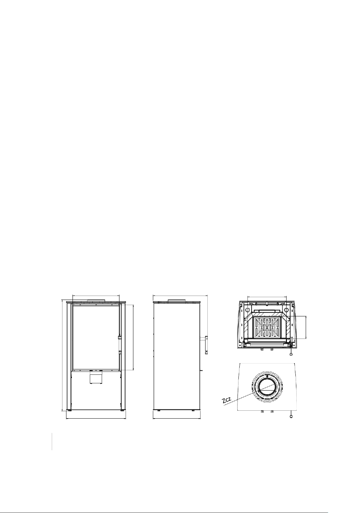
X C E
Fig.
1
LUPO dimensions
B
Y
F
4
Dimensions [mm]
LUPO S
LUPO M
LUPO L
Width
A
502
657
992
Height
B
940
940
940
Overall depth
C
465
465
465
Carcase depth
D
400
400
400
Firebox width
E
326
481
816
Burner depth
F
190
190
190
Air intake diameter
Zd
100
100
100
Flue diameter
Zcz
150
150
150
Glazing width
X
390
545
880
Glazing height
Y
545
545
545
Table
1
LUPO dimensions
E
A
C
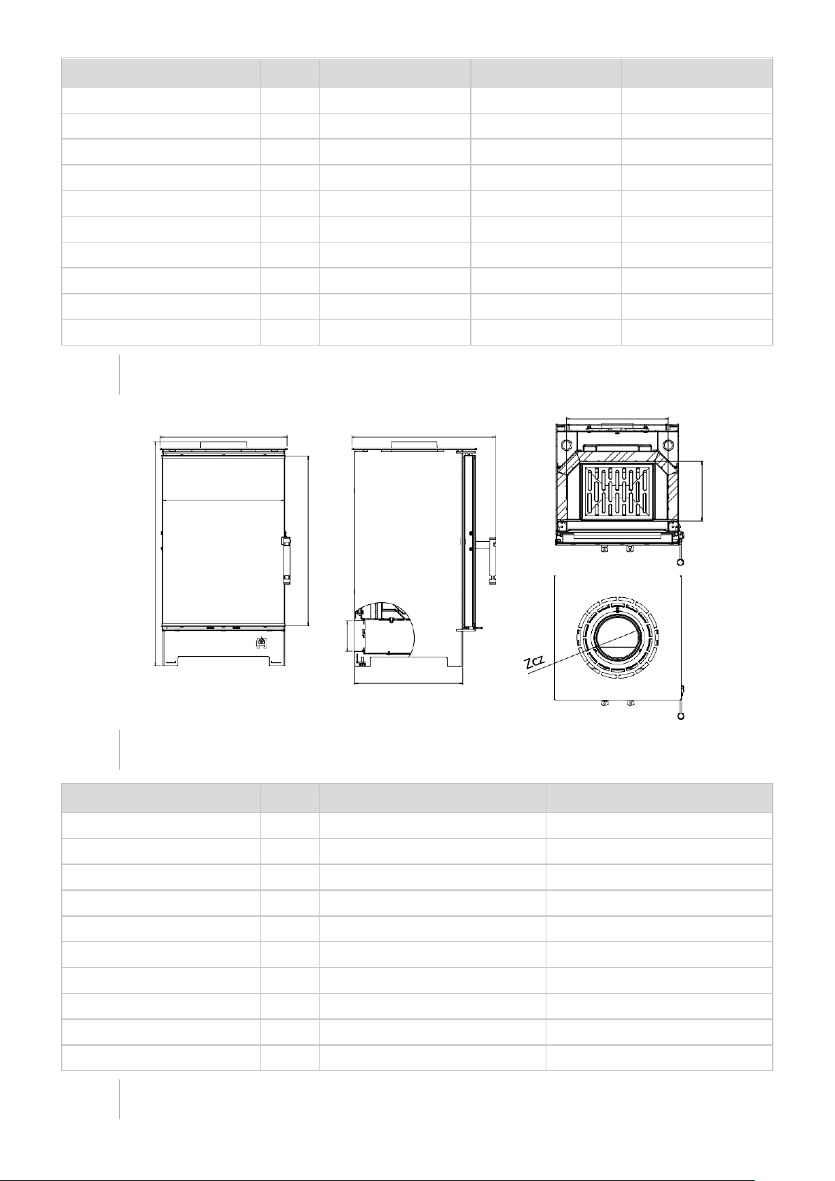
Fig.
2
LYNX cooker dimensions
Dimensions [mm]
LYNX
S
LYNX
B
Width
A
407
453
Height
B
720
760
Overall depth
C
465
506
Carcase depth
D
346
433
Firebox width
E
326
326
Burner depth
F
190
190
Air intake diameter
Zd
100
100
Flue diameter
Zcz
150
150
Glazing width
X
390
365
Glazing height
Y
545
515
Table
2
LYNX cooker dimensions
X
D
B
Y
ZD
F

5
E
A C
Fig.
3
CANE dimensions
Dimensions [mm]
CANE
S
CANE
SF
Width
A
550
550
Height
B
1020
1020
Overall depth
C
465
465
Carcase depth
D
400
360
Firebox width
E
326
326
Burner depth
F
190
190
Air intake diameter
Zd
100
100
Flue diameter
Zcz
150
150
Glazing width
X
390
390
Glazing height
Y
545
545
Table
3
CANE dimensions
D
Zd
X
B
Y
F

6
20
1
2
3
4
16
5
19
6
15
7
14
8
9
13
18
10
11
12
Technical data:
parameter
s
unit
LUPO S,
CANE S, CANE SF
LYNX S, LYNX B
LUPO M
LUPO L
Rated power
kW
6,5
8,8
11
Heating load range
kW
3-8,5
4,5-11,5
5,5-14
Maximum fuel loading weight
kg
1,5
2
2,5
Average fuel consumption
kg/h
1,9
2,6
3,3
Thermal efficiency
%
83,5
83
82
CO emissions (at 13% O2)
g/m3
1,08
1,001
0,921
Pollen emissions (at 13% O2)
g/m3
0,038
0,033
0,028
Average flue gas temperature
˚C
239
235
230
Dimensions of the fireplace glass
mm
390x540
540x540
880x540
Maximum length of billets
mm
350
400
400
Weight
kg
112
140
194
Fuel type
Recommended seasoned hardwoods (beech, birch, hornbeam)
Fuel moisture
between 12 and 20
Table
4
Technical data
1.6.
Construction and operation of cooker

7
1.
flue
2.
deflector
3. flue cap
4.
afterburning system
5.
combustion chamber with
insert
ceramic
6.
cast iron grate
7.
air intake
8.
ashtray
9. special profile doors
10.
back
plate
11.
base plate
12.
adjustment lever
secondary air damper
13.
throttle control lever
primary air
14.
side protection
15. decor glass
16.
handle
17. air curtain
18.
levelling screws
19.
connection of the DGP system
20.
connection of the DGP system
Fig.
4
Construction of the
furnace
Construction:
The cooker is made of boiler steel grade P256GH, 3 mm thick. The inside of the combustion chamber is lined
with a ceramic heat preserving insert
5
. The design allows the flue gases to be led out through the upper or
rear wall of the cooker. The air intake
7
is 100mm in diameter, the flue
1
150mm. The cooker is suitable for
use with a hot air distribution system (DGP)
18,19
. The front of the cooker consists of a steel door
made of
special profile 9 and profiled sheet metal, heat resistant glass 15, and a handle 16, which, thanks to its
special
design, remains cool while burning. The door is bolted to slats fixed to the cooker body.
Activity
description
:
The air enters the cooker through an inlet grille
7
. There are two air inlet systems - primary and secondary.
The amount of incoming primary air is regulated by the right-hand regulation lever on the front of the cooker
under the door
13
. The air then flows around the ash pan
8
and enters the combustion chamber
5 through
the
grate
6
.
The amount of secondary air is regulated by the left lever
12
on the front of the cooker. The air is directed to
the upper part of the combustion chamber
4
to postcombust the flue gases which improves the thermal
efficiency and reduces the amount of pollutant-.
The air volume is adjusted. The air volume is adjusted by pulling the lever to open the air inlet, and pulling it in
to close the air inlet.
The cooker is also equipped with an air curtain 17 to help keep the glass clean. Above the
combustion
chamber
there is a special ceramic plate called deflector
2
, which enhances the heat exchange. During combustion,
the hot gases flow around the deflector and then through the flue
1
and the ducts into the chimney. The
environment around the cooker is heated in two ways - the air surrounding the insert is heated (convection)
and escapes through the ventilation slots in the furnace casing. In addition, heat radiates directly from all hot
parts of the cooker.
2.
TRANSPORT, ASSEMBLY, INSTALLATION COOKER
The device complies with EN 13229:2002 and is CE certified.
Before assembling, installing and operating the cooker, read the following
Operating and
Installation Instructions
carefully
and follow the instructions given therein. This will ensure a
safe and
efficient operation of the cooker. Failure to observe these Operating and Installation
Instructions may invalidate the warranty and endanger the user's life and limb.
National and local regulations and standards must be observed during assembly, installation and operation, in
particular:
▪
Regulation of the Minister of Infrastructure of 12.04.2002. Dz.U.Nr75, poz. 690 with amendments of 07.05.2004.
r. Dz.U.Nr109, pos. 1156;
▪
Standard PN - B - 03406 :1994 Heating. Calculation heat demand;
▪
Standard PN - 89 / B - 10425 Smoke, flue and ventilation ducts made of brick;
▪
Standard PN - 78 / B - 03421.Ventilation and air conditioning. Design parameters of indoor air;
▪
Standard PN-EN 13229:2002 "Fireplace inserts including open fires for solid fuels. Requirements and
tests".
8
It is a requirement that the cooker is installed by a qualified person or company and that technical
acceptance is carried out by a master chimney sweep and a fire specialist.
Sequence of work for cooker installation:
▪
Preparing the location where the cooker is to be installed, checking the load-bearing capacity of the ground
▪
connecting the cooker to the chimney and making an air intake;
▪
using the cooker and observing whether there are any faults or anomalies (approximately 2 weeks).
2.1.
Transport and handling
▪
The cooker is delivered pre-assembled, fixed to a pallet and wrapped in stretch foil;
▪
transportation of the cooker should be done in an upright position;
▪
After unpacking, check the cooker for transport damage;
▪
Unpack the cooker close to the installation site; take care when moving it (preferably with a trolley) (pay
attention to the door and the glass);
▪
cooker packaging materials are not toxic or harmful; they should be recycled or stored by the user;
▪
in order to relieve the load on the cooker, in the event of installation in a difficult location, the ceramic
inserts (which cover the firebox) may be removed; after installation, each element must be correctly put
back in place.
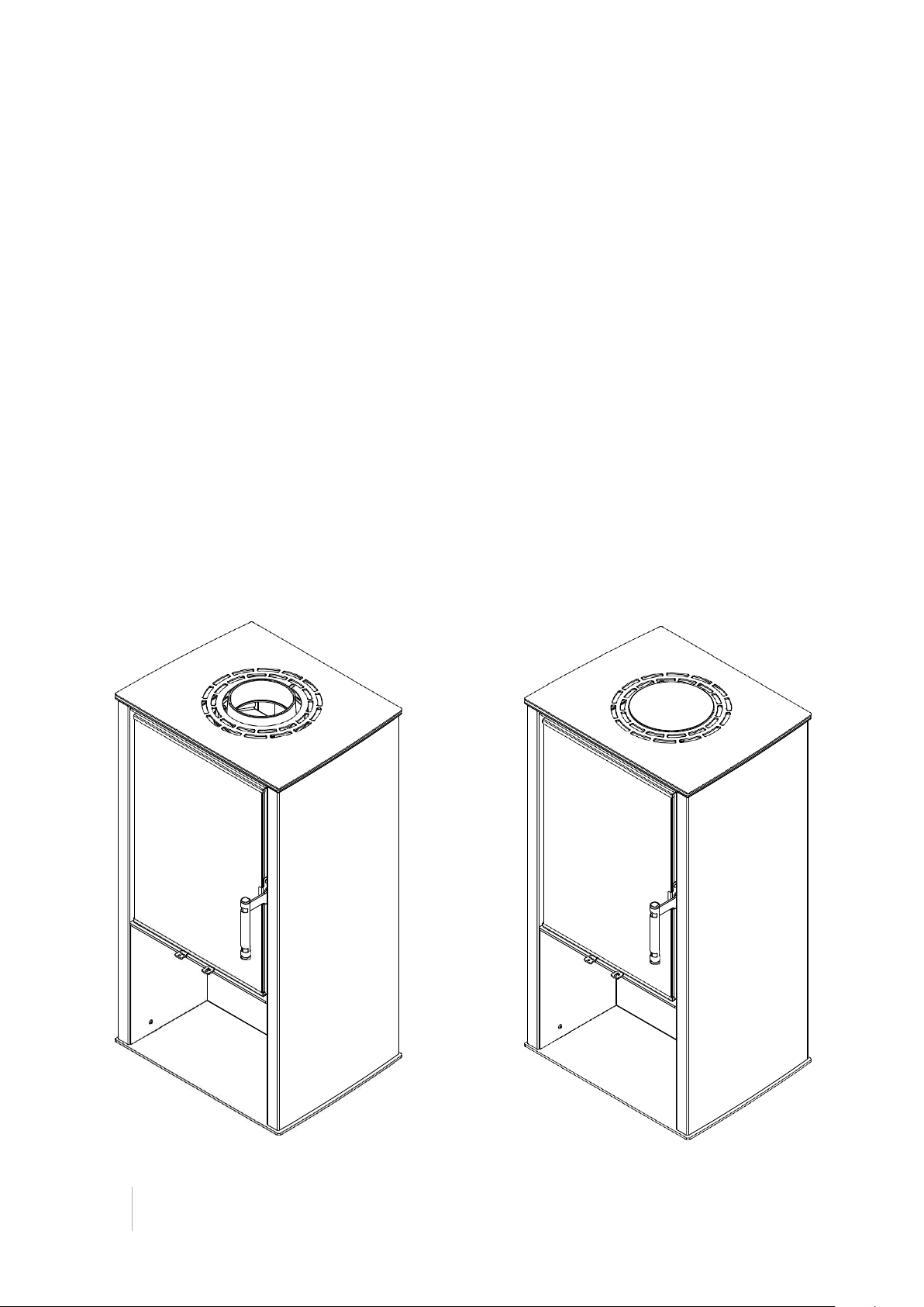
2.2.
Assembly
The design of the cooker allows 2 configurations. The flue can be on the rear wall or the top.
Fig.
5
Cooker
configuration

9
The operation of transferring the flue from the top plate to the rear wall is shown in the
drawing.
1.
view of the cooker in its
factory configuration,
2.
remove the top cover, cut a
hole in the rear panel with a
hacksaw or cut a hole for the
flue with pliers,
3.
Using an allen key, unscrew
the back plate,
4.
using an allen key, unscrew
the flue and cap.
in the rear wall of the cooker,
5.
put
the flue
and the cap in
place and screw them on,
6.
screw the rear panel in place,
put the top cover in place
together with the hob.

10
Fig.
6
Replacement of
flue pipe
11
Fig.
7
Tightening
the feet
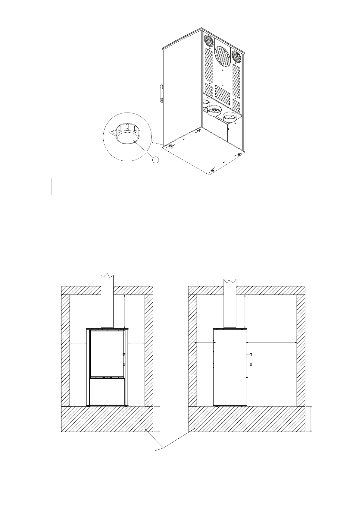
2.3.
Recommendations for substrates:
▪
Before installing the cooker, check the load-bearing capacity of the floor (whether it meets the load-
bearing conditions for the type of appliance depending on its weight);
▪
the floor must be made of a non-combustible material at least 30 cm thick, with a strip of space in front of
the cooker door, at least 60 cm wide and extending beyond the edges of the door by at least 30 cm.
A
A
1
150mm
150mm
150mm
600mm
non-combustible/non-flammable material
400mm
300mm
400mm
300mm
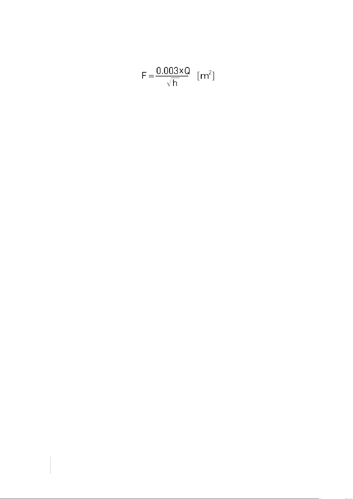
Fig.
8
Recommendations for substrate and
space
10
2.4.
flue
The cooker requires a suitable cross-section of the flue pipe (flue duct) and a suitable height of the flue pipe.
The cross-sectional area of the flue and smoke duct is determined according to the formula:
Where:
F - cross-sectional area of the flue and smoke duct [m2]; Q - rated thermal
output of the insert [kW];
h - chimney height [m].
According to current regulations, the flue must not be smaller than 14x14 cm, or its diameter must be at least
15 cm. Stoves with a higher output require a larger flue pipe cross-section. The cross-section also depends
on the height of the chimney.
The cooker must be connected to a flue pipe or a riser pipe conforming to
current national standards.
The size of the chimney draught should be:
-
minimum draught - 6 ± 2 Pa;
-
AVERAGE, RECOMMENDED DRAINAGE - 12 ± 2 Pa
;
-
maximum draught - 15 ± 2 Pa.
NOTES:
For proper cooker operation it is necessary to ensure a correct draught in the
flue outlet:
▪
Insufficient chimney draught causes poor operation of the cooker, excessive burial of glass and excessive
contamination of the flue gas ducts; the overall heat output of the cooker is reduced (smoke leakage into
the room can occur);
▪
A draught that is too strong can contribute to over-intensive combustion, high fuel consumption and lead
to permanent damage to the cooker.
Regular inspection of the chimney by a chimney sweep is recommended.
2.5.
Connection to the flue:
▪
Before proceeding with the installation of the cooker, an expert's opinion and selection of the flue pipe in
terms of its technical parameters and condition must be carried out;
▪
The installation of the cooker may be carried out following a positive chimney sweep test of the flue pipe.
The flue pipe must comply with the applicable national or European standards.
In accordance with the operating and installation instructions provided, fit and connect the cooker to the
chimney (including installation of screen plates - if used - and insulation of the flue pipe).
The manufacturer does not recommend assembling and installing the appliance yourself. In order to ensure a
proper
and safe start-up of the appliance and the fulfilment of the guarantee conditions, the assembly and
start-up of the appliance must be commissioned by a person or a firm having the appropriate installation
qualifications. The fitter is obliged to confirm in the Warranty Card (entry and stamp) that the installation has
been carried out in compliance with the art. and valid legal regulations. Failure to do so will void the
manufacturer's warranty.
13
1
6
5
4
2
3
1
6
5
4
2
3
2.6.
The flue pipe system should meet the following features:
▪
the cross-section of the flue pipe must not be smaller than that of the flue pipe and must not narrow
towards the chimney (adapters may be used to increase the diameter from the flue pipe to the chimney);
▪
the flue pipe should be as short as possible and have as few bends as possible (increase flow resistance,
avoid condensation build-up);
▪
The cooker must not be connected to a flue pipe which is shared with another heating appliance;
▪
it is advisable to connect the cooker to a separate flue;
▪
the flue pipe may not have more than two inclinations of 45° up to a pipe height of 5m and 20° for pipe
heights of over 5m;
▪
the flue pipe must be made of non-combustible materials and be thermally insulated;
▪
the flue pipe insulation should have a fire resistance of at least 60 minutes;
▪
a straight section of pipe at least twice the diameter of the cooker flue should be used at the exit from the
flue;
▪
the joint should be made tight;
▪
The end of the chimney should allow for a smooth exit of the flue gases and be located at least 60 cm
above the highest point of the roof;
▪
the connectors must be made of stainless steel 1.4401 (316), heat-resistant or fire-resistant steel
adequately painted with a special paint and of an appropriate sheet thickness (heat-resistant and stainless
steel 1 mm thick and fire-resistant 2 mm thick) - the material should be characterised by resistance to
heat, acidity of the flue gas and condensate.
1.
flue pipe,
2. the cleanout,
3.
external air intake,
4.
rosette,
5. sealing mortar,
6.
non-combustible material.
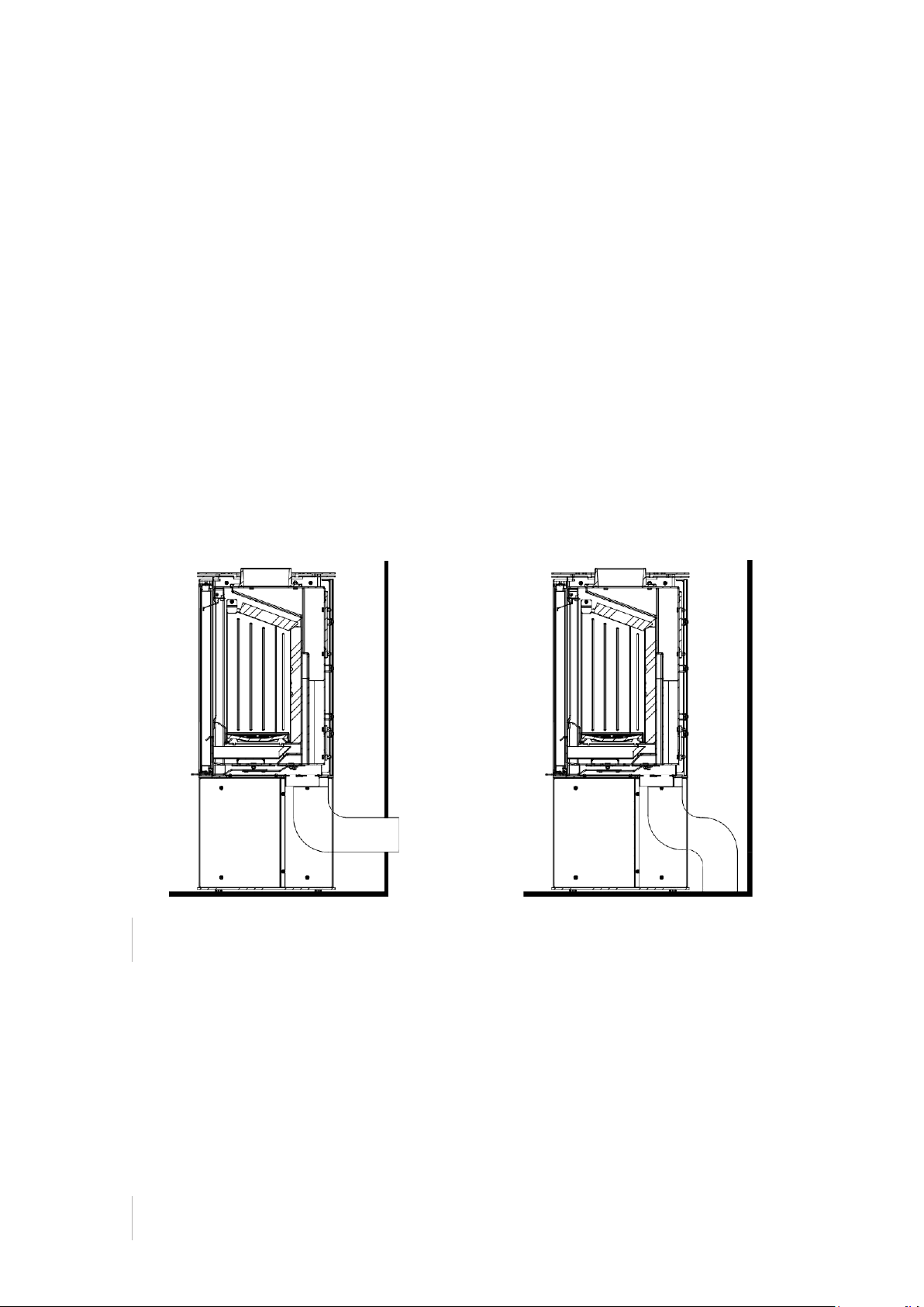
Fig.
9
Diagram of the connection of the cooker to the flue
pipe
12
2.7.
Ventilation cooker:
▪
It is necessary to provide fresh air from outside by unsealing the windows so that there is a
constant supply of air. Too little fresh air from outside can cause poor combustion
(production of carbon monoxide) and, in the worst case scenario, air with carbon monoxide
can backflow through the ventilation ducts when the windows are tightly closed and there is
a risk of fume poisoning;
▪
The design of the cooker allows fresh air to be brought in from the outside (an air pipe with a diameter of
100mm is used). The pipe can be led from the wall behind the back of the cooker or, after turning the
base, from the floor. It is also possible to bring the air in directly from the room where the cooker is
located, provided that there is adequate ventilation to prevent the air supply from closing off automatically.
▪
it is assumed that the amount of air required to burn 1kg of wood is approximately 8 m³;
▪
when using an air distribution system to other rooms, in order to circulate the air freely, ensure that the
cooled air is returned to the room where the cooker is installed (otherwise the operating cycle of the
cooker may be disrupted and the heat distribution process may be impaired);
▪
When determining the location and installation of the unit, attention should be paid to the principles of
correct air circulation and air balance in the room;
▪
Ventilation must be provided in the room where the cooker is installed;
▪
To ensure adequate convection space (cooling of the cooker, heating of the air) the cooker should be
positioned at least 80 cm away from materials which could be distorted or damaged by the heat (furniture,
panelling, wallpaper, etc.).
Fig.
10
Air intake connection diagram
2.8.
Installation
cooker
The unit must be installed in accordance with current building code standards.
Installation and assembly of the cooker must be carried out by qualified professionals.
▪
The cooker must be positioned at a safe distance from any flammable products (it may be necessary to protect
the walls surrounding the cooker);
▪
The space in front of the cooker should be protected to prevent sparks which may fall out of the firebox
when adding fuel. The minimum safe area is 60 cm in front of the cooker and 30 cm to the sides from the
edge of the door. The surface can be protected with natural stone, floor tiles, or a dedicated glass base;


14
▪
Do not install the cooker in bedrooms, bathrooms or rooms where there is another heating appliance
without an independent air supply;
▪
The cooker is a unitary structure and does not require additional supports;
▪
The height (levelling) of the cooker can be adjusted by means of the feet (a maximum of 20 mm can be
unscrewed);
▪
If it is necessary to raise the cooker above the feet adjustment, make a masonry base and place the
appliance on it (do not remove the feet needed for levelling);
▪
If the door is not properly levelled, it will not work properly (it will not close properly);
Fig.
11
Safe area for flammable materials
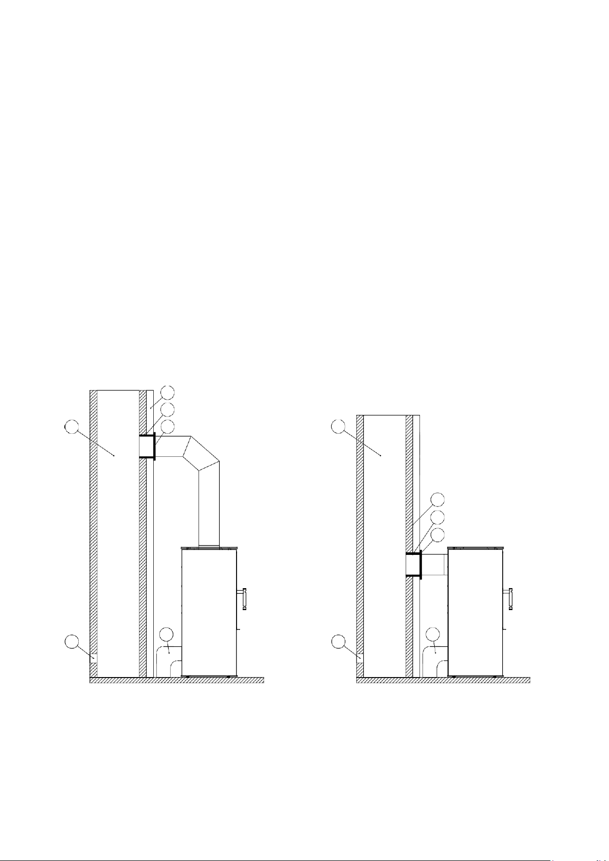
2.9.
Connection of hot air distribution system (DGP)
The hot air distribution system (DGP) allows the convection heat generated by the cooker to be used to heat
other rooms. Different solutions are used depending on the output of the appliance and the installation
conditions. The choice of the right one should be left to a person or company with experience in this field. In
small single-storey houses, a simple gravity system works well. In larger areas, it is sometimes necessary to
use forced-air blowers in the system.
Free-standing cookers allow the DGP system to be connected to the cooker in two ways: from above (LUPO,
CANE, LYNX) or from below (LUPO, CANE). When installing from above, it is necessary to cut out sections of
the rear cover at the locations marked on the drawing. Unobstructed airflow is gained. When assembling the
pipes from below, a blower is required in the system to extract the heated air. The installation of the pipes is
carried out using special fittings with a diameter of 100mm. The cut-outs allow mounting to thin or thick metal
sheets.
Fig.
12
Mounting connection with a diameter of 100 mm
B
B
A - min 1500mm
B - min 150mm
A
B

15
Fig.
13
The arrows indicate the cutting points before fitting the connectors when connecting from above
Fig.
14
Fig.
15
Correctly installed connectors when connected from the top of the cooker
Correctly installed connectors when connected from the bottom of the cooker

16
Pipes carrying the heated air to other rooms are placed on the properly installed connectors. For proper
operation of the system, cool air must be returned to the room where the cooker is located.
3.
STARTING UP
The initial start-up of the cooker, after it has been seated and properly connected to the chimney, must be
carried out by the installer or an authorised service technician. The user must be present during
commissioning so that he/she can be trained by the installer. The installer must refuse to commission the
cooker if he discovers an installation fault which endangers the safety of the user. Correct commissioning
must be confirmed in writing on the guarantee card.
3.1.
Preparation for launch
Before firing up for the first time:
▪
remove any stickers and other paper labels and accessories from the mantle body, ash pan or firebox that
could be the cause of a fire, this also applies to transport protection;
▪
Check that the deflector(s), ceramic pieces and grate are properly seated, and that they have not fallen out of
position during installation (If any seating faults are found, correct them. Otherwise the cooker may not operate
correctly. In cooker types where the door is fitted with a multi-paned glass, check that during transport or use of
the cooker the various parts of the glass have not come apart);
▪
check operation:
•
mechanism for regulating the air supply to the combustion chamber (cold-air dampers);
•
front door locking mechanism (hinges, handle);
3.2.
Firing up the cooker
Before firing up the cooker:
▪
put the thicker logs first in the firebox, then the smaller wood, and finally the small pieces (sub- sticks) -
light with fireplace matches or a lighter;
▪
open the primary air control to maximum and the secondary air control to minimum;
▪
the cooker door must be closed after lighting
;
▪
When the fire is burning well, use the air regulators to adjust the combustion air to a rather damped level
(this means that only a small proportion of the primary air is supplied under the cooker grate; the
secondary air damper is set at max. - the higher amount of air is supplied to the air curtain system, which
protects the glass from scorching and to the post-combustion system at the front of the cooker; opening
the air damper to 100% - as far as possible, results in very intensive combustion of the fire);
▪
it is advisable, in the final stage of combustion, to open the door and burn the remaining embers on the
grate with a poker in order to better burn the fuel;
NOTES:
As a large amount of air is fed under the grate and into the air curtain and
flue gas afterburning
system
, too much fuel in the combustion chamber results in the production of a large amount of
wood
gas
which results in a temporary sooting of the glass.
If the throttle is moved to the right as far as possible, the air supply to the combustion chamber is
completely cut off, resulting in a gradual extinguishing of the firebox.
If necessary, the grate is unclogged with a poker.
During the first hours of operation, it is recommended to operate the cooker at a low load, i.e. up to
50% of the
normal load.
The first ignition may be accompanied by condensation on the inner walls of the combustion
chamber. This phenomenon is normal and results from condensation of the water vapour contained in
the flue gases. It should disappear after the firebox has cooled down.
This manual suits for next models
6
Table of contents
Other HITZE Stove manuals


Popular Stove manuals by other brands

LogFire
LogFire LF6 Installation & operating instructions

PRITY
PRITY PLW11 Technical description and operation instructions

Pacific energy
Pacific energy Classic Gas Installation and operating insctruction manual

redpod
redpod FIRST 6 kW instruction manual

Euroheat
Euroheat EVO Aqua Installation & servicing instructions

Horse Flame
Horse Flame HF-577DU Installation and operation instructions


