www.karles.se
8
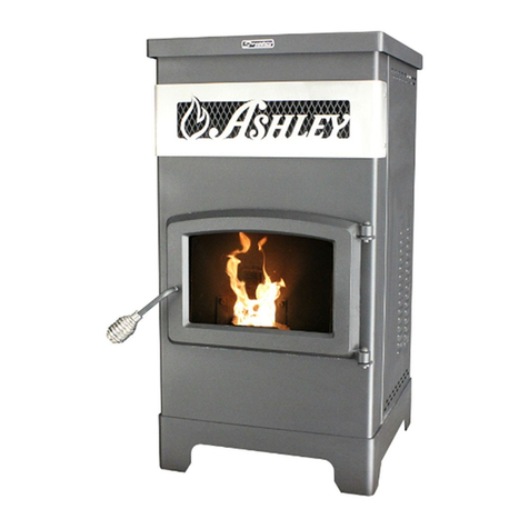
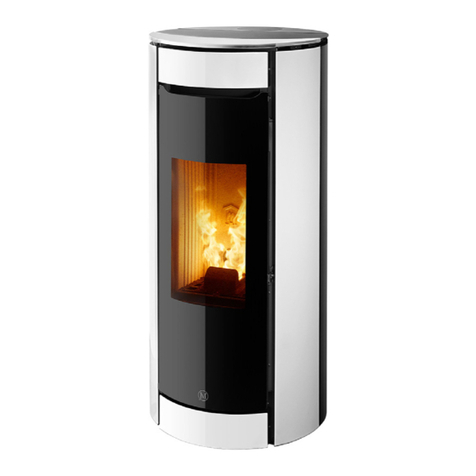
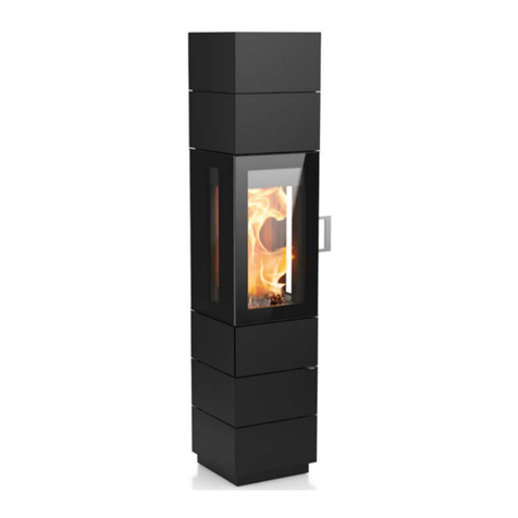
Construction: stove is made of 3mm thick. The combustion chamber 5 is lined with AKUCERAM on
the bottom, side walls and back wall. The design allows the exhaust gas to be led out through the top
or rear wall of the furnace. The air inlet 7 has a diameter of 100mm, flue 1 150mm. The freestanding
stove is adapted to work with a hot air distribution system (DGP) 18,19. The front of the stove consists
of steel door made of special profile 9 and profiled sheet metal, heat resistance glass pane 15, and
handle 16. The door is bolted to the slats attached to the stove body.
A description of the action:
Air enters the furnace throughy the inlet opening 7. There are two air intake system in the
interior – primary and secondary. Adjustment of the amount of incoming primary air takes place via
the right control lever located on the front of the stove under the door 13. Then the air flows around
the ash pan 8 and through the grate 6 it enters the combustion chamber 5.
The amount of secondary air is regulated by the left lever 12 on the front of the stove. The air is
directed to the combustion chamber 4 to burn the exhaust gases, which improves thermal efficiency
and reduces the amount of pollutants. To adjust the amount of air, pull the lever out to open the air
supply and push it in to close the air supply.
The stove Is also equipped with an air curtain 17 to help maintain the clean glass. There is a
special ceramic plate called a deflector above the combustion chamber 2, which enhances heat
exchange. During combustion, hot gases flow around the deflector and then through the flue 1 and
the pipes to the chimney. The stove environment is heated in two ways – the air surrounding the
stove is heated (convection) and escapes through the ventilation slots in the furnace housing. In
addition, the heat radiates directly from all hot parts of the stove.
2. TRANSPORT, , ASSEMBLY AND INSTALLATION OF THE
FREESTANDING STOVE
The device is compliant with the PN-EN 13229:2002 standard and has a CE certificate. Before
assembling, installing and using the stove, read the Operation and Installation Manual carefully
and follow the instructions contained in it. It will ensure safe and efficient operation of the stove.
Non-compliance with this Operation and Installation Manual may invalidate the guarantee and put
the user at risk of injury or loss of life. The product must be assembled, installed and used in
accordance with the national and local laws and standards, including in particular:
• Regulation of the Minister of infrastructure of 12.04.2002 Dz.U.[Polish Journal of Laws] No. 75, item
690 amended on 07.05.2004 Dz.U. [Polish Journal of Laws] No. 109, item 1156;
• PN - B – 03406 Standard:1994 Heating engineering. Calculated heat demand;
• PN – 89 / B – 10425 Standard: Flue pipes, combustions gas ducts and ventilation ducts made
from bricks;
• PN – 78 / B – 03421Standard: Ventilation and air conditioning. Parameters for calculating
indoor air;
• PN-EN 13229:2002 Standard „Inset appliances including open fires fired by solid fuels.
Requirements and test methods”.
The stove must be installed by a qualified person or company and commissioning checks must be
performed by a master chimney sweep and a fire prevention specialist.
The installation of the stove should be performed in the following order:
• preparing the place where the stove is to stand, check the floor’s load-bearing capacity;
• connection of the stove to the chimney and assembly of the air intake ;
• putting the stove into use and observing its functioning for the purpose of detecting


