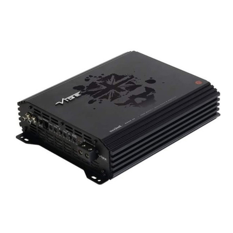
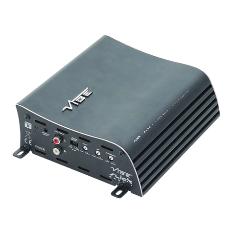
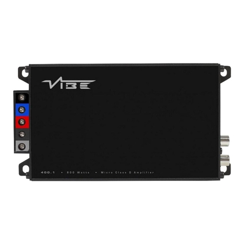
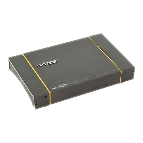
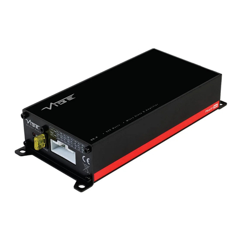
Vibe LITEBOX BASS 1 -V1 User manual

Instore "130"you
canfind and buy almostall necessarygoodsforyourauto
in
Kyiv and othercities,deliveryby ground andpostal services. Ourexperienced
consultantswill provide youwithexhaustive informationand helpyoutochose
the very particular thing.We arewaiting foryou at the address
http://130.com.ua
PHONES
(044) 360-7-130
(050) 336-0-130
(063) 788-0-130
(067) 233-0-130
(068) 282
-
0
-
130
Internet storeof
autogoods
CARRECEIVERS —Receivers •Mediareceiversandstations•Nativereceivers •CD/DVD changers •FM-modulators/USBadapters•Flashmemory•Faciaplates and adapters •Antennas •Accessories |
CARAUDIO —Car audiospeakers •Amplifiers•Subwoofers •Processors•Crossovers •Headphones•Accessories|TRIPCOMPUTERS —Universalcomputers •Modelcomputers •Accessories|
GPSNAVIGATORS —PortableGPS•Built-in GPS•GPSmodules •GPStrackers •Antennas forGPSnavigators•Accessories|VIDEO —DVR •TVsetsand monitors•Car TVtuners•Cameras •Videomodules
•Transcoders •Car TVantennas•Accessories|SECURITYSYSTEMS —Car alarms •Bikealarms •Mechanicalblockers •Immobilizers •Sensors •Accessories |OPTICANDLIGHT —Xenon•Bixenon •Lamps
•LED •Stroboscopes •OpticandHeadlights •Washers •Light,rainsensors •Accessories |PARKTRONICS ANDMIRRORS —Rear parktronics•Frontparktronics •Combined parktronics •Rear-viewmirrors
•Accessories |HEATINGANDCOOLING —Seat heaters •Mirrorsheaters •Screen-wipers heaters •Engineheaters •Auto-refrigerators •Airconditioningunits •Accessories |TUNING —Vibro-isolation
•Noise-isolation •Tintfilms •Accessories |ACCESSORIES —Radar-detectors•Handsfree,Bluetooth•Windowlifters•Compressors •Beeps,loudspeakers •Measuring instruments •Cleaners •Carsits
•Miscellaneous|MOUNTING —Installationkits •Upholstery•Grilles•Tubes•Cableand wire •Tools•Miscellaneous|POWER —Batteries •Converters •Start-chargingequipment•Capacitors
•Accessories |MARINE AUDIOANDELECTRONICS —Marinereceivers•Marineaudiospeakers •Marinesubwoofers •Marineamplifiers•Accessories |CARCARE PRODUCTS —Additives •Washer fluid •
Care accessories •Car polish •Flavors •Adhesives andsealants |LIQUIDANDOIL —Motoroil•Transmissionoil •Brakefluid •Antifreeze•Technicallubricant
ICQ
294-0-130
597-0-130
SKYPE
km-130

Power Amplifier
Instruction Manual
To ensure maximum performance and safety,
please follow this manual. Please retain the
manual for future reference after installation
Models:
LITEBOX BASS 1 -V1
LITEBOX STE E0 2 -V1
LITEBOX STE EO 4 -V1
www.vibeaudio.co.uk
130.com.ua
Autogood products Internet store “130”

Attention
An aftermarket audio amplifier will place an additional load on the vehicles char in system, most modern vehicles have
sufficient capacity in the char in system as not all the electrical components of the vehicle will be switched on at once. Check
the fuse ratin of the amplifier and use this as the peak current requirement, enerally the continuous current draw will be a
third of the peak current, in other words an amplifier fused at 30 amps will have a continuous current draw of 10 amps when
playin music, however it may peak at 30 amps on occasions. Please check with the manufacturer as to whether your vehicle
can cope with the additional load of your amplifier, in some instances it may be necessary to up rade the alternator and battery
or risk dama e to the vehicles electrical system.
Con ratulations on purchasin your VIBE
amplifier, please read this manual in order
to fully understand how to et the best
results from your amplifier and ensure
that all advice on how to look after the
amplifier is followed.
Thank you for buyin VIBE, we hope you
enjoy listenin to your product as much as
we enjoyed creatin it.
VIBE R&D Division
OWNE S MANUAL
This equipment is designed for Supercars, modified and tuned vehicles
and is ideal for marine applications. A specially treated circuit board and
lightweight aluminium construction prevent rust and corrosion. inimal
weight, maximum performance
130.com.ua
Autogood products Internet store “130”

Mounting Guidelines
Your VIBE amplifier is desi ned with a swift installation routine in mind. Please mount the amplifier in a dry location on a solid
surface. NEVER mount the amplifier upside down, this will cause the amplifier to over heat and will eventually dama e the
amplifier. Before fixin the amplifier in place please ensure that there is sufficient air flow around the exterior of the casin ,
at least two inches is sufficient.
Connections
Power Cable
●At least 8 au e cable 8 au e cable should be used for the power connection to the amplifier.
●The power cable should be taken directly from the battery. Rubber rommets should be used when passin throu h
any bulkheads to prevent the cable from becomin chaffed or cut.
●It is vital that a fuse / circuit breaker (of at least equal value to the one fitted on the amplifier) is placed inline with the
power cable and is no further than ei hteen inches away from the battery.
●Please ensure that the fuse is not fitted until the entire installation procedure is complete.
●The two tables below are to help you decide on what cable is correct for you. The first enables you to select the size of
cable dependin on the len th required. The second will help you convert the cable size from American Wire Gau e to
Metric and Imperial if you need to.
Len th of Run
Current demand 0 – 4 Ft 4 – 7 Ft 7 – 10 Ft 10 – 13 Ft 13 – 16 Ft 16 – 19 Ft 19 – 22 Ft 22 – 28 Ft
0–20 amps 14 12 12 10 10 888
20–35 amps 12 10 886 664
35–50 amps 10 88 64 444
50–65 amps 886 44 442
65–85 amps 664 42 220
85–105 amps 664 22 220
105–125 amps 444 20 000
125–150 amps 222 00 000
AWG to Metric and Imperial Conversion Chart
cross sectional area
AWG Number Inch mm mm2
0 0.325 8.25 53.5
1 0.289 7.35 42.4
2 0.258 6.54 33.6
3 0.229 5.83 26.7
4 0.204 5.19 21.1
5 0.182 4.62 16.8
6 0.162 4.11 13.3
7 0.144 3.66 10.5
8 0.128 3.26 8.36
9 0.114 2.91 6.63
10 0.102 2.59 5.26
SPEAKER OUTPUT
8 AWG WIRE TO CHASSIS GROUND
8 AWG WIRE TO REMOTE
(FUSED NEAR BATTERY)
3
130.com.ua
Autogood products Internet store “130”

Ground Cable
●At least 8 au e should be used for the round connection to the amplifier.
●The amplifier round should be connected directly to the chassis of the vehicle, to bare metal.
●The cable len th should be kept to an absolute minimum.
●It is not recommended that you connect the round cable to the vehicles seatbelts anchor point.
emote Turn On
●A minimum of 18 au e cable should be used for this connection.
●The cable should be run with exactly the same care and attention as the power cable and taken back to the source
(headunit) and joined to the remote cable provided.
●If the source (headunit) does not have a remote turn on cable then a 12v supply should be used. This will require a
switch to be fitted inline to enable the amplifier to be turned on and off. Remember that if this switch is left on you will
flatten the car battery.
CA Cables
●Dependin on the model number of your amplifier and the number of speakers you wish to power you will have to run
either one or two RCA cables from the source to the amplifier.
●Please take extra care when runnin these cables from the source to the amplifier. Ensure that they are placed away
from all items that can enerate any interference, wirin harnesses etc.
●It is recommended that the RCA cables should be run on opposite sides of the car to the previously installed power
cables if possible, to avoid the cable pickin up interference.
Auto Sense
●The LiteBox amplifiers feature a Patent pendin auto sense circuit.
●This circuit allows the Litebox amplifier to switch on without a remote turn on wire when connected to the speaker
outputs of a factory headunit .
●The LiteBox auto sense circuit senses the power IC used in most headunits as opposed to sensin si nal, providin
much more consistent operation and also eliminatin annoyin turn on thumps and flat batteries associated with
inferior si nal sensin circuitry.
●When the auto sense circuit is used the remote terminal of the amplifier becomes a switched +12 volt output that can
be used to turn on other components in the audio system such as equalizers, crossovers and other amplifiers without
the auto sense function
Auto Sense Procedure
●Connect the supplied RCA to speaker level to the speaker output of the headunit
●Set the INPUT LEVEL switch to HI
●Set the AUTO SENSE switch to ON
130.com.ua
Autogood products Internet store “130”

Auto sense : controls and connections
Connect the supplied
RCA to speaker level
to the speaker output
of the headunit
Red wire = Positive
Blue wire = Ne ative
+12 VOLT switched output
Set to HI
Set to ON
5
130.com.ua
Autogood products Internet store “130”

1
1112 15
13
2
34
65
98
7
10
16
14
Terminals and controls : LiteBox Bass 1
130.com.ua
Autogood products Internet store “130”

1. Audio input
For connection to the source (headunit) For low level input (this is your RCA output from the source) connect usin RCA leads to the low
level output of the source.
For hi h level input connect the supplied speaker wire to RCA adaptors to the speaker output of the source (see pa e 5 for dia ram)
Left high level input (white RCA plug)
positive - red wire
Ne ative - blue wire
Right high level input (red RCA plug)
Positive - red wire
Ne ative - blue wire
2. Slave input / output
RCA input and output connections used for amplifier strappin
3. High level / low level input select switch
This switch is used to select either hi h level (speaker wire) input or low level (RCA) input
4. Gain control
Used to match the input si nal of the source to the amplifier. See the setup section for more details.
5. Subsonic filter control
This control allows the subsonic filter frequency to be set, the filter is adjustable from 10Hz to 80 Hz
6. Crossover frequency control
This control is used to set the crossover point for the amplifier.
The frequency ran es on the low pass filter are from 30 Hz to 230 Hz,
7. Bass boost frequency control
This control sets the frequency that will be boosted by the bass boost control, the frequency ran es from 30Hz to 125Hz
8. Bass boost control
This control provides up to an extra +15 dB of bass boost at the chosen frequency. Use this boost to increase bass output from the
amplifier.
9. Phase switch
This allows the phase of the amplifier to be set to 0 or 180 de rees, one settin will make the bass from the subwoofer sound more in
time with the front speakers.
10. Source switch
This switch is set accordin to amplifier application, in normal operation it should be set to NORMAL and if the amplifier is actin as a
slave in a strapped confi uration it should be set to SLAVE IN.
11. Gain remote input jack
Use to plu in the remote supplied bass level controller
12. Indicator LED
When the amplifier is operatin correctly the LED will illuminate constant reen
When the amplifier is in protection mode the LED will flash to indicate protection condition - see table for fault code dia nosis.
13. Power connections
See Connections section for details on correct connections.
14. Fuses
Please ensure the followin fuse ratin is used when replacin fuses: 30 amp x 2
15. Speaker terminal output
For connection to the speakers. See Application section for wirin examples.
15. Auto Sense select switch
This switch is used to turn the auto sense circuit on or off (see pa e 5 for more details) 7

130.com.ua
Autogood products Internet store “130”

Set Up Section
To correctly set the ain control of the amplifier to match that of the source (headunit) use the followin setup routine:
Turn the ain control to minimum on the amplifier.
Ensure the bass boost is set to 0 dB.
On the headunit set all crossovers ( if applicable) to flat and both bass and treble to zero.
Turn up the source (headunit) to approx 3/4 volume.
Very slowly turn up the ain on the amplifier until distortion can be heard in any of the speakers or until the volume reaches
an uncomfortable listenin level when this is reached turn down the ain control sli htly.
The gain control is now set.
The settin of the crossover will depend on what kind of speaker you are installin .
For a subwoofer it is recommended that the crossover is set to Low Pass and the frequency is set to match that of the
speakers specifications, or your preferred frequency - this is usally about 60 - 120
.
Note:
By usin the crossovers correctly you will not only len then the life of your speakers but you will also et better performance
from them. To optimise your setup seek the advise of a professional installation en ineer or visit your local VIBE audio dealer.
Amp strapping
The VIBE LiteBox Bass 1 amplifier is capable of being strapped together to deliver the combined output of both amplifiers into a single
channel.
NOTE: only identical amplifiers may be strapped together.
Strapping procedure
· Connect the RCA input from the source unit to the left and right RCA input of the master amplifier.
· Connect a mono RCA lead between the SLAVE OUT output of the master amplifier and the SLAVE IN input
· Set the source switch of the master amplifier to normal
· Set the source switch of the slave amplifier to slave in
· Set the phase switch of the master amplifier to 0 degrees
· Set the phase switch of the slave amplifier to 180 degrees
· Connect speaker cable between the negative speaker output of the master amp and the negative speaker output of the slave
amplifier. The cable must be of the same gauge you will be using to connect the amplifiers to the subwoofer
· The master positive speaker output is to be connected to the subwoofer positive terminal
· The slave positive speaker output is to be connected to the subwoofer negative terminal
130.com.ua
Autogood products Internet store “130”

MASTER AMP SLAVE AMP
MASTER AMP CONTROLS BOTH AMPS
INPUT
SET TO 180
SLAVE AMP CONTROLS DO NOT FUNCTION
CONNECT TO SPEAKER (-) TOGETHER 13 GAUGE MINIMUM
4 OHM MINIMUM
MASTER AMP CONTROLLING MULTIPLE SLAVE AMPS
MASTER AMP CONTROLS ALL AMPS
2 OHM MINIMUM
MASTER AMPCONTROLLING 2 STRAPPED PAIRS
INPUT
SLAVE AMP
SLAVE AMP CONTROLS DO NOT FUNCTION SLAVE AMP CONTROLS DO NOT FUNCTION
SLAVE AMP SLAVE AMP
INPUT
SLAVE AMP SLAVE AMP
MASTER AMP CONTROLS ALL AMPS SLAVE AMPS CONTROLS DO NOT FUNCTION SLAVE AMPS CONTROLS DO NOT FUNCTION
SLAVE AMP
SET TO SLAVE
2 OHM MINIMUM 2 OHM MINIMUM 2 OHM MINIMUM
SET TO 0
SET TO NORMAL
SET TO 0
SET TO SLAVE
SET TO 0
SET TO SLAVE
SET TO 0
SET TO SLAVE
SET TO 0
SET TO NORMAL
SET TO 0
SET TO NORMAL
CONNECT TO SPEAKER (-) TOGETHER 13 GAUGE MINIMUM
4 OHM MINIMUM
CONNECT TO SPEAKER (-) TOGETHER 13 GAUGE MINIMUM
4 OHM MINIMUM
SET TO 180
SET TO SLAVE
SET TO 0
SET TO SLAVE
SET TO 180
SET TO SLAVE
LiteBox Bass 1 applications
Diagram for one VIBE LiteAir Subwoofer
connected to two strapped amplifiers
9
130.com.ua
Autogood products Internet store “130”

Diagram for four VIBE LiteAir Subwoofers connected to
one master and three slave amplifiers
MASTER AMP SLAVE AMP
MASTER AMP CONTROLS BOTH AMPS
INPUT
SET TO 180
SLAVE AMP CONTROLS DO NOT FUNCTION
CONNECT TO SPEAKER (-) TOGETHER 13 GAUGE MINIMUM
4 OHM MINIMUM
MASTER AMP CONTROLLING MULTIPLE SLAVE AMPS
MASTER AMP CONTROLS ALL AMPS
2 OHM MINIMUM
MASTER AMP CONTROLLING 2 STRAPPED PAIRS
INPUT
SLAVE AMP
SLAVE AMP CONTROLS DO NOT FUNCTION SLAVE AMP CONTROLS DO NOT FUNCTION
SLAVE AMP SLAVE AMP
INPUT
SLAVE AMP SLAVE AMP
MASTER AMP CONTROLS ALL AMPS SLAVE AMPS CONTROLS DO NOT FUNCTION SLAVE AMPS CONTROLS DO NOT FUNCTION
SLAVE AMP
SET TO SLAVE
2 OHM MINIMUM 2 OHM MINIMUM 2 OHM MINIMUM
SET TO 0
SET TO NORMAL
SET TO 0
SET TO SLAVE
SET TO 0
SET TO SLAVE
SET TO 0
SET TO SLAVE
SET TO 0
SET TO NORMAL
SET TO 0
SET TO NORMAL
CONNECT TO SPEAKER (-)TOGETHER 13 GAUGE MINIMUM
4 OHM MINIMUM
CONNECT TO SPEAKER (-)TOGETHER 13 GAUGE MINIMUM
4 OHM MINIMUM
SET TO 180
SET TO SLAVE
SET TO 0
SET TO SLAVE
SET TO 180
SET TO SLAVE
130.com.ua
Autogood products Internet store “130”

Diagram for two VIBE LiteAir Subwoofers
connected to one master and three slave
amplifiers configured as two strapped pairs
MASTER AMP SLAVE AMP
MASTER AMP CONTROLS BOTH AMPS
INPUT
SET TO 180
SLAVE AMP CONTROLS DO NOT FUNCTION
CONNECT TO SPEAKER (-) TOGETHER 13 GAUGE MINIMUM
4 OHM MINIMUM
MASTER AMP CONTROLLING MULTIPLE SLAVE AMPS
MASTER AMP CONTROLS ALL AMPS
2 OHM MINIMUM
MASTER AMP CONTROLLING 2 STRAPPED PAIRS
INPUT
SLAVE AMP
SLAVE AMP CONTROLS DO NOT FUNCTION SLAVE AMP CONTROLS DO NOT FUNCTION
SLAVE AMP SLAVE AMP
INPUT
SLAVE AMP SLAVE AMP
MASTER AMP CONTROLS ALL AMPS SLAVE AMPS CONTROLS DO NOT FUNCTION SLAVE AMPS CONTROLS DO NOT FUNCTION
SLAVE AMP
SET TO SLAVE
2 OHM MINIMUM 2 OHM MINIMUM 2 OHM MINIMUM
SET TO 0
SET TO NORMAL
SET TO 0
SET TO SLAVE
SET TO 0
SET TO SLAVE
SET TO 0
SET TO SLAVE
SET TO 0
SET TO NORMAL
SET TO 0
SET TO NORMAL
CONNECT TO SPEAKER (-)TOGETHER 13 GAUGE MINIMUM
4 OHM MINIMUM
CONNECT TO SPEAKER (-)TOGETHER 13 GAUGE MINIMUM
4 OHM MINIMUM
SET TO 180
SET TO SLAVE
SET TO 0
SET TO SLAVE
SET TO 180
SET TO SLAVE
11
130.com.ua
Autogood products Internet store “130”

Terminals and controls : LiteBox Stereo 2
23 4
11
2369
1
1112 15
13
2
34
6 5
98
7
10
16
14
1
710
1
1
13
10
5
6
8 9
4 5 7 8
11
12
14
130.com.ua
Autogood products Internet store “130”

1. Audio input
For connection to the source (headunit) For low level input (this is your RCA output from the source) connect usin RCA leads to the low
level output of the source.
For hi h level input connect the supplied speaker wire to RCA adaptors to the speaker output of the source (see pa e 5 for dia ram)
Left high level input (white RCA plug)
positive - red wire
Ne ative - blue wire
Right high level input (red RCA plug)
Positive - red wire
Ne ative - blue wire
2. High level / low level input select switch
This switch is used to select either hi h level (speaker wire) input or low level (RCA) input
3. Gain control
Used to match the input si nal of the source to the amplifier. See the setup section for more details.
4. Crossover mode switch
The switch is used to select between low pass filter LP, hi h pass filter HP or no filter at all OFF.
5. Crossover frequency control
This control is used to set the crossover point for the amplifier. The frequency ran es on the low pass filter are from 55 Hz to 550 Hz,
The frequency ran es on the hi h pass filter are from 55 Hz to 550Hz.
6. Bass boost control
This control provides up to an extra +15 dB of bass boost at 45 Hz. Use this boost to increase bass output from the amplifier.
7. Indicator LED
When the amplifier is operatin correctly the LED will show as blue.
When the amplifier is in protection mode the LED will flash to indicate protection mode.
8. Power connections
See Connections section for details on correct installation.
9. Fuses
Please ensure the followin fuse ratin is used when replacin fuses: 30 amp x 1
10.Speaker terminal output
For connection to the speakers. See Application section for wirin examples.
11. Auto Sense select switch
This switch is used to turn the auto sense circuit on or off (see pa e 5 for more details)
13
130.com.ua
Autogood products Internet store “130”

LiteBox Stereo 2 applications
Diagram for a LiteBox stereo 2 connected to a single LiteAir 12 wired
for 4 ohms
Diagram for a LiteBox Stereo 2 running a pair of LiteAir 5 component
speakers
4 Ohm Minimum
2 Ohm Minimum
130.com.ua
Autogood products Internet store “130”

Set Up Section
To correctly set the ain control of the amplifier to match that of the source (headunit) use the followin setup routine:
Turn the ain control to minimum on the amplifier.
Ensure the bass boost is set to 0 dB.
On the headunit set all crossovers ( if applicable) to flat and both bass and treble to zero.
Turn up the source (headunit) to approx 3/4 volume.
Very slowly turn up the ain on the amplifier until distortion can be heard in any of the speakers or until the volume reaches
an uncomfortable listenin level when this is reached turn down the ain control sli htly.
The gain control is now set.
The settin of the crossover will depend on what kind of speaker you are installin .
For a subwoofer it is recommended that the crossover is set to Low pass and the frequency is set to match that of the
speakers specifications, or your preferred frequency - this is usually about 60 - 120 Hz
For a pair of full ran e speakers it is recommended that the crossover is set to Flat. The two frequency controls will then
have no effect on the amplifiers output and the speaker will receive a full ran e si nal. However, usin the hi h pass
crossovers will allow more control of your speakers. By removin the bass (low frequencies) the speakers can perform at
hi her volumes with less distortion.
Note: The smaller the speaker, the less bass it can handle. Adjust the crossover to et the most and best sound from your
speakers. The easiest was to do this is by limitin the amount of bass you feed them.
For a pair of speakers with a passive crossover it is recommended that the crossover is set to Hi h Pass and the frequency
is set to match that of the speakers specifications. - This is usually about 40 - 120Hz
Note:
By usin the crossovers correctly you will not only len then the life of your speakers but you will also et better performance
from them. To optimise your setup seek the advise of a professional installation en ineer or visit your local VIBE audio dealer.
15
130.com.ua
Autogood products Internet store “130”

Terminals and controls : LiteBox Stereo 4
234
11
23 6 9
1
1112 15
13
2
34
6 5
98
7
10
16
14
1
710
1
1
13
10
5
6
89
4578
11
12
14
130.com.ua
Autogood products Internet store “130”

1. Audio input
For connection to the source (headunit) For low level input (this is your RCA output from the source) connect usin RCA leads to the low
level output of the source.
For hi h level input connect the supplied speaker wire to RCA adaptors to the speaker output of the source (see pa e 5 for dia ram)
Left high level input (white RCA plug)
positive - red wire
Ne ative - blue wire
Right high level input (red RCA plug)
Positive - red wire
Ne ative - blue wire
2. High level / low level input select switch
This switch is used to select either hi h level (speaker wire) input or low level (RCA) input
3. Front gain control
Used to match the input si nal of the source to the amplifier. See the setup section for more details.
4. Front crossover mode switch
The switch is used to select between low pass filter LP, hi h pass filter HP or no filter at all OFF.
5. Front crossover frequency control
This control is used to set the crossover point for the amplifier. The frequency ran es on the low pass filter are from 55 Hz to 550 Hz,
The frequency ran es on the hi h pass filter are from 55 Hz to 5.5 KHz.
6. ear gain control
Used to match the input si nal of the source (headunit). to the amplifier. See the setup section for more details.
7. ear crossover mode switch
The switch is used to select between low pass filter LP, hi h pass filter HP or no filter at all OFF.
8. ear crossover frequency control
This control is used to set the crossover point for the amplifier.
The frequency ran es on the low pass filter are from 55 Hz to 550 Hz, The frequency ran es on the hi h pass filter are from 55 Hz to
5.5 KHz.
9. Bass boost control
This control provides up to an extra +15 dB of bass boost at 45 Hz. Use this boost to increase bass output from the amplifier.
10. Indicator LED
When the amplifier is operatin correctly the LED will show as blue.
When the amplifier is in protection mode the LED will flash to indicate protection mode.
11. Power connections
See Connections section for details on correct installation.
12. Fuses
Please ensure the followin fuse ratin is used when replacin fuses: 30 amp x 2
13.Speaker terminal output
For connection to the speakers. See Application section for wirin examples.
11. Auto Sense select switch
This switch is used to turn the auto sense circuit on or off (see pa e 5 for more details)
17
130.com.ua
Autogood products Internet store “130”

LiteBox Stereo 4 applications
Diagram for a LiteBox Stereo 4 running three channel connected to a pair
of LiteAir 5 component speakers and a single LiteAir 12 wired for 4 ohms
Diagram for a SpaceBox Stereo 4 running for channel connected to two
pairs of Space 5 component speakers
2 Ohm Minimum
4 Ohm Minimum
2 Ohm Minimum
2 Ohm Minimum
130.com.ua
Autogood products Internet store “130”

Set Up Section
To correctly set the ain control of the amplifier to match that of the source (headunit) use the followin setup routine:
Turn the ain control to minimum on the amplifier.
Ensure the bass boost is set to 0 dB.
On the headunit set all crossovers ( if applicable) to flat and both bass and treble to zero.
Turn up the source (headunit) to approx 3/4 volume.
Very slowly turn up the ain on the amplifier until distortion can be heard in any of the speakers or until the volume reaches
an uncomfortable listenin level when this is reached turn down the ain control sli htly.
The gain control is now set.
The settin of the crossover will depend on what kind of speaker you are installin .
For a subwoofer it is recommended that the crossover is set to Low pass and the frequency is set to match that of the
speakers specifications, or your preferred frequency - this is usually about 60 - 120 Hz
For a pair of full ran e speakers it is recommended that the crossover is set to Flat. The two frequency controls will then
have no effect on the amplifiers output and the speaker will receive a full ran e si nal. However, usin the hi h pass
crossovers will allow more control of your speakers. By removin the bass (low frequencies) the speakers can perform at
hi her volumes with less distortion.
Note: The smaller the speaker, the less bass it can handle. Adjust the crossover to et the most and best sound from your
speakers. The easiest was to do this is by limitin the amount of bass you feed them.
For a pair of speakers with a passive crossover it is recommended that the crossover is set to Hi h Pass and the frequency
is set to match that of the speakers specifications. - This is usually about 40 - 120Hz
Note:
By usin the crossovers correctly you will not only len then the life of your speakers but you will also et better performance
from them. To optimise your setup seek the advise of a professional installation en ineer or visit your local VIBE audio dealer.
19
Specification Bass 1 Stereo 2 Stereo 4
RMS Power @ 13.8v DC
Power @ 4 Ohms stereo n/a 2 x 90 watts R S 4 x 90 watts R S
Power @ 2 Ohms stereo n/a 2 x 125 watts R S 4 x 125 watts R S
Power @ 4 Ohms mono 300 watts R S 1 x 250 watts R S 2 x 250 watts R S
Power @ 2 Ohms mono 500 watts R S n/a n/a
ax power 1000 watts 500 watts 1000 watts
Strapped power @ 8 Ohms mono 600 watts R S n/a n/a
Strapped power @ 4 Ohms mono 1000 watts R S n/a n/a
inimum speaker impendence 2 Ohms 2 Ohms stereo 2 Ohms stereo
4 Ohms mono 4 Ohms mono
THD Distortion 0.01% 0.01% 0.01%
I D Distortion 0.01% 0.01% 0.01%
Frequency Response 20Hz - 230 Hz 1Hz - 69 Khz 1Hz - 69 Khz
Input Sensitivity 0.3V - 7V 0.3V - 7V 0.3V - 7V
Input Impendence 10 K ohms 47.5K ohms 47.5K ohms
Signal to Noise Ratio 82dB 111 dB 109 dB
Channel Separation N/A 61 dB 74 dB
Remote GAIN control 0.3mV - 7V N/A N/A
Crossover Network
Low pass filter 30 Hz – 230 Hz 55 Hz – 550 Hz 55 Hz – 550 Hz
High pass filter n/a 55 Hz – 550 Hz 55 Hz – 550 Hz
Bass boost 0 dB - +15 dB 0 dB - +15 dB 0 dB - +15 dB
Subsonic filter 10 Hz – 80 Hz N/A N/A
Fuse rating 30A x 2 30A x 1 30A x 2
Size height x width x depth 50 x 295 x 135 (mm) 50 x 210 x 135 (mm) 50 x 295 x 135 (mm)
130.com.ua
Autogood products Internet store “130”
This manual suits for next models
2
Table of contents
Other Vibe Amplifier manuals

Vibe
Vibe Slick Stereo 2 User manual

Vibe
Vibe Monobox III User manual

Vibe
Vibe STEREO 2 User manual

Vibe
Vibe SPACEBS4 -V1 User manual

Vibe
Vibe Powerbox Micro POWERBOX 400.1M User manual

Vibe
Vibe 7 Series User manual

Vibe
Vibe Slick a7 User manual

Vibe
Vibe POWERBOX 60.5 User manual

Vibe
Vibe BASS4-V1 User manual

Vibe
Vibe Slick a2 User manual