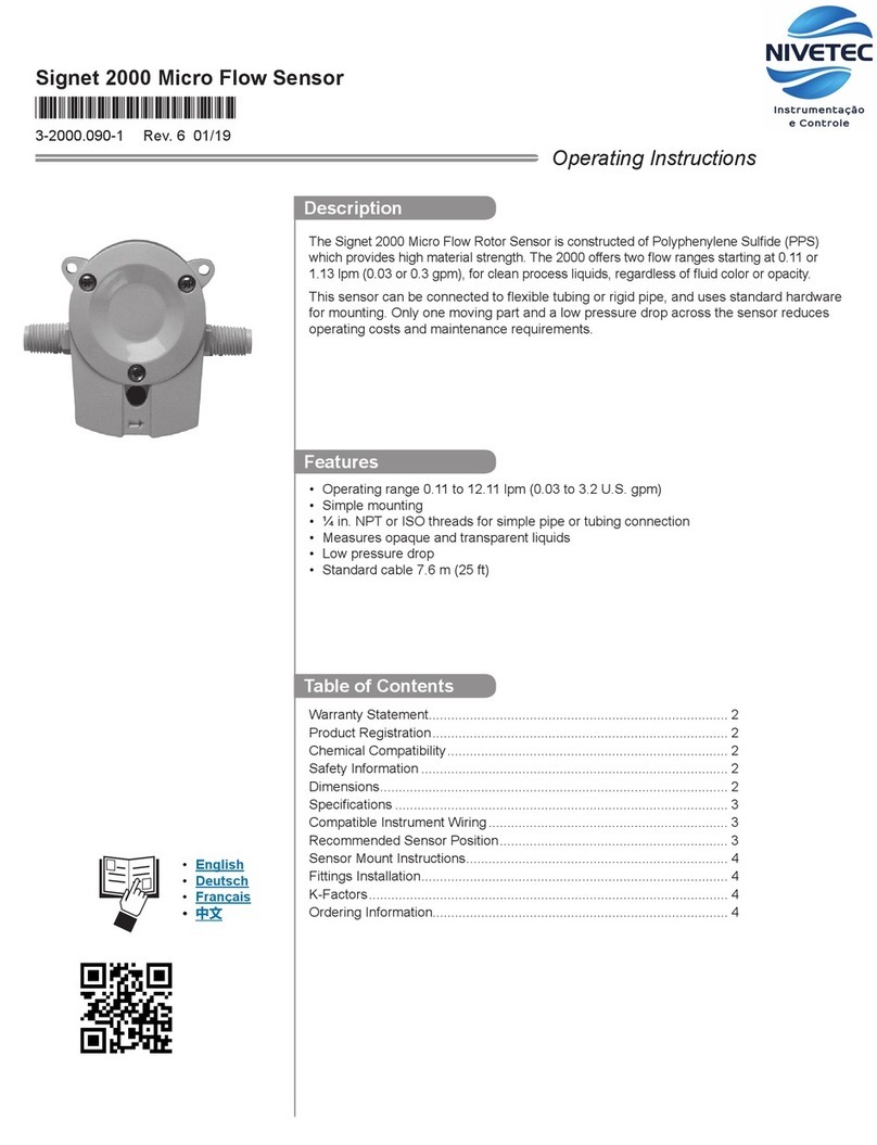
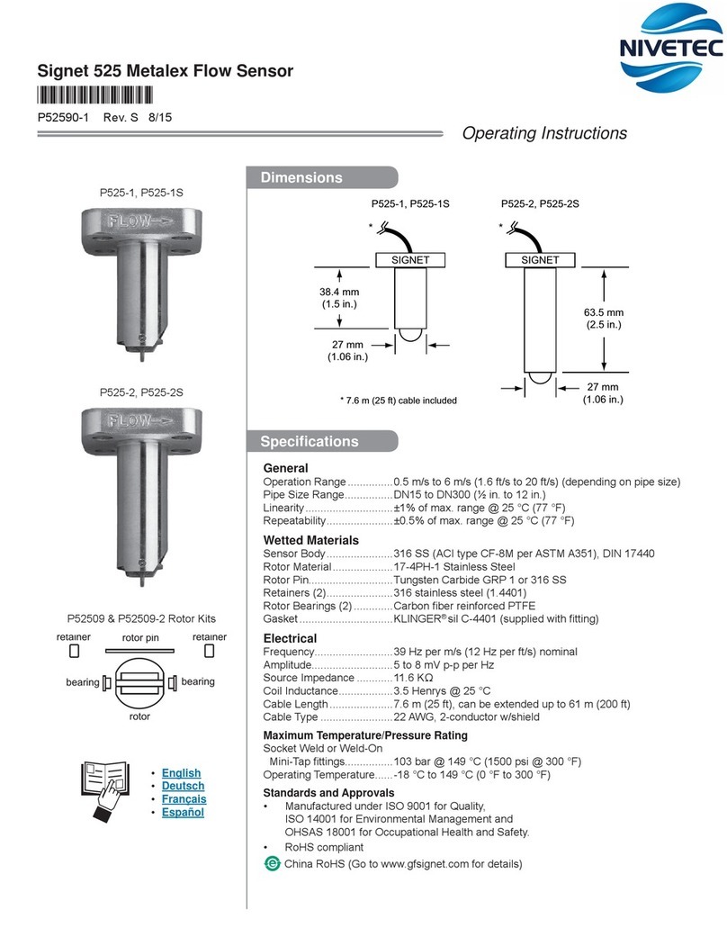
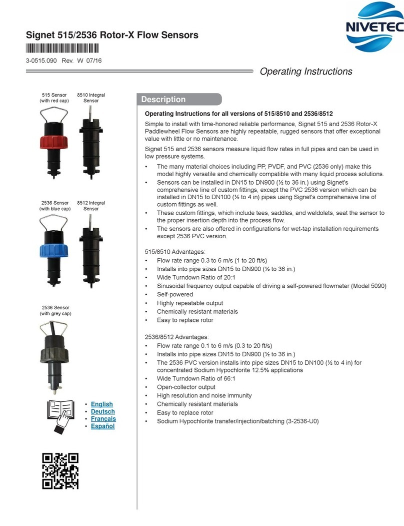
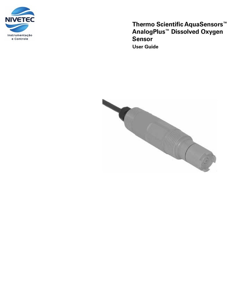
Nivetec Thermo Scientific AquaSensors AquaClear AQT... User manual

Thermo Scientific AquaSensors™
AquaClear™Low Range
Turbidimeter
User Guide

ROSS and the COIL trade dress are trademarks of Thermo Fisher Scientific Inc. U.S. patent 6,793,787.
AQUAfast, Cahn, ionplus, KNIpHE, No Cal, ORION, perpHect, PerpHecT, PerpHecTion, pHISA, pHuture, Pure Water, Sage, Sensing the Future, SensorLink,
ROSS, ROSS Ultra, Sure-Flow, Titrator PLUS and TURBO2 are registered trademarks of Thermo Fisher.
1-888-pHAX-ION, A+, All in One, Aplus, AQUAsnap, AssuredAccuracy, AUTO-BAR, AUTO-CAL, AUTO DISPENSER, Auto-ID, AUTO-LOG, AUTO-READ,
AUTO-STIR, Auto-Test, BOD AutoEZ, Cable-Free, CERTI-CAL, CISA, DataCOLLECT, DataPLUS, digital LogR, DirectCal, DuraProbe, Environmental Product
Authority, Extra Easy/Extra Value, FAST QC, GAP, GLPcal, GLPcheck, GLPdoc, ISEasy, KAP, LabConnect, LogR, Low Maintenance Triode, Minimum Stir
Requirement, MSR, NISS, One-Touch, One-Touch Calibration, One-Touch Measurement, Optimum Results, Orion Star, Pentrode, pHuture MMS, pHuture
Pentrode, pHuture Quatrode, pHuture Triode, Quatrode, QuiKcheK, rf link, ROSS Resolution, SAOB, SMART AVERAGING, Smart CheK, SMART STABILITY,
Stacked, Star Navigator 21, Stat Face, The Enhanced Lab, ThermaSense, Triode, TRIUMpH, Unbreakable pH, Universal Access are trademarks of
Thermo Fisher.
Guaranteed Success and The Technical Edge are service marks of Thermo Fisher.
PerpHecT meters are protected by U.S. patent 6,168,707.
PerpHecT ROSS electrodes are protected by U.S. patent 6,168,707.
ORION Series A meters and 900A printer are protected by U.S. patents 5,198,093, D334,208 and D346,753.
ionplus electrodes and Optimum Results solutions are protected by U.S. patent 5,830,338.
ROSS Ultra electrodes are protected by U.S. patent 6,793,787.
ORP standard is protected by U.S. patent 6,350,367.
No Cal electrodes are protected by U.S. patent 7,276,142.
© 2009 Thermo Fisher Scientific Inc. All rights reserved. All trademarks are the property of Thermo Fisher Scientific Inc. and its subsidiaries.
The specifications, descriptions, drawings, ordering information and part numbers within this document are subject to change without notice.
This publication supersedes all previous publications on this subject.

Thermo Scientific AquaSensors™AquaClear™Low Range Turbidimeter User Guide 1
Preface
This instruction manual serves to explain the use of the Thermo Scientific AquaSensors AquaClear Turbidity
System and is written to cover as many applications as possible. Please do nothesitate to contactThermo
Fisher Scientific or an authorized representative with questions or concerns.
The information presented in this instruction manual is subject to change withoutnotice as improvements are
made, and does notrepresent any commitment whatsoever on the partof Thermo Fisher Scientific.
Thermo Fisher Scientific cannotacceptany responsibility for damage or malfunction ofthe equipment due to
improper use.
Contact Information
To contactThermo Scientific AquaSensors Technical Support:
Within the United States call 1.800.225.1480 or fax 978-232-6015.
Outside the United States call 978.232.6000 or fax 978.232.6031.
In Europe, the Middle East and Africa,contact your localauthorized dealer.
Visitus on the web at www.thermo.com/processwater

Thermo Scientific AquaSensors™AquaClear™Low Range Turbidimeter User Guide 2
Safety Information
The AquaClear Turbidity System shall be installed and operated only
in the manner specified. Only a skilled, trained or authorized person
should carry out installation, setup and operation of the sensor
system.
Before using the system, make sure that is connected as specified.
Failure to do so may result in permanent damage to the system of its
components.
Protection against electric shock will be achieved only by observance
of the corresponding installation rules.

Thermo Scientific AquaSensors™AquaClear™Low Range Turbidimeter User Guide 3
TABLE OF CONTENTS
1. INTRODUCTION..........................................................................................................................4
1.1. GENERAL INFORMATION................................................................................................................4
1.2. INTENDED USE...............................................................................................................................5
2. PRODUCT DESCRIPTION..........................................................................................................6
3. MOUNTING, WIRING AND PLUMBING..................................................................................7
3.1. MOUNTING ...................................................................................................................................7
3.2. PLUMBING ....................................................................................................................................8
3.3. WIRING AND 24 VDC POWER........................................................................................................9
3.4. SAMPLE CHAMBER DETAILS........................................................................................................ 11
4. MEASURE SCREEN OVERVIEW............................................................................................ 12
5. MENU STRUCTURE..................................................................................................................13
6. CALIBRATION...........................................................................................................................17
6.1. SPAN CALIBRATION..................................................................................................................... 17
6.2. ZERO CALIBRATION .................................................................................................................... 20
6.3. TEMPERATURE CALIBRATION ......................................................................................................22
7. CONFIGURATION..................................................................................................................... 25
8. DATASTICK COMMS MENU...................................................................................................27
8.1. SETTING DATASTICK STATION NUMBER ......................................................................................27
8.2. SETTING DATA TYPE ................................................................................................................... 28
8.3. SETTING DATASTICK BAUD RATE ............................................................................................... 29
8.4. SETTING DATASTICK PARITY ...................................................................................................... 29
9. ANALOG OUTPUT(S)................................................................................................................ 30
10. RELAY (OPTION) ......................................................................................................................34
11. HELP MENU ...............................................................................................................................35
12. RESET AV38................................................................................................................................36
13. PERFORMANCE SPECIFICATION.........................................................................................37
14. TURBIDITY SYSTEM ORDER MATRIX AND ACCESSORIES...........................................39
15. LIMITED WARRANTY ............................................................................................................. 41
16. TERMS AND CONDITIONS...................................................................................................... 42

Thermo Scientific AquaSensors™AquaClear™Low Range Turbidimeter User Guide 4
1. INTRODUCTION
1.1. General Information
Thank you for purchasing the AquaClear Drinking Water Turbidimeter.
The product is designedfor continuous use in industrialprocess applications and complies with safety
regulations currently in force. Improper use could lead to hazards for the user or a third-party, and/or adverse
effects to the plant or other equipment.
Thermo Fisher Scientific does not accept any liability for damage that may arise if information in this
manual is not followed. Therefore, the operating instructions and specifications must be read and
understood by all persons involved in installation and operation of this equipment.
This manualidentifies safety instructions and additional information by means of the followingsymbols:
This symbol draws attention to safety instructions and warnings of potential danger,
which if neglected,could result in injury to persons and/or damage to property.
This symbol identifies additional information and instructions, which if neglected, could
lead to inefficient operation and possible loss of production.
Itis recommended that this manual be made accessibleto everyone who may need it as a reference.
Please contactThermo Fisher Scientific or an authorized representative with any questions.

Thermo Scientific AquaSensors™AquaClear™Low Range Turbidimeter User Guide 5
1.2. Intended use
The AquaClear Turbidity Systemis used for continuous monitoring of low-range turbidity in drinking water
applications. The systemalso measures water temperature.
Data is reported through a local display and a scalable 4-20 milliamp current output. Options include a
second current output, up to 2 configurable relays and one ofseveral digital protocols for remote monitoring,
calibration, configuration and diagnostics.
Any other use,or use not mentioned here, that is incompatible with the technical specifications is deemed
inappropriate. The operator is solely responsible for any damage arising from such use.
Other prerequisites for appropriate use include:
•Observing the instructions,notes and requirements setout in this instruction manual.
•Observing all local safety regulations.
•Observing all warnings and cautions in the documentation regarding all products used in this
measurementsystem, including the sensor,mounting hardware, AV38 electronics and cabling.
•Observing the prescribed environmental and operationalconditions.
•Observing chemical compatibility with all wetted materials.
1.3. Safety Instructions
The Turbidity System should be installed and operated only by personnel familiar with
the sensor and qualified for such work.
A defective Turbidity System should be returned to Thermo Fisher Scientific for repair
or replacement. Contact Thermo Fisher Scientific to obtain a Return Material
Authorization (RMA) number.
No modifications to the Turbidity System are allowed. The manufacturer/supplier
accepts no responsibility for damage caused by unauthorized modifications. The risk
is borne entirely by theuser.
1.4. Removalfrom Service / Correct Disposalof the Turbidity System
Removal from Service
•Disconnect the cable wiring from the controller terminalblock.
•Remove the Turbidity Systemfrom the mounting hardware.
Correct Disposalof Unit
•When the Turbidity Systemis taken out of service, observe the local environmentalregulations for
correctdisposal.

Thermo Scientific AquaSensors™AquaClear™Low Range Turbidimeter User Guide 6
2. PRODUCT DESCRIPTION
The AquaClear Turbidity Systemis used for continuous monitoring of low-range turbidity in drinking water
applications. The systemalso measures water temperature.
In the standard system configuration,data is reported through a local display and a scalable 4-20 milliamp
currentoutput. Options include a second current output,up to 2 configurable relays and one of severaldigital
protocols for remote monitoring, calibration,configuration and diagnostics. All functions can be accessed
through a digitalnetwork with or without a localdisplay interface.
The AquaClear Turbidity System uses a pre-calibrated optical detector mounted in a sample chamber
specifically designed to prepare water for low-range turbidity measurements. A collimated white light in the
chamber lid is used to illuminate particles suspended in the water.
The chamber removes bubbles from the water so that solid particles can be accurately detected. The
chamber lamp will provide collimated white light for up to two years and is easily changed from the top.
Because the chamber volume is only 135 milliliters, it takes a very small amount of Formazin to perform EPA
mandated calibrations.
Highlights:
Meets USEPA Method 180.1
Pre-calibrated Measurement
Plug and Play Optical Detector
135 ml Sample Chamber
0.001 NTU Resolution
FastResponse
2 year light source
Compact mounting footprint
Digital Networking Interface
Local Interface with currentloops and relays
Low flow rate
Temperature measurementincluded
Plugand Play IndustrialCommunications Adapters
The AquaClear Drinking Water Turbidity systemis part of the DataStick family of products. The DataStick can
be used with any sensor head manufactured by Thermo Fisher Scientific and can communicate directly with
industrial computer systems using any of the communications adapters offered. The Thermo Scientific
AquaSensors AV38 local display is provided as standard equipment for the Turbidity System. It is however
not required and any number of turbidity systems can be digitally networked to a single computer interface.
Open protocol commands for calibration, configuration, diagnostics and measurement are available (consult
the desired communications manual).

Thermo Scientific AquaSensors™AquaClear™Low Range Turbidimeter User Guide 7
3. Mounting, Wiring and Plumbing
3.1. Mounting
The Drinking Water Turbidity Systemis mounted on a 12 inch x 12 inch panel with four inch mounting
holes. Use inch bolts with washers to mount the panel to a wall. Make sure the sample chamber is level
and plumb to insure proper water levels are maintained in the sample chamber. Itis important to note that
the system mustbe fixed securely to the wallto insure the chamber does not move when handled or touched.
Figure 2.1: Wall mounting clearances

Thermo Scientific AquaSensors™AquaClear™Low Range Turbidimeter User Guide 8
Mounting tools and equipment:
inch Drill with drill bit for appropriate wall anchor.
Four diameter bolts – 1.5 inches long.
Four inch ID flat washers
Wrench to turn bolts
Level to insure the systemis level when mounted
General Mounting Instructions:
1. Place the 12x12 inch panelon the wallwhere it is to be mounted and mark the placement ofthe upper
lefthole.
2. Drill a mounting hole for the upper leftcorner with a masonry drill bit.
3. Mountthe turbidity system with the upper leftbolt.
4. Using a level, rotate the systemuntil level,then mark the other three mounting holes.
5. Rotate the turbidity system out of the way and drill the other three mounting holes.
6. Place allfour bolts with washers and tighten. Use shims if necessary to insure the sample chamber is
level.
3.2. Plumbing
The Drinking Water Turbidity System has an INLET,an OUTLET and a DRAIN.
Barb fittings are provided for the INLET and OUTLET in the event that 3/8 inch ID tubing is used.
When piping is used instead oftubing, remove the barb fittings to install inch NPT threaded pipe for the
INLET,OUTLET and DRAIN.
OUTLET and DRAIN Plumbing Recommendations: Use straight inch NPT threaded pipe thatextends to a
vented drain. Pipe restrictions that result in back pressure for OUTLET and DRAIN are not allowed.
INLET Plumbing Recommendations: Use 3/8 ID tube or inch NPT threaded pipe from sample source.
Flow rate must be between 250 to 750 ml/min (4 to 12 gph). If the source is under pressure,use an
appropriate flow or pressure valve to obtain consistent flow. The turbidity sample chamber has an overflow
weir thatmust not be restricted.

Thermo Scientific AquaSensors™AquaClear™Low Range Turbidimeter User Guide 9
3.3. Wiring and 24 VDC Power
Access to allUser wiring is through the DIN junction box in the lower lefton the mounting panel.
The standard Turbidity systemrequires 24 volt DC power and typically draws 270 mA (6.5 watts). Most of the
currentis drawn by the tungsten bulb and the AV38 backlight.
Line powered versions of the Turbidity system are also available.
Pg11 and Pg16 punch out conduit holes are provided for user terminal connections. We supply Pg11 cord
grips thatcan be removed.
Turbidit
y
User
Junction
Box
Lamp assembly
screws in to sample
chamber lid
Lamp cable connection
Terminal Connections to AV38
USER Terminal Connections: See
next page for wiring tables

Thermo Scientific AquaSensors™AquaClear™Low Range Turbidimeter User Guide 10
USER WIRING FOR: 1 Current Loop without Host Communications
Terminal Wiring
1 24VDC from Power Supply
2 Ground from Power Supply
3
4
5 Earth Ground from Power Supply
6 CurrentLoop -
7 CurrentLoop +
8
9
10
11
12
Note:Current Loop Requires 24 VDC supply. Options for second current loop and relays are available.
USER WIRING FOR: Digital Communications to Host Computer with 2 Outputs and Relay
Terminal Wiring
1 Red wire from Host Network (+24 VDC)
2 BLACK wire from Host Network (Network Ground)
3 White wire fromHost Network
4 Blue wire from HostNetwork
5 Shield wire from Host Network
6 OUTPUT 1 (-)
7 OUTPUT 1 (+)
8 OUTPUT 2 (-)
9 OUTPUT 2 (+)
10 Relay – Normally Open Terminal
11 Relay – Common Terminal
12 Relay – Normally Closed Terminal

Thermo Scientific AquaSensors™AquaClear™Low Range Turbidimeter User Guide 11
3.4. Sample Chamber Details
The Drinking Water Turbidity sample chamber is designed for easy access and maintenance.
The chamber lid is lifted to gain access to the sample chamber. Set it on top of the AV38 during chamber
maintenance. When replacing the lid, it should be aligned using the exterior alignmentmarkers on the front
edge of the chamber and the lid.
The alignmentpeg on the
Sample Chamber mustline
up with the alignment hole in
the lid.
Sample Chamber Lid
with integral lamp assembly
Sample Chamber
with bubble trap
Keep aperture dry
Exterior marker to align lid with
sample chamber
Sample Chamber
Bubble Trap
Sample Chamber
with Lid in Place
Alignment Peg
Alignment hole
DataStick with
Optical Sensor
Head can be
removed and
replaced
Chamber Lid with Lamp
Chamber Body

Thermo Scientific AquaSensors™AquaClear™Low Range Turbidimeter User Guide 12
Figure 3.2: The measure screen when the Sensor
Head is absent.
4. MEASURE SCREEN OVERVIEW
The AV38 user interface is shown in Figure 3.1. It consists of an LCD module that contains two lines of 16
alphanumeric characters and seven keys to navigate the menu. The contrast of the LCD module can be
adjusted by simultaneously pressing the escape and up-arrow keys (for more contrast) or the escape and
down-arrow keys (for less contrast).
When the DataStick and communications adapter are connected to the AV38 display but the optical sensor
head is absent, the measure screen indicates the fault as shown in Figure 3.2.
Sensor Head
Absent
MENU ESC
ENTER
Lamp Assembly
The lamp assembly screws into
the lid. The cable is routed to the
user terminal box.
Lamp with cable
Chamber Lid
0.035 NTU AB
30.8 °C DS1: 6
MENU ESC
ENTER
Figure 3.1: The elements of the measure screen

Thermo Scientific AquaSensors™AquaClear™Low Range Turbidimeter User Guide 13
Figure 3.2: The measure screen when the
DataStick is absent.
Table 4.1: AV38 Main Menu Functions
When the DataStick or communications adapter are not connected to the AV38 display, the measure screen
indicates the faultas shown in Figure 3.2.
Refer to the AV38 Manual for detailed information on User Interface operation.
5. MENU STRUCTURE
Pressing the menu key while a measure screen is displayed accesses the main menu. The items in the main
menu are the sameregardless of the type of sensor head that is installed in the DataStick. Table 4.1 shows all
accessible functions including optional features.
Main Menu Option Function
Calibrate
(Station Number)
Sensor calibration choices are automatically available for installed sensor head.
Enter the MENU from the measure display of interest – station in lower right.
Configure
(Station Number)
Configuration choices are automatically available for the installed sensor head.
Enter the MENU from the measure display of interest – station in lower right.
DataStick Comms Set the station address, baud rate and parity for the Modbus DataStick of
interest.
Chlorine Configure Select total, HOCL or OCL- concentration for output. Select pH compensation –
manual set or active measure. (Only when Chlorine DataStick Present).
Hold Outputs Holds the 4-20 mA and Relay outputs
Analog Output 1 Set 4 mA and 20 mA values. Calibrate and test the current output with a meter.
Analog Output 2 (option) Set 4 mA and 20 mA values. Calibrate and test the current output with a meter.
PID Controller Set up PID control functions for analog outputs. Available with pH or
Conductivity.
Relay A (option) Set timer, alarm, or control functions. (Optional)
Relay B (option) Set timer, alarm, or control functions. (Optional)
Help Indicates AV38 software version
Reset AV38 Resets AV38 configuration to default current output, relay and PID settings.
Exit Returns to the measure screen
DataStick
Absent
MENU
ESC
ENTER

Thermo Scientific AquaSensors™AquaClear™Low Range Turbidimeter User Guide 14
The main menu is navigated using the up/down arrows to display a desired function.The () symbol is used to
indicate main menu choices.
To select a menu choice, press the ENTER key when the desired choice is displayed.
To return to the measure screen, press the ESC key.
When ever there is a value to be entered or a choice to be made, the second line of the display will be
surrounded by parentheses (()). The name of the value being entered or choice being made will appear on
the upper line of the screen and be appended with a question mark (?) to indicate that the user is to provide
input. Figure 4.1 shows the list of standard menu choices and optional menu choices in the context of the
AV38 display presentation.
Figure 4.1: The main menu (standard and optional feature lists)
To illustrate navigation through the main menu the following sequence of down arrow key presses is shown.
The up arrow can always be used to scroll up through the list.
A pressedkey is identified by a gray background, e.g., .
From the measure screen, press MENU to display the list of options. Generally, Calibration will be the first
option. To select a calibration function, press ENTER. Press the down arrow to scroll through the list. Press
ESC to return to the measure screen.
Main Menu
Calibrate
MENU
ESC
ENTER
Configure
DataStick Comms
Analog Output
Help
Reset AV38
Exit
Main Menu
Standard
ESC
Main Menu
Calibrate
MENU
ESC
ENTER
Configure
DataStick Comms
Analog Output 1
Analog Output 2
Relay A
Relay B
Help
Reset AV38
Exit
Main Menu
Optional Features

Thermo Scientific AquaSensors™AquaClear™Low Range Turbidimeter User Guide 15
Pressing the down arrow from Calibration will display Configure. To select Configure functions, press ENTER
To continue scrolling the list,press the down arrow. Press ESC to return to the measure screen.
Pressing the down arrow from Configure will display DataStick Comms. To select DataStick Comms
functions, press ENTER. To continue scrolling the list, press the down arrow. Press ESC to return to the
measure screen.
Pressing the down arrow from DataStick Comms will display Analog Output. To select analog output
functions, press ENTER To continue scrolling the list, press the down arrow. Press ESC to return to the
measure screen.
Pressing the down arrow from Analog Output will display Help. To select Help functions, press ENTER To
continue scrolling the list,press the down arrow. Press ESC to return to the measure screen.
Main Menu
Analog Output
MENU
ESC
ENTER
Main Menu
DataStick Comms
MENU
ESC
ENTER
Main Menu
Configure
MENU
ESC
ENTER
Main Menu
Calibrate
MENU
ESC
ENTER

Thermo Scientific AquaSensors™AquaClear™Low Range Turbidimeter User Guide 16
Pressing the down arrow from Help will display Reset AV38. To select Reset functions, press ENTER To
continue scrolling the list,press the down arrow. Press ESC to return to the measure screen.
To return to the measure screen press ENTER when in the EXIT screen. Pressing ESC from any screen will
take the user up one level. In this example ESC will also take the user to the measure screen. Since this
screen is at the bottom of the main menu list, the down arrow will not work here. The up arrow can be used to
go back through the list.
Main Menu
Help
MENU
ESC
ENTER
Main Menu
Reset AV38
MENU
ESC
ENTER
Main Menu
Exit
MENU
ESC
ENTER

Thermo Scientific AquaSensors™AquaClear™Low Range Turbidimeter User Guide 17
6. Calibration
6.1. Span Calibration
To calibrate the span for the Drinking Water Turbidity System:
1. Drain the sample chamber.
2. Shutoff flow to the sample chamber.
3. Remove the chamber lid and place it on top of the AV38.
4. Rinse the chamber with clean water and then with a small
amount ofcalibration solution.
5. Shutoff the Drain.
6. Fill the sample chamber with 40 NTU calibration solution. The formazin should overflow the OUTLET weir
located about of the way to the top of the sample chamber. The 40 NTU calibration standard must be
prepared from a stock solution of 4000 NTU and used within 24 hours. Refrigerate whenstored.
7. After filling the sample chamber with formazin, wait for the reading to settle (less than a minute depending
on the filter setting).
8. Perform a 1-pointsample calibration as shown in the following menu tree.
Be careful topour formzin directly into the SAMPLE CHAMBER. Do not
pour formazin into the Bubble trap.
During this operation, water will remain in the BUBBLE TRAP and it is
not necessary to remove it.
Sample Chamber
Bubble Trap
Sample Chamber
with Lid Removed
Drain Chamber, Shutoff Inlet
Drain and Inlet are shutoff: Ready to calibrate

Thermo Scientific AquaSensors™AquaClear™Low Range Turbidimeter User Guide 18
The complete calibrate menu for the turbidity and suspended solids is shown.
From the measure screen, press MENU.
Fromthe Main Menu,use the up/down arrows to select Calibrate. Then press ENTER.
From the Calibrate Menu, use the up/down arrows to select 1-Point Sample. Then press ENTER.
Calibrate
1-Point Sample
MENU
ESC
ENTER
40.16 NTU
13.1 °C
MENU
ESC
ENTER
Calibrate
1-Point Sample
MENU
ESC
ENTER
Zero
Temperature
Exit
Main Menu
Calibrate
MENU
ESC
ENTER
Table of contents
Other Nivetec Accessories manuals
