HJH MARDERSCHUTZ 737 User manual

MARDERSCHUTZ
SENSOR
737
672056 VERSION 4.2 ÄNDERUNGEN VORBEHALTEN PRINTED IN SWITZERLAND © HJH TRADING AG ZUERICH
SWISS MADEE1
10R-04 6887
DBedienungsanweisungDEBedienungsanleitungDBedienungsanweisungFRMode d'emploi DBedienungsanweisungENUser manual

1
23?«klick»«clic»«click»2 x

Einleitung:Introduction - Introduction4VerpackungsinhaltContenu de l'emballage - Unit content 5Allgemeine HinweiseIndications générales - General information6Einbaulage ElektronikmodulPosition de montage module électronique - Electronic module installation point 7Montage ElektronikmodulMontage du module électronique - Assembly of electronic module8Montage mit MontagebügelMontage avec support de montage - Assembly with mounting bracket 9Positionierung der SensorenPositionnement des capteurs - Positioning the sensors10Montage der StromkontaktplattenMontage des plaques de contact - Assembly of electrical contact plates 11Montage der kompletten SensorenMontage des capteurs complets - Assembly of complete sensors12Überprüfung der FunktionenContrôle des fonctions - Checking the functions20Betriebsanzeigen und StörungenVoyants de fonctionnement et de dérangement - Status displays and faults 22FehlerbeschreibungenDescription des erreurs - Description of errors23Technische DatenCaractéristiques techniques - Technical data24ServiceAssistance - Support243
MARDERSCHUTZ
SENSOR
737
InhaltsverzeichnisTable des matières Table of contentsAnschluss KabelbaumBranchement du faisceau de câbles - Connecting the cable loom13KalibrationCalibrage - Calibration14
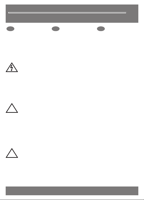
!Personen mit Herzleiden oder Herzschrittmacher dürfen nicht mit den aktivierten Sensoren in Kontakt kommen. Bei Arbeiten im Motorenraum Anlage vom Stromnetz trennen!Achtung Hochspannung - Danger haute Tension - Danger High Voltage
MARDERSCHUTZ
SENSOR
737
EinleitungIntroduction IntroductionDDEBitte lesen Sie vor dem Einbau die Bedienungs-anleitung genau durch. Um die Funktionstüchtigkeit von Fahr-zeug und Marderschutzgerät nicht zu beeinträchtigen, beachten Sie die Montageanleitung und die Sicherheitshinweise.DFRVeuillez lire attentive-ment ce mode d'emploi avant l'installation. Afin de ne pas nuire au bon fonctionnement du véhicule et de l'appareil anti-fouines, vous devez tenir compte des instructions de montage et des consignes de sécurité.DENPlease read the user manual carefully before installation. So as not to impair the functioning of the vehicle and the marten defence device, please refer to the installation instructions and safety instructions.Les personnes souffrant de troubles cardiaques ou portant un stimulateur cardiaque ne doivent pas entrer en contact avec les capteurs activés! Lors de travaux dans le compartiment moteur, débrancher l'installation du réseau électrique.People with heart conditions or pacemakers must not come into contact with the activated sensors. Disconnect from mains when working in the engine compartment! Der Marderschutz dient als Schutz vor Mardern im Motorenraum von Fahrzeugen. Unsach-mässiger Gebrauch und Verwendung ausserhalb des Verwendungsbereich schliesst jegliche Haftung und Gewährleistung aus.Verwendungszweck - Utilisation - PurposeThe marten defence guards against the entry of martens in the engine compartment of vehicles. If used incorrectly or outside the area of use, all liability and guarantees become void.Wird die Fahrzeugbatterie mit einem Batterielade- / Erhaltungsgerät über 13V aufgeladen, schaltet sich das Marderschutzgerät komplett aus.Batterieladegerät - Chargeur de batterie - Battery charger Si la batterie est rechargée à plus de 13V au moyen d'un chargeur de batterie/d'un chargeur de maintien, l'appareil de protection anti-fouines se déclenchera.If the vehicle's battery is charged with a battery or trickle charger above 13V, the marten defence device switches off completely.!La protection anti-fouines sert de protection contre les fouines dans le compartiment moteur du véhicule. Tout usage et/ou utilisation inappropriée hors du domaine d'application exclut toute responsabilité et garantie.4

Elektronikmodul:Module électroniqueElectronic module
StromkontaktplattePlaque de contact Electrical contact plate IsolatorIsolateurIsolator6x6xMontagebügelSupport de montage Mounting bracketKabelbaumFaisceau de câblesCable loomSicherungshalterPorte-fusibleFuse holderKFZ-SicherungFusible autoAutomotive fuseWarnkleberAutocollant d'avertissement Warning stickerStossverbinderProlongateur Butt connectorAUF GERÄT UND SENSORENACHTUNG HOCHSPANNUNGDanger ! Haute TensionDanger ! High VoltageBEI ARBEITEN IM MOTORENRAUM STECKER VOM GERÄT TRENNEN !ROT: GRÜN: ROT+GRÜN: HOCHSPANNUNG AUF SENSORENMARDERSCHUTZ BETRIEBSBEREITFEHLER - SIEHE BEDIENUNGSANLEITUNG
i
MARDERSCHUTZ
SENSOR
737
5
MARDERSCHUTZ
SENSOR
737
VerpackungsinhaltContenu de l'emballageUnit content 1 x Ringzunge - Langue annulaire - Ring tonque M51 x Isolierschlauch - Gaine isolante - Insulation tube 1.30m2 x Linsenblechschraube - Vis pour tôle à tête bombée - tapping screw 4.86 x Kabelbinder - Attache-câbles - Cable ties 300 x 4.66 x Kabelbinder - A 150 x 2.6ttache-câbles - Cable ties

AUF GERÄT UND SENSORENACHTUNG HOCHSPANNUNGDanger ! Haute TensionDanger ! High VoltageBEI ARBEITEN IM MOTORENRAUM STECKER VOM GERÄT TRENNEN !ROT: GRÜN: ROT+GRÜN: HOCHSPANNUNG AUF SENSORENMARDERSCHUTZ BETRIEBSBEREITFEHLER - SIEHE BEDIENUNGSANLEITUNG
i
MARDERSCHUTZ
SENSOR
737
6x
i
MARDERSCHUTZ
SENSOR
737
Allgemeine HinweiseIndications généralesGeneral informationDDEPraktische Erfahrungen zeigen, dass bei richtiger Montage der Sensoren ein Auf-enthalt für Marder im Motoren-raum kaum möglich ist. Vor dem Verbeissen von Fahrzeugteilen kriecht der Marder ausgiebig durch den gesamten Motoren-raum. Verteilen Sie deshalb die Sensoren im oberen zweiten Drittel des Motorenraumes überall dort, wo sich das Tier niederlassen will und gezwungenermassen mit den Sensoren in Kontakt kommen muss.DFRL es e x pé r ie n ce s pratiques montrent qu’ une fouine ne peut pas rester dans le compartiment moteur si les capteurs ont été installés correctement. Avant de s'acharner sur les pièces du véhicule, la fouine rampe longuement dans tout le compartiment moteur. Pour cette raison, vous devez répartir les capteurs dans les deux tiers supérieurs du compartiment moteur, partout où l'animal voudrait s'installer et auquel il doit nécessairement s'exposer au contact des capteurs.DENIf the sensors are correct-ly installed, it is practically impossible for the marten to stay in the engine compartment. Before chewing on the vehicle parts, it creeps throughout the engine compartment. The sensors should be positioned in the upper third of the engine compartment where it settles down, forcing it to come into contact with the sensors.Die Hochspannung wird bei Stop+Go Funktion zwei Minuten nach Motorabschaltung aktiviert. Nach Schliessen der Motorhaube wird die Hochspannung nach zwei Minuten aktiviert.La fonction Stop+Go active la haute tension 2 minutes après l'arrêt du moteur. La haute tension est activée 2 minutes après la fermeture du capot.The Stop+Go function activates the high voltage two minutes after the engine is switched off. The high voltage is activated two minutes after the bonnet is closed.6
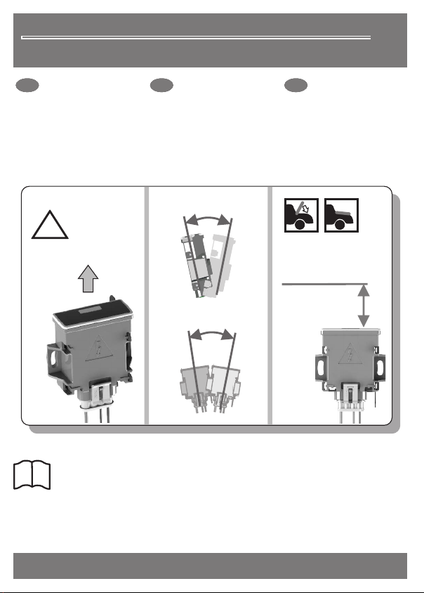
!ObenhautThis side up± 5°± 5°max. 15cmMotorhaubeCapotBonnet
i
7
MARDERSCHUTZ
SENSOR
737
Einbaulage ElektronikmodulPosition de montage module électronique Electronic module installation point DDEPlatzieren Sie das Elektronikmodul an einer wasser- und hitzegeschützten Stelle in senkrechter Lage im Motorenraum. Achten Sie darauf, dass sich keine Gegenstände zwischen dem Elektronikmodul und der Motorhaube befinden.DFRPlacez le module électronique dans le compartiment moteur, en position verticale et à un endroit protégé de la chaleur. Veillez à ce qu'il n'y ait aucun objet entre le module électronique et le capot.DENThe electronics module must be vertical and away from sources of water and heat. Make sure there are no objects between the electronic module and the bonnet.Das Sichtfenster des Elektronikmodul muss in Richtung der Motorhaube ausgerichtet sein. Der Abstand des Sichtfensters zur geschlossenen Motorhaube soll zwischen 2 und 15cm betragen.La fenêtre du module électronique doit être orientée vers le capot. L'espace entre la fenêtre et le capot fermé doit être comprise entre 2 et 15 cm.The window on the electronics module must face the bonnet. The distance from the window to the closed bonnet must be 2 - 15 cm.

MARDERSCHUTZ
SENSOR
737
Montage ElektronikmodulMontage du module électronique Assembly of electronic module DDEDas Elektronikmodul kann universell montiert werden. Der Montagebügel kann in sechs Varianten, gebogen oder flach verbaut werden. Das Modul kann auch ohne Montagebügel mittels Schrauben (im Liefer-umfang) montiert werden.DFRLe module électronique peut être monté dans n'importe quelle position. Le support de montage peut être monté en six versions, plié ou à plat. Le module peut également être monté sans support de montage à l’aide des vis comprises à la livraison.DENThe electronics module can be mounted in differ-ent positions. The mounting bracket can be fitted in six ways - bent or flat. The module can be mounted also with screws (included)..Mehrfaches Biegen kann zum Bruch des Montagebügels führen!Un pliage répété peut conduire à la rupture du support de montage !If the mounting bracket is bent too many times, it may break!!Montagebügel - Support de montage - Mounting bracket
Varianten - Variantes - Variantsverschraubtvisséscrewed in 8

9
MARDERSCHUTZ
SENSOR
737
Montage mit MontagebügelMontage avec support de montage Assembly with mounting bracket DDEBefestigen Sie den Montagebügel fest im Motorenraum. Schützen Sie die Bohrlöcher gegen Korrosion. Schieben Sie das Elektronikmodul gemäss Skizze auf die Laschen des Montagebügels bis dieses beidseitig einrastet.DFRFixez solidement le sup-port de montage dans le compartiment moteur. Protégez les perçages contre la corrosion. Introduisez le module électro-nique selon le schéma sur les languettes du support de montage, jusqu'à ce que celui-ci s'encliquette des deux côtés selon le schéma.DENSecure the mounting bracket firmly in the engine compartment. Protect the drill holes from corrosion. Slide the electronics module into the tabs of the mounting bracket (see diagram) until it snaps into place on both sides.Der Montagebügel ist für das einmalige Einrasten im Gehäuse ausgelegt!Le support de montage est conçu pour un encliquetage unique dans le boîtier !The mounting bracket is designed to be snapped into the housing once!!
«klick»«clic»«click»!Richtung beachten!Respecter l'orientation !Note the direction!2 x

10
MARDERSCHUTZ
SENSOR
737
Positionierung der SensorenPositionnement des capteurs Positioning the sensorsDDEGelbes Hochspannungs-kabel durch die Isola-toren ziehen. Probeweise Vor-verlegung des Hochspannungs-kabel und der Sensoren im ge-fährderten Bereich. Die Sensoren nicht im Bereich von Spritzwasser und in ausreichend grossen Ab-stand zu Hitzestellen montieren!DFRPasser le câble haute tension jaune à travers les isolateurs. Poser provisoi-rement le câble haute tension et les capteurs dans la zone menacée. Ne pas monter les capteurs dans la zone d'aspersion d'eau et les installer à une distance suffisante des sources de chaleur !DENPull the yellow high voltage cables through the isolators. Lay the cables and sensors in the affected area on a trial basis. Mount the sensors away from sprays and heat!Für Fahrzeuge mit Mittelmotoren können als Option zusätzliche Sensor-Sets bestellt werden
gelbes Kabelcâble jaune yellow cablePour les véhicules à moteur central, des jeux de capteurs supplémentaires peuvent être commandés en optionAdditional sensor sets can be ordered for vehicles with mid-mounted engines.
i

11
MARDERSCHUTZ
SENSOR
737
Montage der StromkontaktplattenMontage des plaques de contact Assembly of electrical contact plates DDESchieben Sie die Strom-kontaktplatten gemäss Abbildung gleichmässig auf den Isolator bis dieser an allen vier Rastnasen einrastet. Dadurch wird das gelbe Hochspannungs-kabel an zwei Stellen ange-stochen und kontaktiert.DFRGlissez les plaques de contact sur l'isolateur jusqu'à ce que celui-ci s'encliqu-ette sur les 4 nez d'encliquetage. De ce fait, le câble haute tension jaune est perforé et connecté à deux endroits. DENSlide the electrical contact plates onto the isolator as shown in the diagram until all four tabs are locked in place, thereby piercing through the yellow high-voltage cable in 2 places and creating the contact.Isolator und Stromkontaktplatte sind zum einmaligen Einrasten ausgelegt. Stellen Sie sicher, dass alle vier Rastnasen vollständig verrastet sind!!L'isolateur et la plaque de contact ont été conçus pour un encliquetage unique. Assurez-vous que les 4 nez d'encliquetage soient complètement engagés.The isolator and electrical contact plate are designed to snap in place once. Make sure that all four tabs are fully locked in!
«klick»«clic»«click»4 x

12
MARDERSCHUTZ
SENSOR
737
Montage der kompletten SensorenMontage des capteurs complets Assembly of complete sensorsDDERutschfeste Befestigung der Sensoren und Hoch-spannungskabel am definitiven Ort mittels Kabelbindern (Liefer-umfang). Beim letzten Sensor überschüssiges Hochspannungs-kabel bündig mit dem Isolator kürzen.DFRFixation antidérapante des capteurs et du câble haute tension à l'endroit définitif à l'aide des attache-câbles. Au niveau du dernier capteur, raccourcir le câble haute tension excédentaire à fleur avec l'isolateur.DENNon-slip mounting of the sensors and high-voltage cable in their definitive position using cable ties (included). On the last sensor, cut the excess high-voltage cable flush to the isolator.Die Stromkontaktplatten der Sensoren dürfen mit keinen masseführenden Karosserie-, Motorenteilen oder Gummischläuchen in Berührung kommen (Sicherheitsabstand zu Masse-teilen: 10mm), ansonsten wird die Spannung abgeleitet. Kurzschluss!!!Letzter SensorDernier capteurLast sensor10mmLes plaques de contact des capteurs ne doivent pas être en contact avec des éléments de carrosserie, ni du moteur reliés à la masse ou avec des tuyaux en caoutchouc (distance de sécurité par rapport aux pièces à la masse : 10mm). Dans le cas contraire, la tension sera dérivée et cela se traduira par un court-circuit.The electrical contact plates of the sensors must not come into contact with any mass conducting parts of the bodywork, engine or rubber hoses (safe distance to earthing parts: 10mm), otherwise voltage is deflected. Short circuit!
!

13
MARDERSCHUTZ
SENSOR
737
Anschluss KabelbaumBranchement du faisceau de câbles Connecting the cable loom
DDESchliessen Sie das braune Kabel an Masse an. Das rote Kabel mit dem Sicherungshalter verbinden. Dieser wird an die Stromversor-gung angeschlossen. Schützen Sie beide Kabel mit dem Isolier-schlauch. Sicherung noch nicht montieren!DFRConnecter le fil marron à la masse. Relier le fil rouge avec le porte-fusible au bloc d'alimentation. Protéger les deux fils avec de la gaine isolante. Ne monter pas encore le fusible !DENConnect the brown wire to the mass. Connect the red wire with the fuse holder. This is connected to the power supply. Protect both wires with the insulating tube. Do not install the fuse yet!Montieren Sie den Sicherungshalter möglichst nah an der Stromversorgung. Legen Sie die Sicherung noch nicht ein!!Monter le porte-fusible aussi près que possible de l'alimentation. Ne monter pas encore le fusible à ce stade!Mount the fuse holder as close to the power supply as possible. Do not insert the fuse yet!BraunMarronBrown!+30 (+)SicherungFusibleFuseRotRougeRedGelbJauneYellow 12V/ 24V= Hochspannung= Haute tension= High voltage= Stromversorgung (+)= Alimentation (+)= Power supply (+)= Masse (-)= Masse (-)= Mass (-)

2 Min.
SCHRITT 1 - ÉTAPE 1 - STEP 1
i
14
MARDERSCHUTZ
SENSOR
737
Kalibration - Schritt 1Calibrage - Étape 1Calibration - Step 1 DDEDie Kalibration muss bei der ersten Installation des Marderschutzgerätes durch-geführt werden um die korrekte Position der Motorhaube zu detektieren. Die Kalibration bleibt auch bei der Trennung vom Netz erhalten.DFRLors de la première installation de l'appareil de protection anti-fouines, il faut procéder au calibrage pour repérer la position correcte du capot. Le calibrage est mémorisé en cas de séparation du réseau.DENThe marten defence device must be calibrated when it is first installed so as to detect the correct position of the bonnet. The calibration is maintained even when discon-nected from the mains. Wird ein Motorhaubenschalter (optionales Zubehör) verwendet, ist die Funktion der Kalibration deaktiviert.Si un interrupteur de capot (accessoire en option) est utilisé, la fonction de calibrage sera désactivée. If a bonnet switch (optional accessory) is used, the calibration function is disabled.Die Kalibration kann nach Montieren der KFZ-Sicherung während zwei Minuten durchgeführt werden. Die Kalibration kann jederzeit durch ein erneutes Demontieren/ Montieren der KFZ-Sicherung wiederholt und neu ausgeführt werden.Le calibrage peut également être effectué dans les deux minutes suivant l'insertion du fusible automobile. Le calibrage peut être répété à tout moment pendant 120 secondes en démontant/remontant de nouveau le fusible auto.It can be calibrated for two minutes after the automotive fuse has been installed. The process can be repeated when the automotive fuse has been dismantled or installed.«klick»«clic»«click»

Achtung Hochspannung - Danger haute Tension - Danger High Voltage
SCHRITT 2 - 2 - STEP 2ÉTAPE
KFZ-Sicherung (3A) montierenInsérer le fusible automobile (3A)Install the automotive fuse (3A) Schritt 3Étape 3Step 35 Sek.5 Sec.15
MARDERSCHUTZ
SENSOR
737
Kalibration - Schritt 2Calibrage Étape Calibration - Step 2- 2In den ersten 5 Sek. nach dem Einlegen der Sicherung leuchtet die rote LED und signalisiert die Selbstprüfung. Während dieser Prüfzeit liegt an den SENSOR-Platten Hochspannung an.Durant les 5 premières secondes suivant l'insertion du fusible, la LED rouge s'allume et signale ainsi le test autonome. Pendant cette période de test, les plaques du SENSOR sont sous haute tension.In the first 5 sec. after inserting the fuse, the red self-test LED lights up. The SENSOR plates are under high voltage whilst the check is running.redgreenredslow(green )oderouor( )

16
MARDERSCHUTZ
SENSOR
737
Kalibration - Schritt 3Calibrage Calibration - Step 3- Étape 3
~ 12x10-20cm
SCHRITT 3 - ÉTAPE 3 - STEP 3
1 x Beeeeepgreengreen5 Sek.1 x Beeeeepgreen5 x BeepSchritt 4Étape 4Step 4Schritt 2Étape 2Step 2wartenattendrewaitWischbewegung über dem FensterMouvement balayant devant la fenêtre Wave your hand in front of the window gute Lichtverhältnissebonnes conditions de lumière good lighting conditions

SCHRITT 4 - ÉTAPE 4 - STEP 4
1 x Beeeeepgreen5 x Beep!Fenster komplett abdecken!Recouvrir complètement les fenêtres Cover the window completely!Schritt 55Step 5Étape Schritt 2Étape 2Step 217
MARDERSCHUTZ
SENSOR
737
Kalibration - Schritt 4Calibrage - Étape 4Calibration - Step 4
i
Das Fenster kann auch mit weissem Tuch abgedeckt werden.La fenêtre peut aussi être recouverte d'un tissu blanc.The window can also be covered with a white cloth.

SCHRITT 5 - - STEP 5ÉTAPE 5
18
MARDERSCHUTZ
SENSOR
737
Kalibration - Schritt 5Calibrage - Étape 5Calibration - Step 5
i
Bei Fehler: Überprüfen Sie die Einbaulage, Seite 7 (Abstand zur Motorhaube verringern!)En cas d'erreur : contrôler la position de montage, page 7If an error occurs, check the installation point, page 7.
1 x Beeeeepgreen5 x BeepMotorhaube schliessen!Fermer le capot! Close the bonnet!Schritt 66Step 6Étape Schritt 2Étape 2Step 2
SCHRITT 6 - 6 - STEP 6ÉTAPE
19
MARDERSCHUTZ
SENSOR
737
Kalibration - Schritt 6Calibrage - Étape 6Calibration - Step 6
1 x Beeeeepgreen5 x BeepMotorhaube öffnen!Ouvrir le capot! Open the bonnet!Schritt 2Étape 2Step 2greenOKDie Anlage ist betriebsbereitL'appareil est opérationnelThe system is readyÜberprüfen Sie die Einbaulage (Seite 7)Contrôlez la position de montage (page 7) Check the installation point (page 7)

Nach erfolgreicher Aktivierung des Funktionstests sind die Sensorplatten für zwei Minuten unter Hochspannung!Achtung Hochspannung - Danger haute Tension - Danger High Voltage20
MARDERSCHUTZ
SENSOR
737
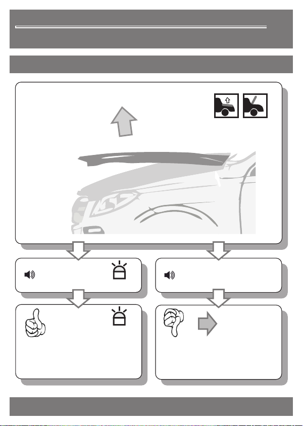
Überprüfung der FunktionenContrôle des fonctions Checking the functionsDDEDer Funktionstest (Aktivierung, siehe Seite 21) dient zum Kontrollieren der Spannung auf den Stromkontakt-platten. Dieser bleibt bei Akti-vierung zwei Minuten aktiv. Dabei wird das Sicherheitssystem zur Abschaltung der Hochspannung ausser Kraft gesetzt. Während dieser Zeit sind die Sensoren unter Hochspannung!DFRLe test de fonctionne-ment (activation, voir page 21) sert à contrôler la tension sur les plaques de contact. Celui-ci reste actif pendant 2 minutes après activation. Ce faisant, le système de sécurité qui coupe la haute tension est mis hors circuit. Durant ce temps, les capteurs sont sous haute tension !DENThe function test (activation, see page 21) is used to check the voltage to the electrical contact plates. This remains active for two minutes when activated. The safety system for switching off the high voltage is overridden during that time and the sensors are under high voltage!Après l'activation réussie du test de fonctionnement (page suivante), les plaques de capteur sont sous haute tension durant 2 minutes !After successfully activating the function tests, the sensor plates are under high voltage for 2 minutes!Nach Aktivierung des Funktionstests (nachfolgende Seite) sind die Sensorplatten während zwei Minuten unter Hochspannung. Nach Ablauf dieser Zeit wird die Hochspannung bei offener Haube automatisch abgeschaltet und die Anlage ist wieder betriebsbereit.Après l'activation du test de fonctionnement (page suivante), les plaques de capteur sont sous haute tension durant 2 minutes. Dès que ce temps est écoulé, la haute tension est automatiquement mise hors circuit à l'ouverture du capot et l'appareil est de nouveau opérationnel.After activating the function test (following page), the sensor plates are under high voltage for 2 minutes, after which the high voltage switches off automatically when the bonnet is opened. The system is now ready for use again.2 Min.Jedes Schliessen der Motorhaube wird mittels akustischem Signal bestätigt (1x Beeeeep/ LED blinkt grün). Zwei Minuten nach Schliessen der Motorhaube schaltet die Anlage auf Hochspannung (1x Beeeeep/ LED blinkt rot)Chaque fermeture du capot est confirmée par un signal acoustique (1x Beeeeep/ LED clignote en vert). Deux minutes après la fermeture du capot, l'appareil commute sur la haute tension (1x Beeeeep/ LED clignote en rouge).You will hear a signal every time the bonnet is closed (1x Beeeeep / green LED flashes). Two minutes after the bonnet has been closed, the system switches to high voltage (1x Beeeeep / red LED flashes).
Table of contents


